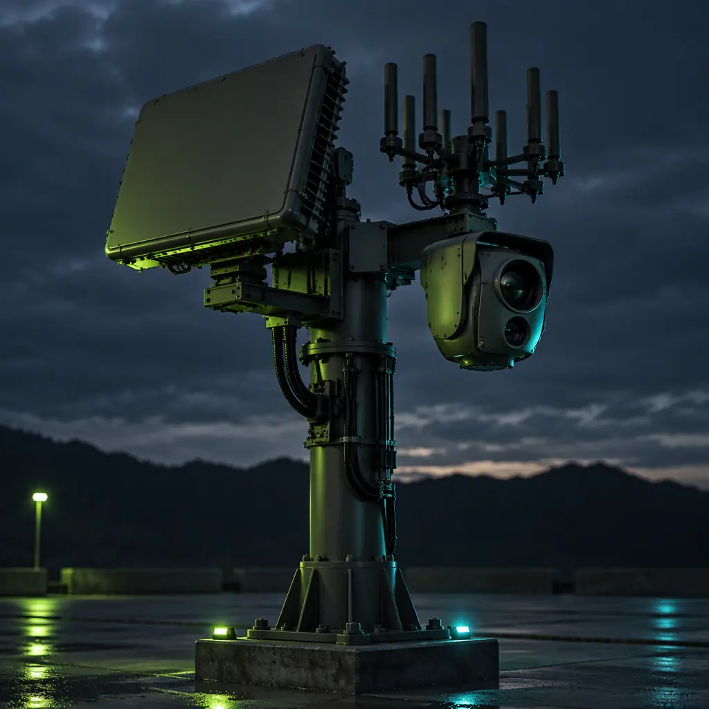
The first thing a procurement team learns about counter-UAS detection is that a stated detection range is almost meaningless without the target that range was measured against. A radar advertised at 5 kilometres may achieve that against a 1 m² reference sphere and lose more than half of it against the aircraft you actually care about. A group 1 quadcopter with a plastic and carbon airframe, a small battery and a thin wire antenna presents a radar cross-section in the region of 0.01 m², and radar range scales with the fourth root of cross-section, so the arithmetic is unforgiving. Halving the cross-section does not halve the range, it reduces it by a factor of about 0.84, but dropping from 1 m² to 0.01 m² cuts the range to roughly 32 percent of the reference figure. A 5-kilometre radar becomes a 1.6-kilometre radar, and that number was computed in free space, clear of clutter and before anyone asked what a treeline does to it.
This arithmetic is why a credible counter-UAS detection chain is almost always multi-modal. No single modality sees everything, and the modality that fails against one target class is precisely the one that succeeds against another. Specifying the chain means understanding which physics covers which gap. The defense and security components guide covers hardening the friendly aircraft's own links against jamming; this article is the inverse problem, the sensor stack that finds somebody else's aircraft in your airspace.
The four detection modalities and their honest coverage
Counter-UAS detection reduces to four physical principles. Each detects a different emission or reflection, and each therefore has a characteristic target class it is good at, a characteristic target class it misses, and a characteristic false-alarm mechanism that has to be designed around.
Radar transmits energy and detects the reflection. It is the only modality that gives range and velocity directly and independently of the target's cooperation, which makes it the backbone of most detection chains. Its weakness against small UAVs is the cross-section problem above, compounded by clutter: a low, slow target at short range is exactly what ground clutter rejection is designed to suppress, so a radar tuned to reject terrain and birds will also reject a hovering quadcopter unless it has a specific small-UAV mode. Look-down geometry near the horizon is the hardest case, and a radar mounted low will underperform its datasheet against exactly the targets that matter.
RF detection and direction finding exploits the fact that almost every commercial drone is emitting. The aircraft's control link and its video downlink are radio signals, and a receiver array can detect their presence and estimate the bearing of the emitter. This is the highest-value modality for the group 1 commercial threat, because it detects at ranges governed by the link budget rather than by the target's physical size, and because it can often classify the protocol and therefore the aircraft type. Its blind spot is definitional: a drone flying a pre-programmed waypoint mission with its transmitters off is radio-silent and therefore invisible to RF. It also cannot give range from a single direction-finding site, only bearing, so two or more sites are needed for a position fix.
EO/IR is the confirmation and identification layer. A wide-field camera or thermal imager detects motion against a background and a narrow-field imager classifies what was detected. EO/IR rarely contributes the initial detection at range, because the angular size of a 30-centimetre object at 1 kilometre is a fraction of a milliradian and smaller than a single detector element on a wide-field sensor. Its value is in the verification chain: RF or radar says something is there and roughly where, and the gimballed imager confirms that it is an aircraft and not a bird or a plastic bag. Thermal adds the ability to work at night and improves contrast against sky, though a small electric aircraft has little thermal signature of its own and is mostly detected as a silhouette against a warmer background.
Acoustic detection listens for the characteristic blade-pass and motor tones. It is inexpensive, entirely passive, and performs best in quiet environments where the ambient noise floor is low, which makes it useful for fixed sites at night and unreliable next to a road, a generator or wind. Its range is short, commonly a few hundred metres for a small quadcopter in a quiet setting and far less in noise, but it is unaffected by the cross-section and emission problems that limit the other modalities, and it can be the only sensor that works against a small radio-silent electric aircraft at close range.
| Modality | Gives range | Beats this target | Blind to this target | Dominant false-alarm source |
|---|---|---|---|---|
| Radar | Yes, direct | Larger airframes, any emission state, all weather | Small plastic airframes at low altitude in clutter | Birds, ground vehicles, terrain, wind-blown debris |
| RF detect / DF | No, bearing only from one site | Emitting commercial drones of any size | Radio-silent autonomous flight | Wi-Fi, consumer electronics, other legitimate emitters |
| EO/IR | Angle only | Confirmation, identification, night operation | Small angular targets at long range, cloud, glare | Birds, aircraft, insects near lens, heat shimmer |
| Acoustic | Rough, close range | Radio-silent electric aircraft, quiet sites | Noisy environments, windy conditions | Road traffic, machinery, weather, wildlife |
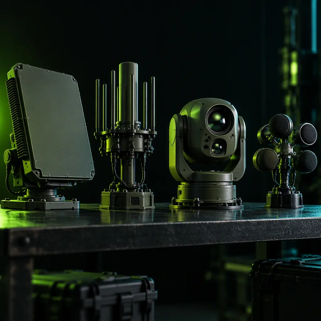 Four physics, four blind spots, one chain
Why radar range against a small UAV collapses, and what to do about it
The radar equation is the reason counter-UAS radar specifications are so often disappointing, and understanding it changes what you ask a supplier for. Received power from a target falls with the fourth power of range: half the range means one-sixteenth the received power. To buy back range you can raise transmitted power, raise antenna gain, lower the receiver's noise figure, or accept a worse detection threshold. Only the last is free, and it is not free at all, because it is paid for in false alarms. This is the central trade of counter-UAS radar design and the reason a specification that demands both maximum range and minimal false alarms against small targets is asking for two incompatible things.
Practical consequences for a procurement specification are specific. First, define the reference target. Insist that the stated detection range, detection probability and false-alarm rate are all quoted for a target cross-section, altitude band and trajectory that resemble your threat, not for a calibration sphere. A specification that says "detects group 1 UAVs at 3 km" is unverifiable; one that says "0.9 probability of detection of a 0.01 m² cross-section target at 2 km, 100 m altitude, radial approach, false-alarm rate below one per hour per square kilometre" is something a supplier can be held to.
Second, ask about clutter rejection specifically. The small-UAV problem is fundamentally a low-slow-small detection problem, and the techniques that address it, doppler filtering tuned to slow targets, micro-doppler analysis to distinguish a rotating propeller from a walking human or a swaying branch, and track-before-detect processing, are differentiating features rather than commodity ones. A radar without micro-doppler capability will produce bird tracks that a human operator has to sort out, and that operator workload is a real and often unbudgeted cost. The RF spectrum management guide covers the adjacent problem of coordinating the frequencies your radar occupies, which is a licensing question that can delay a deployment more than the hardware does.
Third, place the radar where its geometry works. A radar on the ground looking up at a target against clear sky performs very differently from the same radar looking down into clutter. Elevating the antenna, siting it so the horizon is a clean boundary, and giving the target a sky background changes real detection range more than a modest increase in transmit power. This is a site-engineering decision that has to be made before the radar is bought, and the site survey is not optional.
RF direction finding: the modality that detects by link budget rather than by size
RF detection inverts the radar problem. Instead of trying to see a small physical object, it listens for a signal whose strength depends on the transmitter power, the antenna gain at each end, the path loss and the receiver sensitivity. The path loss also grows with range, but there is no fourth-power cross-section term, so against an emitting commercial drone the achievable detection range is often substantially greater than radar's, and it does not degrade as the airframe shrinks. This is why RF is usually the first modality specified for a civil counter-UAS installation and radar the second.
What a direction-finding system actually measures is the bearing of the emitter, and the accuracy of that bearing depends on the antenna array's aperture and the processing method. A multi-channel array using phase comparison or amplitude comparison across separated elements can achieve bearing accuracies in the low single-digit degrees, which translates to a cross-range error at 2 kilometres on the order of 35 to 100 metres, a wide enough band that bearing alone rarely localises an emitter usefully. A single DF site gives you a line of bearing, not a position. Two or more sites with a common time reference allow triangulation and produce an actual position, and that requirement has to be designed into the deployment from the start: the sites need synchronisation good enough to correlate a detection across them, and the fusion layer needs to associate bearings from different sites with the same emitter, which is not trivial when several drones are airborne or when consumer Wi-Fi produces bearing noise.
Three specification points separate a capable RF detection system from a demonstrator. First, the frequency coverage and the signal library. Commercial drone control links and video downlinks occupy several bands, and the value of the system depends on how much of that space it covers and how many protocols it can recognise. A wideband receiver with a library that names the protocol converts a detection into an actionable identification, and the library has to be updatable, because drone link protocols change. Ask how updates are delivered and how often. Second, the sensitivity and the dynamic range: a receiver that is sensitive enough to hear a distant drone at low power density can be swamped by a nearby strong emitter, and a DF array that saturates near an airport or a broadcast tower produces bearing errors exactly when it is needed most. Third, the false-alarm behaviour against legitimate emitters. A city environment is full of emitters in the same bands, and a system that reports every Wi-Fi access point as a threat is unusable. The specification should state how legitimate emitters are excluded, whether by protocol recognition, bandwidth signature, power-progression logic or operator-managed allowlists.
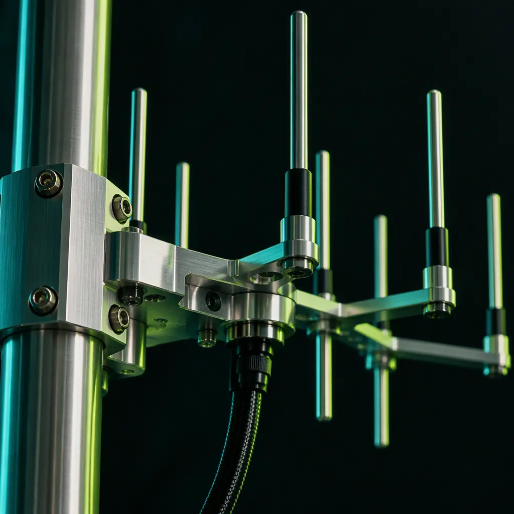 One site gives a bearing; two give a position
The fusion layer: where detections become decisions
A counter-UAS installation with four modalities and no fusion layer produces four independent alarm streams and an operator who cannot tell whether the radar track and the RF bearing are the same aircraft. The fusion layer is the component that converts sensor reports into a single track picture, and it is the part most often left out of a specification because it is software and therefore invisible in a bill of materials. Omitting it is the most common reason a well-equipped site performs poorly.
Fusion does three jobs. The first is association: deciding which reports from which sensors describe the same object. This is straightforward when timestamps and geometries are good and difficult when they are not, and the requirement it places on the hardware is that every sensor reports with a common time base and in a common coordinate frame. A one-second timing error at 20 metres per second of target motion is a 20-metre offset, which can be the difference between a confident association and two separate false tracks.
The second job is classification and confidence. A track should carry a declared identity and a confidence value, not just a position. That confidence is what allows an operator, or an automated response, to treat a high-confidence drone track differently from a marginal acoustic detection, and it is what allows a system to suppress the false alarms that each individual modality inevitably generates. The classification should be explicit about what evidence supports it: an RF protocol identification is strong evidence, a radar micro-doppler signature is strong evidence, a thermal silhouette is moderate evidence, and an acoustic tone is weak evidence in anything but a quiet environment. The system should present these differently rather than collapsing them into one undifferentiated alert.
The third job is track management under failure: what happens when a sensor drops out. Detection chains are specified for the case where everything works. Real installations lose a sensor to a fault, a power event or a network partition, and the system's behaviour in that condition is a design property. A chain that silently degrades to a single modality without telling the operator has converted a redundant system into an unreliable one without anyone noticing. The specification should require that sensor health be visible, that degraded operation be declared rather than hidden, and that the system continue producing a usable track picture with the modalities that remain. For installations where the detection chain feeds an automated response, the detect-and-avoid integration guide covers the adjacent cooperative-traffic problem and how DAA decision chains are structured, which is a useful reference for how a fusion layer should hand off to a decision layer.
Acceptance testing: distinguishing a detection chain from a demonstration
Counter-UAS detection is usually demonstrated under conditions that flatter it. A single cooperative target, flown on a predictable radial approach, on a clear day, with a technician watching the display and calling the detection verbally. A chain that passes that demonstration may still fail in service, because the conditions that make detection hard were all absent. The acceptance test is what closes that gap, and it should be written before the purchase order and included as a contractual condition.
A test that means something has five properties. It uses targets of the correct cross-section and material, not a convenient larger airframe, because that is the variable the whole radar range calculation turns on. It includes a radio-silent profile, an aircraft flying a pre-loaded waypoint mission with its transmitters off, because that is the case where RF detection contributes nothing and the radar, EO/IR and acoustic sensors have to carry the load alone. It includes a low-altitude, near-horizon approach, because that is the clutter case and the case where look-down geometry is worst. It is run long enough to measure false alarms, since a false-alarm rate is a statistical quantity and a one-hour trial cannot establish a figure that matters at a site operating continuously; a trial of at least several days in the actual installation environment is the only way to produce a number with meaning. And it is scored on a declared metric, probability of detection at a stated range band and altitude, time from first detection to track declaration, bearing or position accuracy, and false alarms per unit time, all recorded rather than judged.
The single most useful test is the one most often skipped: a multi-target trial. Two aircraft airborne simultaneously, one emitting and one silent, flown on crossing tracks, is the scenario that exposes association failures, and it is the scenario a real installation faces the first time there is a genuine incursion during a legitimate flight. A chain that has never been tested against two targets has not been tested.
The bottom line: specify counter-UAS detection as a chain rather than as a list of sensors, define the reference target cross-section for every range claim, place the radar where its geometry works and ask specifically about micro-doppler and clutter rejection, treat RF direction finding as a bearing source that needs a second site and a protocol library to be useful, budget the fusion layer as the component that makes the rest of the chain coherent, and hold acceptance to a multi-target trial with a radio-silent profile that runs long enough to produce a false-alarm figure. EMS Drone supplies UAV platform and payload hardware for security and public-safety operators, and works with detection-system integrators on the airframe, gimbal and interface components that a counter-UAS installation depends on. Send us the site geometry, the target classes you need to detect and the environment the system has to work in, and we will return a component and interface recommendation, the specification language for detection performance, and the acceptance-test structure that holds a supplier to a number.
Explore Capabilities Back to Blog
Continue Reading

Defense & Security Components
MIL-STD ruggedization, encrypted links and the trusted supply chain.
UTM & Detect-and-Avoid
Cooperative traffic, ADS-B and the DAA decision chain for BVLOS.
RF Spectrum Management
Frequency coordination, licensing and interference control.
Public Safety Components
Thermal payloads, encrypted links and rapid-deployment airframes.