
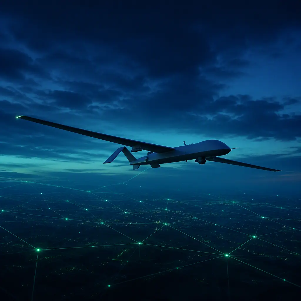
BVLOS is not a single approval and not a single component. It is a chain of capabilities — the aircraft must be visible to the airspace system (remote ID), aware of the traffic around it (detect-and-avoid), controllable beyond the radio horizon (C2 link resilience), and able to execute the contingency plan when anything degrades (autonomy and flight termination). The regulatory frameworks differ by region — the FAA's Part 89 remote ID rule and the BVLOS rulemaking under the FAA Reauthorization Act, EASA's U-space and Specific Operations Risk Assessment (SORA), the UK CAA's BVLOS path — but the component requirements converge. This article walks the chain from the airspace layer down to the bill of materials, so a procurement team can specify the aircraft electronics for a BVLOS program with the same rigor as the propulsion system.
What BVLOS actually requires: the regulatory chain from remote ID to DAA
The regulatory logic of BVLOS runs in three layers. First, the aircraft must identify itself — remote ID makes every UAS visible to regulators, other airspace users and UTM service providers, which is the precondition for operating where a human observer cannot keep visual contact. Second, the aircraft must be able to avoid collisions it cannot see from the ground — detect-and-avoid replaces the remote pilot's eyes with sensors and onboard decision logic. Third, the operation must fit into the traffic management system — the flight plan, the geofences, the contingencies and the telemetry are exchanged with UTM services, not just with the pilot's ground station.
In the United States, the FAA's Part 89 rule (Standard Remote ID, in force since March 2024) requires broadcast and network remote ID for the aircraft classes that apply to commercial operations. The BVLOS rulemaking mandated by the FAA Reauthorization Act of 2024 is the framework that will replace the current case-by-case waiver path (107.31 waivers and Part 135 operations specifications) with a performance-based standard — and every draft of that standard leans on the same building blocks: remote ID, DAA, C2 link robustness and contingency procedures. In Europe, EASA's U-space regulation (the EU 2021/664 framework) requires e-identification, geofencing and traffic information services in U-space airspace, and the SORA process grades the operation's risk and the mitigation the aircraft must carry. The UAV certification and compliance guide covers the certification documentation chain that ties these airspace rules to the component evidence, and the UAV remote ID and BVLOS compliance guide covers the remote ID regulatory detail in depth — this article focuses on the component integration decisions.
The procurement consequence: the aircraft electronics for a BVLOS program are specified by regulation, not by preference. The flight controller, the navigation stack, the radios and the compute module must all support the remote ID and DAA functions — which is a different specification process than buying a VLOS inspection platform and is worth doing before the airframe is selected, not after.
 Concept illustration
Remote ID components: broadcast and network modules
Remote ID is the identity and position broadcast that makes the aircraft visible to the airspace system. The component decision has three options: a broadcast-only module (Wi-Fi Beacon and/or Bluetooth), a network-only module (cellular), or a broadcast-plus-network module. The ASTM F3411 standard (the F3411-22a revision is the current baseline) defines the message set, the transmission requirements and the performance — the procurement specification should cite the standard revision explicitly, because the earlier revisions are not interchangeable.
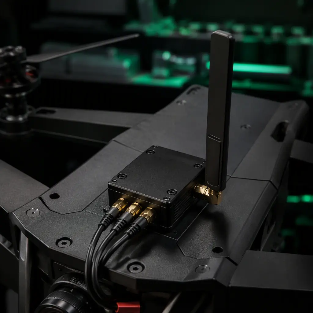
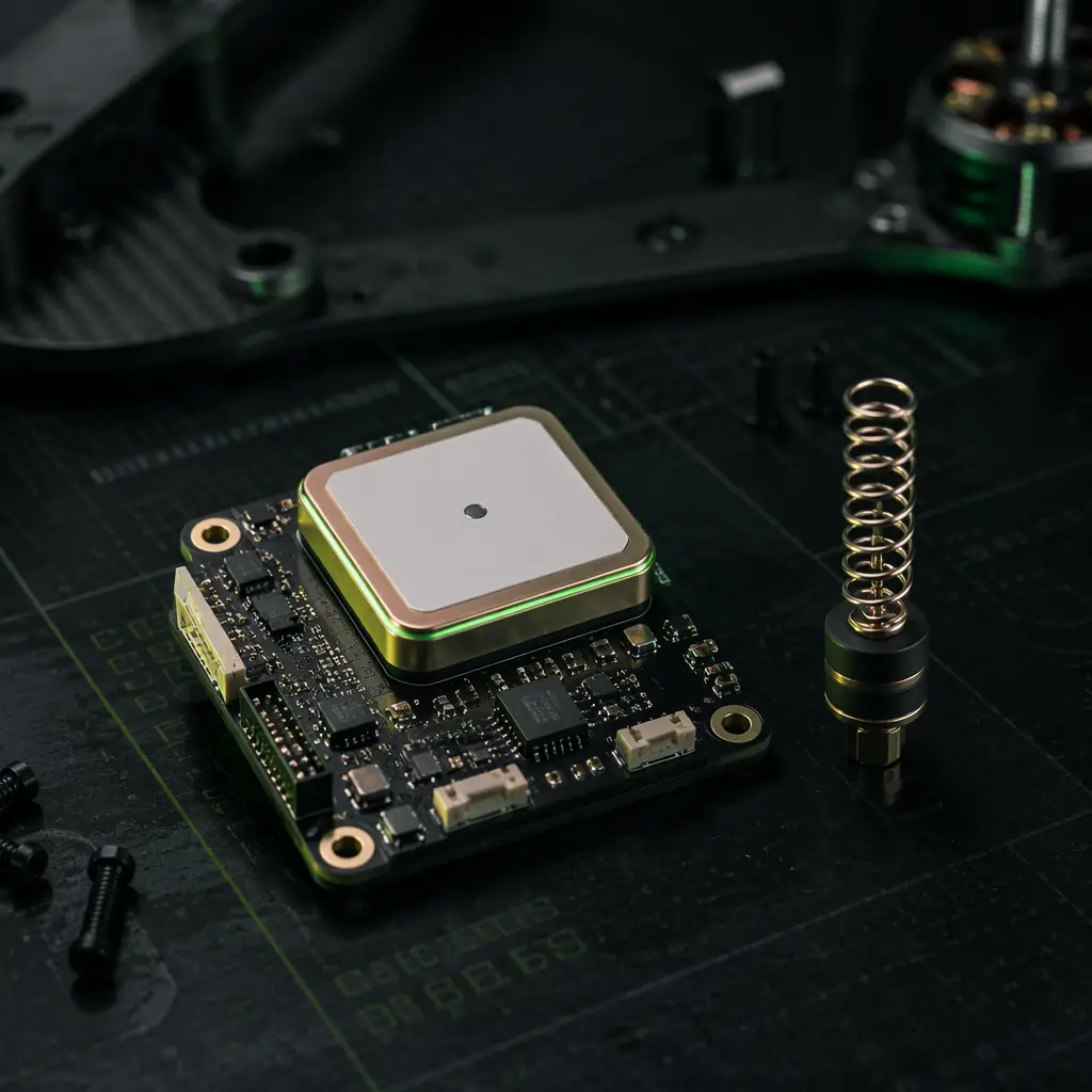
The broadcast module. The module transmits the ASTM F3411 message set over Wi-Fi Beacon (802.11 in beacon mode) or Bluetooth 4.0 — the aircraft ID, the operator ID or location, the aircraft position, altitude, velocity, the control station position, a time mark and the emergency status, at a 1 Hz update rate. The practical range of the Wi-Fi Beacon broadcast is roughly 1–3 km to a compatible receiver, which covers the near-airspace visibility requirement; the module must be integrated with the aircraft's position source (the GNSS receiver) and its power bus, and the antenna placement matters — the broadcast is omnidirectional and the airframe structure (carbon fiber in particular) can shadow it, so the module antenna should be positioned to avoid the propellers, the payload and the carbon laminate. The GNSS module selection guide covers the position-source requirements that the remote ID message depends on — the remote ID position accuracy is only as good as the navigation source feeding it.
The network module. The network remote ID path delivers the same message set over a cellular (LTE/4G) connection to the UTM service providers, which makes the aircraft visible beyond the broadcast range — the visibility that matters for BVLOS operations along a pipeline or a power line where the aircraft is tens of kilometers from any observer. The network module adds a SIM/eSIM, a cellular modem and the integration with the operator's USS account; the coverage question (the cellular coverage along the mission corridor) becomes an operational constraint that belongs in the flight-planning process, not just the component spec.
Integration requirements. The remote ID module must receive the aircraft position and status from the flight controller (typically over UART or CAN), must fail in a defined way if the position source degrades (the ASTM standard defines the behavior when GNSS is lost — the message set includes a position source flag), and must not interfere with the control and telemetry links. The spectrum question matters: the Wi-Fi Beacon transmission shares the 2.4 GHz band with the control link in many platforms, and the coexistence plan (channel selection, transmission timing) should be part of the integration spec. The UAV RF communication systems guide covers the frequency planning and the coexistence analysis for the full radio stack.
Detect-and-avoid sensors: ADS-B, radar, vision and the fusion requirement
Detect-and-avoid replaces the pilot's eyes. The sensor suite must detect cooperative traffic (aircraft carrying transponders or ADS-B Out), non-cooperative traffic (aircraft, drones and obstacles without any electronic signature), and provide the tracking data that the avoidance logic needs. No single sensor class covers all three, which is why the DAA system is a sensor fusion problem — and why the procurement spec must treat the fusion compute as a first-class component, not an afterthought.
ADS-B In. The ADS-B receiver (1090 MHz extended squitter) detects cooperative traffic — the airliners, general aviation and increasingly the drones that transmit ADS-B or equivalent surveillance data. The 1090ES receiver is a mature, low-power module (a few watts, a small blade or patch antenna) with a detection range of tens of nautical miles for high-power transponder traffic. The two limitations: ADS-B only sees aircraft that broadcast (a non-transponder drone or a glider is invisible), and the 1090 MHz band is congested — the receiver's filtering and its ability to reject interference define the usable tracking performance. For a BVLOS corridor that crosses general aviation traffic, ADS-B In is the baseline cooperative sensor; for operations in congested low-altitude airspace, it is necessary but not sufficient.
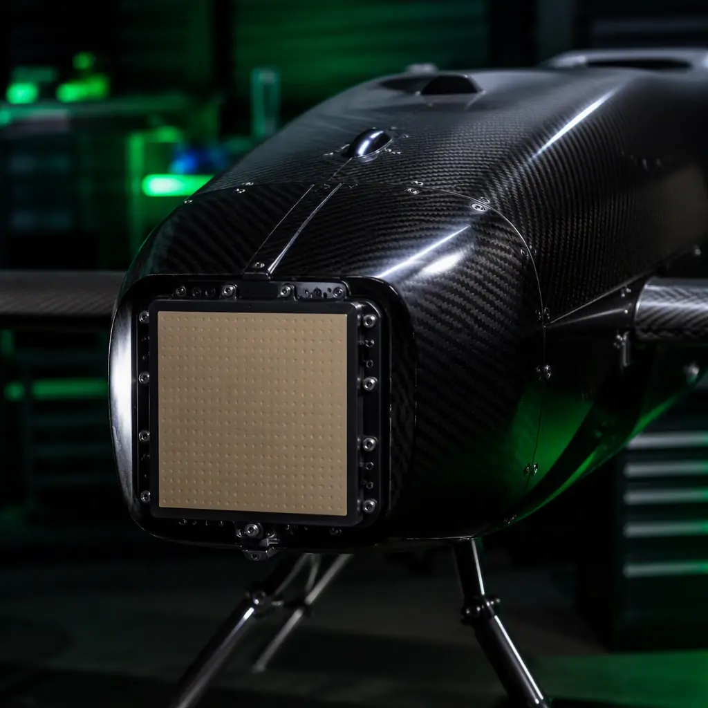
Radar. Compact radar — typically the 77/79 GHz automotive-grade FMCW modules adapted for airborne use, or the purpose-built UAS detection radars — detects non-cooperative traffic by reflection, with no cooperation required. The performance envelope: small-UAS detection at 100–400 m depending on the target radar cross-section and the mounting, range and velocity directly measured, and a wide field of regard when multiple modules are used. The trade-offs are weight (0.5–2 kg for the airborne-qualified units), power (tens of watts), and the mounting and vibration requirements — the radar needs a stable platform and a clear field of view, which interacts with the airframe design. For the defense and security operators, the UAV defense and security components guide covers the hardened and anti-jam variants of the detection and link hardware.
EO/IR vision. Camera-based detection runs a neural network detector on the video stream to find aircraft and drones by appearance — the sensor that "sees" what radar and ADS-B cannot resolve at close range and that verifies the target before the maneuver. The detection range is set by the optics and the sensor resolution: a 20 mm lens with a 12 MP sensor detects a small multirotor at roughly 200–500 m in good light, with the range falling in haze and darkness (an IR camera extends the night capability). The compute requirement is the cost driver: running a real-time detector at 10–30 frames per second needs 10–50 TOPS of edge AI performance — the class of compute covered in the UAV edge AI and onboard computing guide. The vision DAA is also the sensor that integrates with the avoidance path planning, because it produces the target bearing and angular rate that the maneuver logic consumes.
The fusion requirement. The DAA sensor manager fuses the ADS-B tracks, the radar tracks and the vision tracks into a single air picture — track association (deciding that the radar blip and the vision target are the same aircraft), track quality, and the threat assessment per track. The fusion runs on the same edge compute module as the vision detector (a Jetson-class or Hailo-class device with 26–100 TOPS), and its output feeds the autopilot's avoidance logic. The sensor fusion and redundant navigation guide covers the navigation-side fusion; the DAA side is the same discipline applied to the outside world. The procurement spec should name the fusion architecture — which sensors feed which trackers, and what happens to the DAA function when each sensor degrades — because the redundancy story is what the regulator and the operator both audit.
 Concept illustration
The DAA decision chain: detection range, tracking latency and the avoidance maneuver
Detecting traffic is only the first link in the chain; the DAA system must decide and maneuver. The decision chain has four stages, and the component specification affects every stage:
Detection range vs closure rate. The required detection range is set by the closing speed and the maneuver performance of the platform. A fixed-wing BVLOS aircraft cruising at 25 m/s meeting a general aviation aircraft at 50 m/s has a 75 m/s closure rate: a 10-second decision-and-maneuver cycle needs roughly 750 m of detection range, which is inside the radar and vision envelope but requires the sensors to actually deliver that range in the operating conditions (haze, rain, sun angle). The requirement flows down to the lens, the sensor, the detector model and the radar configuration — the spec should state the worst-case detection range against a defined target (for example, "a 1 m² RCS target at 400 m in 2 km visibility").
Tracking latency. The end-to-end latency from photon to maneuver command — the sensor frame time, the detector inference, the tracker update, the threat assessment and the autopilot response — must fit inside the decision cycle. The budget is typically 100–500 ms for the detection-and-tracking portion; a 300 ms latency at a 75 m/s closure rate costs 22 m of separation, which is why the compute selection (the inference latency of the vision detector) and the communication path (the DAA output to the autopilot over a deterministic interface) are specified numbers, not marketing claims.
Threat assessment and well clear. The tracker maintains each target's predicted trajectory and computes the closest point of approach (CPA) and the time to CPA. The RTCA DO-365 minimum operational performance standards for UAS DAA systems define the "well clear" boundary — in the DO-365 MOPS, well clear is defined at 4,000 ft (approximately 1,220 m) horizontal and 450 ft (approximately 137 m) vertical separation for the cooperative case, with the alerting thresholds tuned per platform and per airspace class. The threat assessment logic (which targets trigger an alert, when, and at what confidence) is part of the DAA system design, and the aircraft's performance — its turn rate, its climb capability — determines whether the required avoidance maneuver is physically achievable, which links the DAA specification to the UAV safety and redundancy systems design.
The avoidance maneuver and the autopilot interface. The avoidance logic produces a maneuver — a heading change, an altitude change or a speed change — that is passed to the flight controller. The integration architecture matters: the DAA system can command the autopilot through the mission interface (the same interface that the ground control station uses, in ArduPilot and PX4 terms) or through a dedicated avoidance interface, and the handover between the DAA command and the operator's command must be deterministic — who wins when the operator commands one way and the DAA commands another is a defined policy, not a runtime decision. The ArduPilot vs PX4 comparison covers the autopilot capabilities and interfaces that the DAA integration consumes, and the communication protocols guide covers the CAN, MAVLink and serial interfaces between the DAA compute, the remote ID module and the flight controller.
 Concept illustration
C2 link resilience: dual-link, link budget and the degraded-mode handover
Command and control (C2) is the link that carries the control commands and the telemetry between the pilot and the aircraft. In VLOS operation a lost link means the pilot watches the aircraft fly away and recovers it visually; in BVLOS operation the lost-link behavior is the contingency plan, and the C2 architecture is specified to make the loss a defined, handled event rather than an emergency. The resilience architecture has three parts:
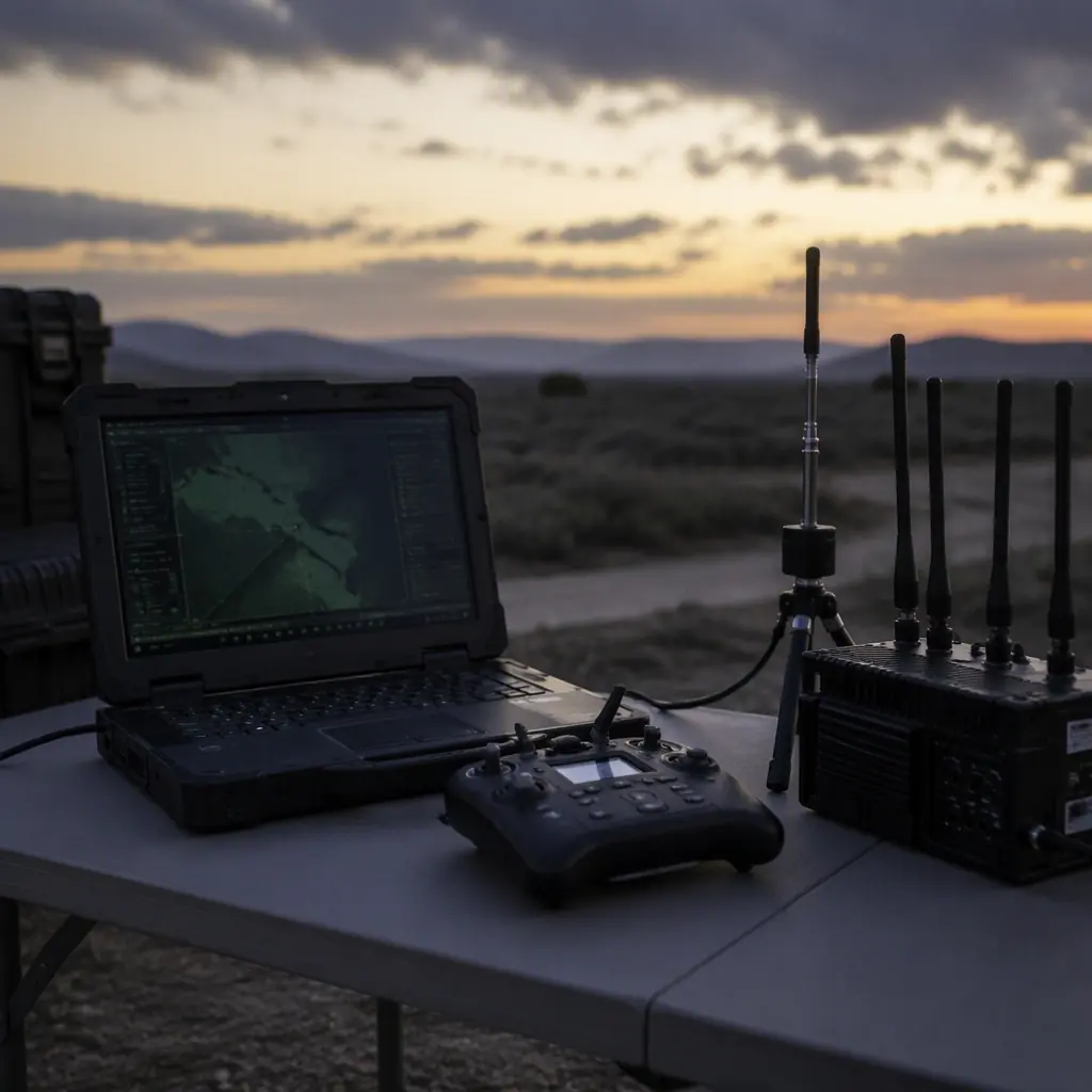
The dual-link design. The primary link is the high-bandwidth digital link — typically 2.4 GHz or 5.8 GHz for the video and the telemetry — and the secondary link is the independent path: a 4G/LTE cellular link, or the 868/915 MHz telemetry band that trades bandwidth for range and propagation. The two links must be physically and electrically independent — separate radios, separate antennas, and ideally separate power feeds — so that a single failure (a radio, an antenna, a cable) cannot take out both. The link architecture and the frequency planning are covered in the UAV RF communication systems guide; the resilience requirement here is that the handover between the links is automatic, tested and logged.
The link budget. The BVLOS C2 range is a link-budget calculation, not a datasheet claim: the transmit power and the antenna gain at each end, the free-space path loss over the mission range, the fade margin for the terrain and the weather, and the receiver sensitivity. The practical number for a mid-size multirotor with a 2.4 GHz digital link at 1 W EIRP is a control range in the tens of kilometers in line of sight, with the margin collapsing in rain and over terrain — which is why the BVLOS corridor planning includes a link analysis per route segment. The procurement spec should state the required range at a defined margin (for example, "20 km control range with 10 dB fade margin at 30 dBm EIRP") and require the measured link performance, not the chipset's marketing range.
The degraded-mode handover. The aircraft behavior when the primary link degrades is a designed sequence: the handover to the secondary link, the telemetry downsampling, the operator notification, and — if both links fail — the lost-link contingency (return to a defined point, hold position, or land at the planned alternate) executed by the flight controller from its onboard state. The lost-link behavior is one of the contingency procedures that the BVLOS approval reviews, and the UAV safety and redundancy systems guide covers the fail-safe design and the redundant avionics that make the contingency executable. The C2 resilience is also where the public safety and environmental monitoring mission profiles diverge — the first prioritizes link robustness in congested urban RF, the second prioritizes range in remote terrain, and the component selection follows the mission.
Airspace integration: UTM service providers, geofencing and contingency procedures
The aircraft-side components connect to the airspace system through the UTM services: the UAS Service Supplier (USS) that the operator uses to file the flight plan, exchange the telemetry and receive the traffic information; the Flight Information Management System (FIMS) layer that connects the USSs to the air navigation service provider; and, in Europe, the U-space services — e-identification, geofencing, flight authorization and traffic information. The ASTM F3548 standard defines the UTM technical framework, and the aircraft integration points are three:
The flight plan and telemetry exchange. The operation's flight plan (the 4D trajectory — position and time) is filed through the USS before the flight, and the aircraft's real-time position is exchanged during it. The aircraft-side requirement is the interface: the flight controller and the network remote ID module must provide the position and status stream that the operator's USS integration consumes — which is a MAVLink or custom telemetry integration on the ground station side, and the cellular network remote ID on the aircraft side. The ground control station hardware guide covers the operator-side compute and display that hosts the USS client.
Geofencing. The geofence is the operational boundary — the airspace volumes the flight may and may not enter, from the permanent restricted areas to the temporary flight restrictions (TFRs) and the U-space geofences. The enforcement can be ground-side (the USS or the ground station stops the mission) or aircraft-side (the onboard geofence database and the GNSS position trigger a response), and the aircraft-side enforcement is the layer that keeps the aircraft inside the approved volume when the link is lost. The geofence logic runs on the flight controller or the companion computer, uses the navigation position, and its response — turn back, land, hold — is part of the contingency set. The position integrity requirement connects to the GNSS module selection and the sensor fusion and redundant navigation design: a geofence enforcement is only as trustworthy as the position source, and the redundant navigation stack (GNSS plus inertial plus the integrity monitoring) is what makes the enforcement reliable.
Contingency procedures. The BVLOS approval requires the documented contingency set — the lost-link behavior, the GNSS degradation behavior, the engine or motor failure behavior, the geofence breach behavior, and the flight termination (the flight termination system, or FTS, that ends the flight deliberately when the situation cannot be recovered). Each contingency maps to aircraft capability: the lost-link behavior needs the autopilot's onboard mission state, the GNSS degradation needs the redundant navigation, the motor failure needs the propulsion redundancy and the safe-landing envelope, and the flight termination needs the FTS actuation channel that is independent of the flight controller. The procurement spec should list the contingency set with the component that executes each one — the mapping is the actual BVLOS readiness statement, more than any single component.
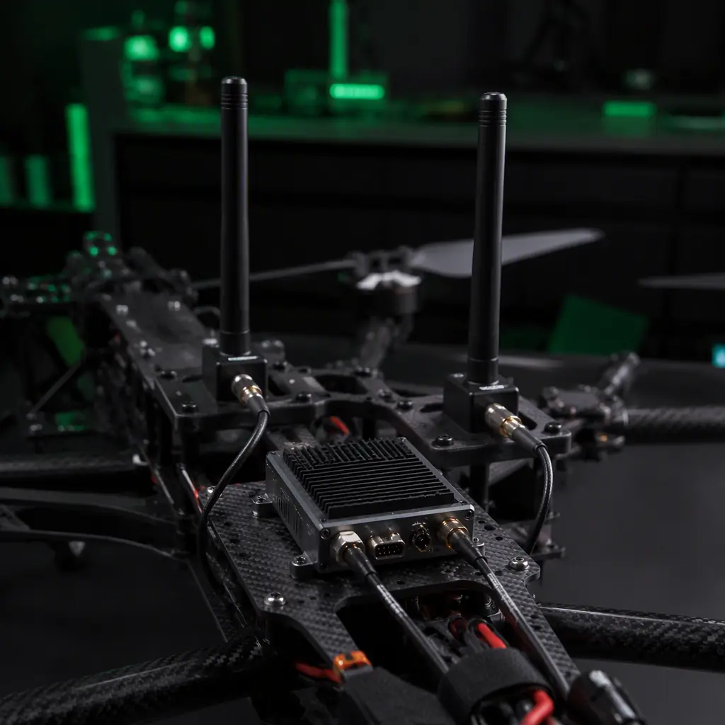 Concept illustration
The BVLOS component procurement checklist
The following ten line items translate the BVLOS architecture into a component-level specification. Each line item names the evidence the procurement team should collect, and the checklist assumes the base platform (airframe, propulsion, flight controller, navigation) is specified separately.
1. Remote ID module. The aircraft shall carry an ASTM F3411-22a compliant remote ID module with broadcast (Wi-Fi Beacon) and network (LTE) capability, integrated with the flight controller position source and the power bus. Verification: the module's declaration of compliance, the integration test report (the broadcast received by a reference receiver at 1 km), and the network registration test.
2. ADS-B In receiver. The aircraft shall carry a 1090 MHz ADS-B In receiver for cooperative traffic. Verification: the receiver's sensitivity and filtering specification, and the measured detection range against live traffic in the operating airspace.
3. Non-cooperative detection. The aircraft shall carry radar and/or EO/IR vision detection with a documented worst-case detection range against a defined target. Verification: the sensor datasheets and the flight test report demonstrating the detection range in the specified visibility.
4. DAA fusion compute. The aircraft shall carry an edge AI compute module (10–50 TOPS class) running the detector and the track fusion, with the inference latency and the tracking update rate documented. Verification: the benchmark report (frames per second, inference latency) and the thermal performance in the airframe. The compute selection is covered in the edge AI and onboard computing guide.
5. Autopilot DAA interface. The flight controller shall support the DAA command interface with a deterministic handover policy between the operator and the DAA system. Verification: the interface documentation and the integration test report. The autopilot selection context is in the ArduPilot vs PX4 guide.
6. Dual-link C2. The aircraft shall carry two independent C2 links (for example, 2.4 GHz digital plus 4G/LTE or 868/915 MHz) with automatic handover, and a documented link budget for the mission range with a defined fade margin. Verification: the measured link performance report and the handover test results.
7. Lost-link behavior. The autopilot shall execute a defined lost-link contingency (return, hold or land) from the onboard state with no operator input. Verification: the lost-link flight test report with the link intentionally terminated.
8. Geofence enforcement. The aircraft shall carry an onboard geofence database with GNSS-based enforcement and a defined breach response. Verification: the geofence test report (a planned geofence crossing at speed) and the position integrity documentation from the redundant navigation stack.
9. Redundant navigation. The aircraft shall carry the redundant navigation stack (multi-GNSS plus IMU fusion with integrity monitoring) required for the position-trusted functions. Verification: the navigation performance report and the GNSS module qualification data.
10. Flight termination and safety architecture. The aircraft shall carry the flight termination channel and the fail-safe architecture defined in the safety case, independent of the primary flight controller. Verification: the FTS test report and the safety and redundancy design documentation.
For the component-level testing and validation practices that verify the BVLOS chain — the link tests, the sensor range tests, the lost-link and geofence flight tests and the acceptance criteria — the UAV propulsion testing and validation guide describes the test bench framework that extends to the avionics and the airspace functions, and the supplier evaluation checklist covers how to verify the evidence chain during a supplier audit.
Explore custom engineering Back to Blog
Continue Reading
UAV Remote ID and BVLOS Compliance Components
The regulatory detail of remote ID — Part 89, ASTM F3411, the module options and the compliance documentation chain for exported platforms.
UAV Sensor Fusion and Redundant Navigation
The navigation stack that the position-trusted BVLOS functions — remote ID, geofencing, DAA track association — depend on for integrity.

UAV Safety and Redundancy Systems
The fail-safe architecture, the redundant avionics and the flight termination design that make the BVLOS contingency set executable.
UAV RF Communication Systems Guide
The frequency planning, the link budget and the coexistence analysis for the dual-link C2 architecture and the remote ID broadcast.
UAV GNSS Module Selection Guide
The multi-GNSS, RTK and integrity features that the position source feeding remote ID, geofencing and DAA must deliver.