
Define
Aircraft type, mission profile and payload requirements.
 Concept illustration
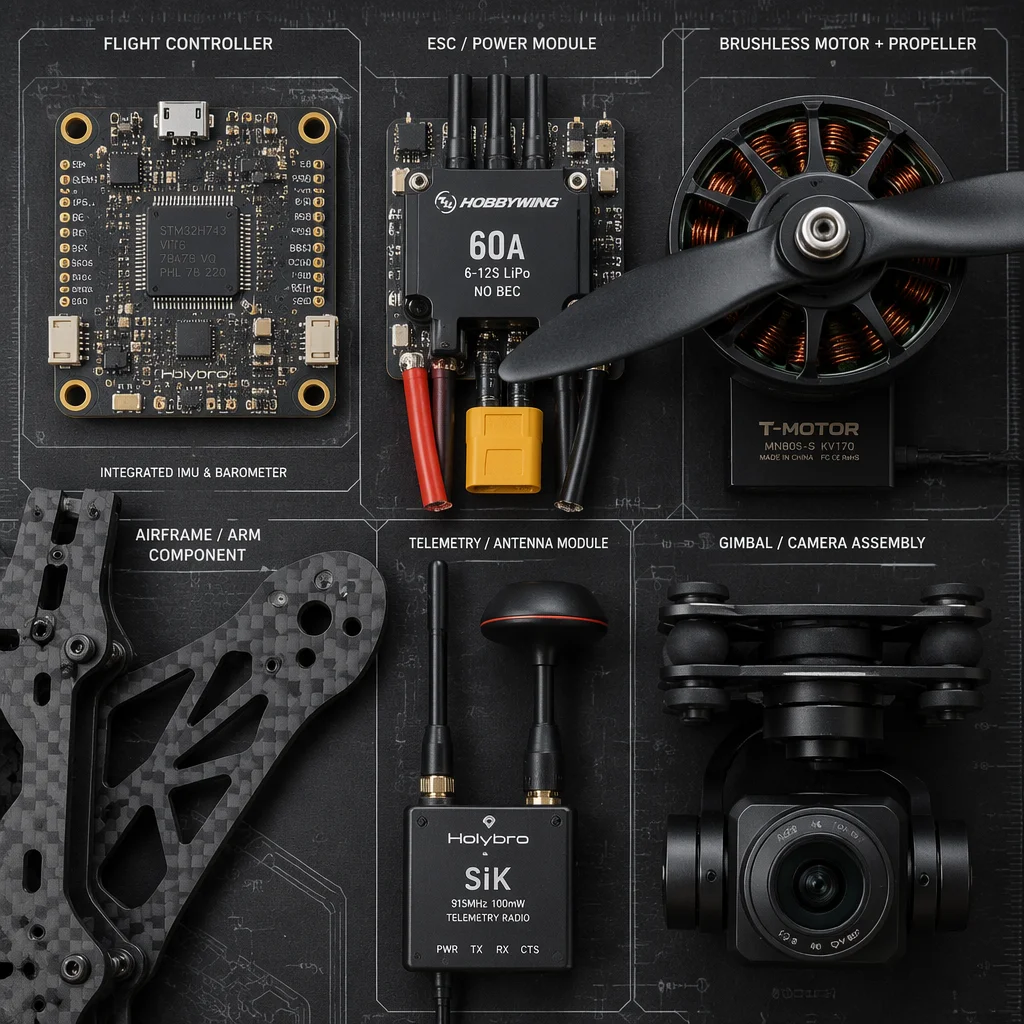
Six component families sourced and configured around system interfaces, so the flight controller, powertrain, structure and payload work as one connected architecture.
Each component layer connects to the others through interfaces, protocol, voltage, mechanical fit and data flow. We organize sourcing so those connections stay visible, not lost between separate catalog pages.
 Concept illustration
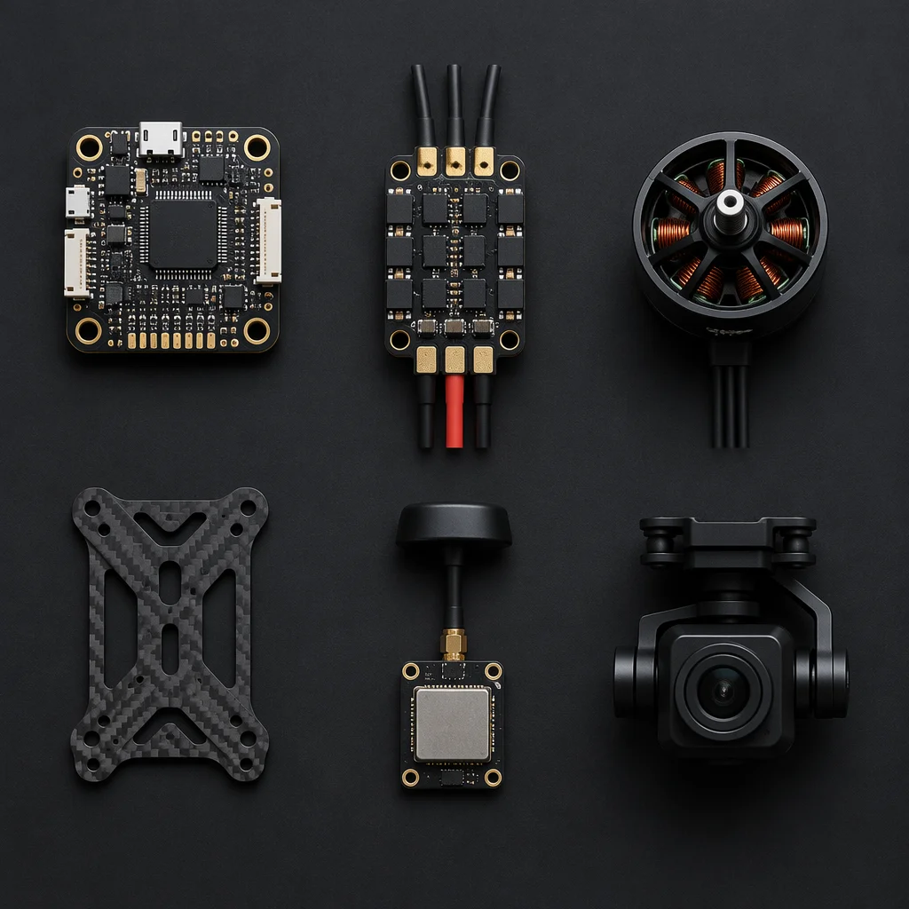
Controllers, sensors, navigation and firmware alignment. The decision layer that reads the aircraft state and issues commands to every other subsystem.
Speed controllers, power distribution, batteries and wiring architecture, the energy path that converts battery voltage into precise motor control.
Motors, propellers and powertrain matching, the thrust layer that turns electrical energy into controlled lift and directional force.
Structures, frames, landing gear and protection. The platform layer that holds the system together under load, vibration and environmental stress.
Radio, telemetry, GPS/GNSS and data links. The signal layer that keeps the aircraft connected to the operator, the ground station and the mission.
Cameras, gimbals, sensors and configured mission sets, the application layer that turns an aircraft into an inspection, mapping or sensing tool.
A flight controller choice determines which ESC protocols are available. Motor selection sets the current draw that the power system must handle. Payload weight and interface shape the airframe and comms architecture. We keep these dependencies visible.
Aircraft type, mission profile and payload requirements.
Flight controller, sensors and firmware architecture.
ESC, battery and distribution matched to the control layer.
Motors and propellers aligned with power and airframe.
Radio, telemetry and positioning for the operational range.
Payload and platform configuration for the application.
Component selection is the starting point. Customization and testing turn parts into a platform.
Translate aircraft type, payload goals and operating environment into a matched component architecture, starting at any layer or depth.
Explore CustomizationPower-path checks, interface verification, parameter review and flight-readiness preparation turn sourced components into a validated system.
Explore TestingStart with a flight controller requirement, a full BOM or a mission concept. We will map the interfaces that connect your build across all six layers.
Each component family has its own cost page. The question a buyer asks at this level is different: when several layers are combined into one engagement, where does the money actually concentrate. The bands below are component build cost across typical industrial platforms, not resale price.
| Layer | Typical share of a matched build | What shifts the share |
|---|---|---|
| Flight control | 8 – 14 percent | Ecosystem choice, sensor set, whether redundant IMUs are specified |
| ESC and power | 12 – 20 percent | Current class, whether a smart power module is included, harness complexity |
| Propulsion | 15 – 24 percent | Motor class, thrust-to-weight target, propeller material and count |
| Airframe and structure | 22 – 34 percent | Wheelbase, ply schedule, machined interface count, test article |
| Communications | 7 – 13 percent | Range class, whether redundant links are required, antenna customisation |
| Payload and gimbals | 10 – 30 percent | Sensor class, stabilisation requirement, mission-set configuration |
The share that surprises buyers most is airframe and structure. On a fixed-wing or large multirotor it routinely exceeds the electronics combined, because structure carries machining, tooling and structural validation rather than catalogue parts. Teams that budget from an electronics BOM alone under-provide this layer more than any other.
When several families are sourced together, the obligation boundaries have to be drawn once for the whole stack, or each family is read independently and interfaces fall between them.
| Item | Supplier responsibility | Operator responsibility |
|---|---|---|
| Cross-layer interface definition | Document voltage, current, protocol and mechanical fit at every layer boundary | Confirm the mission the combined stack must survive |
| Matched-stack compatibility | Verify the selected families interoperate before shipping | Confirm the intended build depth and target cost band |
| Firmware and parameter baseline | Provide a documented baseline across control, power and signal layers | Own the final parameters once in its own operating environment |
| Bench and flight-readiness test | Run the agreed combined checks and record results | Provide the flight-test environment and accept the airworthiness call |
| Configuration control | Freeze a combined build revision and trace every change | Maintain the revision during field repair |
| Regulatory documentation | Declare the standards each family is tested to | Own the aircraft operator certificate and airspace authorisation |
The failure that costs the most is a matched stack where each family is compliant and the combination is not verified. An ESC that meets its own specification into a motor the supplier never paired it with is how a build passes every incoming inspection and still fails on the bench.
Both are published in full on our projects pages. They show how the layers above come together on a real aircraft rather than on a component list.
One build concentrates cost in payload efficiency, the other in propulsion and power margin. Reading your mission against the nearer of the two tells you which table row your own budget will actually be driven by.
These points let a first quotation come back as a matched architecture rather than a component list.
Because the layers are priced as shares of one build, a target cost band is more useful here than on any single-family page. It lets each layer be sized against the others instead of optimised in isolation.