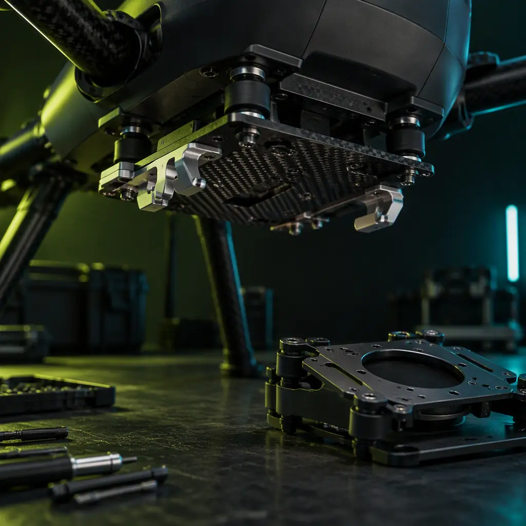
The failure mode that costs the most is the quiet one. An aircraft is commissioned in a single configuration, flown through acceptance, and handed over with a survey report or an inspection dataset that becomes the reference for every subsequent flight. Eighteen months later a second payload is added. The mount is changed, the payload is swapped weekly between two heads, and the operator notices that the data from the LiDAR flights no longer georegisters against the photogrammetry flights the way it used to — not dramatically, but by enough that the two datasets have to be processed independently instead of in the same coordinate frame. Nothing has failed. The airframe is sound, the sensors are within specification, and every component passes its bench test. What changed is that the interface stopped returning the payload to the same place, and nobody had written a number for how much that mattered.
A mounting interface is not a bracket. It is a mechanical contract that fixes six degrees of freedom, transfers a defined set of loads, decides where vibration is attentuated, and has a finite number of mating cycles before its own tolerances have moved. Every one of those properties is a procurement decision, and each one has a counterpart on the payload side that the airframe supplier may not own. The payload integration guide covers the electrical, weight and CG side of adding a head to an aircraft; the release mechanism guide covers the actuator that lets go. This article covers the joint in between, which is the one that decides whether the aircraft can actually be reconfigured.
What has to repeat, and what does not
The mistake that produces unusable multi-payload data is treating every degrees-of-freedom as equally important. They are not, and the ones that matter depend entirely on what the payload measures and how its data is georeferenced.
A camera or LiDAR carried by a gimbal does not depend on the interface for its pointing accuracy. The gimbal measures and corrects its own orientation, so a mounting repeatability of a couple of millimetres is absorbed by the stabilisation loop and never reaches the data. Its real requirement on the interface is stiffness at the gimbal base, because every micron of interface compliance shows up as a lag the gimbal has to chase, and that lag degrades the georeferencing more than the offset does. A fixed-mount survey sensor is the opposite case. A downward-facing multispectral or photogrammetry camera with no gimbal is rigidly referenced to the airframe and to the GNSS/IMU, so its lever arm — the vector from the IMU's measurement point to the camera's optical centre — is a number in the photogrammetric solution. If the interface lets that lever arm change between flights, the solution is wrong by that amount and the error is applied to every image in the set.
The useful discipline is to write a repeatability budget as two separate numbers rather than one. A positional repeatability figure describes whether the payload comes back to the same point within the airframe coordinate system on reinstallation, typically expressed as an allowable displacement of the payload's datum in three axes. A rotational repeatability figure describes whether its axes come back to the same orientation — this is the one that is usually ignored and usually the one that bites, because a payload that is 2 mm off in translation but 0.05° off in yaw feeds a heading error into a georeferenced product that gets worse with altitude. A working split for a survey-grade fixed-mount payload is on the order of ±0.5 mm in translation and better than 0.1° in each rotation relative to the airframe datum, quoted per removal-and-refit cycle and not as a one-off installation tolerance. For a gimballed payload, the same numbers can loosen by an order of magnitude without consequence, and the budget should say so explicitly so that nobody over-specifies a cheap interface and then wonders why it costs more than the camera.
| Payload class | Positional repeatability | Rotational repeatability | What actually drives the data |
|---|---|---|---|
| Gimballed camera / LiDAR | Loose (±2-3 mm) | Loose | Interface stiffness at the gimbal base; the gimbal absorbs pointing error itself |
| Fixed-mount survey sensor | Tight (±0.5 mm) | Very tight (<0.1°) | Stability of the IMU-to-sensor lever arm across the whole flight set |
| Drop / delivery payload | Loose | Loose | Load-path capacity and release reliability, not geometry |
| Sampling or probe payload | Moderate | Moderate | Contact force path — repeatability only matters where the tool touches the target |
 The interface decides the lever arm; the lever arm decides the georeferencing
Four mounting families and what each is honestly good at
Almost every UAV payload attachment reduces to one of four families. They differ in what they constrain, who supplies the mating half, and how their wear-out manifests — and a programme that mixes them across a fleet inherits the worst properties of each.
A rail system constrains the payload to slide along one axis and relies on an end stop for the second. It is fast, tolerant of small misalignment during installation, and well suited to payloads that need to be slid fore and aft to trim CG. Its weakness is that the mate between rail and carriage has clearance in every direction except the constrained one, so its rotational repeatability is poor: a rail-mounted survey sensor will not return to the same yaw angle reliably, and the rail's own carriage will develop play as its bearing surfaces wear. Rails are the right answer for gimballed and delivery payloads and the wrong answer for a rigidly referenced sensor.
A quick-release plate is the family most people mean when they say "payload mount." A plate pair with locating pins and a latch that pulls the two halves into hard contact can achieve excellent repeatability, because the pins fix translation and rotation while the latch provides a repeatable seating force. Its behaviour depends almost entirely on how the seating force is generated. A spring-over-centre latch produces a force that varies with its own wear and with ambient temperature; a screw-clamp or over-centre with a positive stop produces a much more consistent seating force. The plate itself rarely wears, but the latch mechanism does, and that is the topic of a section below.
A hardpoint bolt pattern is the family with the best repeatability and the worst field ergonomics. A defined bolt pattern with dowel or shoulder-located dowels pins the payload in all six degrees of freedom with a repeatability limited only by the fit of the locating feature, commonly in the tens of microns if the pattern uses a proper shoulder dowel rather than relying on the bolts themselves to locate. The cost is time: four or six fasteners torqued to a preload specification is a workshop operation, not a field one, and every removal consumes fastener and thread life. For an aircraft that changes payload once a programme and needs survey-grade repeatability, this is the correct and cheapest answer. For a platform with a weekly payload rotation it is the wrong tool.
A gimbal damper mount is not really a mounting family so much as a suspension. It constrains the gimbal through an elastomer interface deliberately designed to attenuate high-frequency vibration while passing the steady loads. Its repeatability is the poorest of the four by design, which is acceptable because the gimbal corrects its own pointing, and its wear-out mechanism is the elastomer itself — a hardening and compression-set process that changes the transmissibility the mount was selected for. The vibration isolation guide covers the material side of that problem in depth.
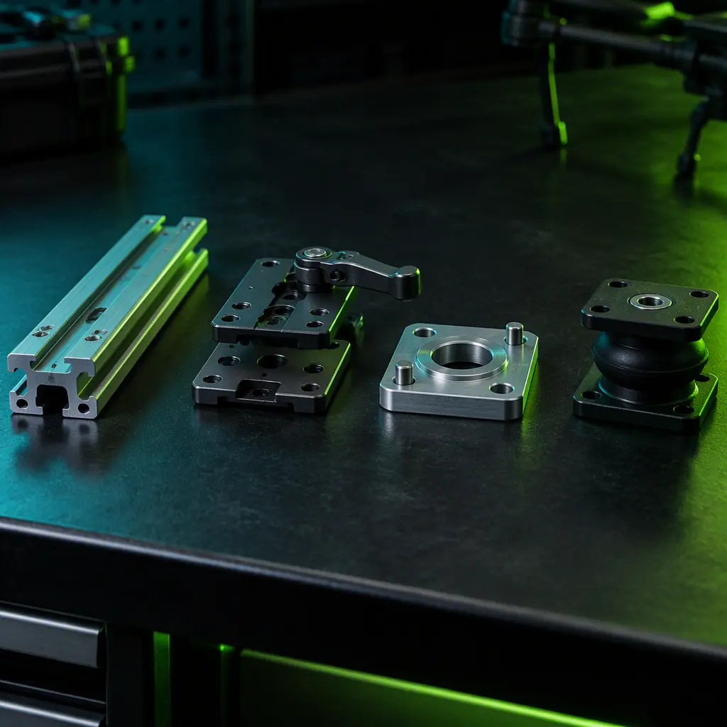 Rail, quick-release plate, hardpoint pattern, damper mount
Who owns the load path when the payload is not the airframe's
An interface that meets its repeatability budget can still be a structural failure waiting for the right gust, and the reason is almost always that nobody defined who owns the margin. The airframe supplier sizes the airframe for a design payload case. The payload supplier sizes the payload for its own internal loads. The interface in between is frequently supplied by a third party and designed against a catalogue load rating that says nothing about the airframe's load case or the payload's inertial properties.
The fix is to require the interface to be qualified against a defined interface load case that is generated from the aircraft, not from the bracket. That case has three parts. The first is the limit load the interface must carry without permanent deformation, derived from the design manoeuvre and gust envelope plus the payload's mass and the lever arm from the payload's centre of gravity to the interface plane. The second is the dynamic amplification that the airframe's own response adds to that load — a payload at the end of a flexible boom absorbs landing and turbulence events through a structural path with its own resonant amplification, and an interface sized only on static load will be under-designed by exactly that factor. The third is the fatigue spectrum: how many of those load cycles the interface will see over its life, which for a component flown daily is a number in the tens of thousands within a couple of years.
Two consequences follow that a buyer can write into a specification. First, a bearing-style interface transfers load through discrete contact points — the latch lands, the pin bores, the rail carriage — and each of those points sees a serious bearing stress that must be checked against the material's allowable for that joint type rather than against general yield. Second, the fastener preload on any bolted interface is a design property, not an installation preference. A bolted joint that is not preloaded enough lets the two halves separate under cyclic load and the bolt then carries the entire load in bending, which is how a bracket with a generous safety factor on paper cracks at a thread root in service. Specifying a torque is not sufficient on its own; the specification should state the target preload, the friction condition assumed in the torque-preload relationship, and the thread lubricant intended, because those three together determine whether the number on the torque wrench means anything. The airframe structural design guide covers how the load path is traced through the airframe proper.
Isolation belongs at the interface, not on the payload
Where vibration isolation is installed determines what it protects, and the default choice made by most teams protects the wrong thing. An isolator placed between the payload and its mount attenuates vibration reaching the payload — which is what a gimbal needs, and which is why it is common. But it does nothing for the airframe, and it introduces a compliance in the load path that makes the payload's own position less determinate. For a gimballed payload that trade is fine. For everything else it is usually backwards.
Placing the isolation at the interface, on the airframe side of the joint, decouples the payload's mass from the airframe's response and changes the airframe's modal behaviour. This is often the higher-value choice, because the vibration that degrades sensor data and fatigues brackets usually originates in propulsion and is transmitted through the airframe, not the reverse. Isolating at the interface means the payload no longer participates in the airframe's bending modes as a lumped mass, which can move a resonant frequency out of the rotor band entirely — a structural improvement, not just a sensor-quality one. The cost is that the isolator now carries the full payload load through an elastomer or wire-rope element, and its stiffness becomes part of the interface's positional repeatability. An isolator with 2 mm of deflection under 1 g is a soft interface by definition, so this choice and a tight repeatability budget are in tension and one of them has to win.
The tension resolves cleanly if the two functions are separated. Use a hard, determinate locating feature — dowels, pins, a machined shoulder — to fix position in the plane that matters, and a soft element in the third axis only if the dominant vibration is normal to the mounting plane. A payload mounted on three dowels with axial elastomer compression elements between the faces is positioned laterally with the repeatability of the dowel fit while being isolated in the direction that carries the most rotor energy. This is a more expensive interface than a plain plate, and it is the only arrangement that satisfies both a survey-grade repeatability budget and a useful vibration isolation requirement at the same time.
Mating cycles: the latch is a wear-out item
A quick-release latch is a mechanism with sliding and rotating contact surfaces, and like every such mechanism it has a finite life expressed in cycles rather than hours. A properly rated quick-release assembly for UAV payload use should be specified with a mating cycle life of 5,000 to 10,000 cycles, meaning the number of full engage-and-release operations the latch can complete while still holding its specified seating force and positional repeatability. Below that rating, the two failure modes that appear are a seating force that drifts downward as the contact surfaces wear, so the payload is no longer pulled into hard contact and repeatability degrades quietly, and a latching surface that develops enough wear to allow a small relative movement under load, which shows up as a payload that is secure in static check but moves under gust loading.
This makes the latch a scheduled replacement item, which is a procurement consequence most programmes miss. Three requirements follow. The latch life should be quoted by the supplier together with the test basis — how many cycles were run, at what load, and what the acceptance criterion was for seating force and repeatability at the end — because a cycle rating without a stated degradation limit is a number without a meaning. The interface should be inspectable at the periodic maintenance interval, which requires that the latch's engagement be visible or measurable without disassembly; a latch buried inside a closed housing cannot be assessed and will therefore be replaced on a calendar guess. And the latch should be separately replaceable from the plate, because the plate's locating features will outlast several latch mechanisms and replacing the whole assembly every time is both wasteful and a chance to introduce a new part number into a qualified configuration.
Well before a latch is worn out, its condition is observable in the data if anyone is looking. The diagnostic is a repeat of a reference flight after each payload swap, comparing the payload's indicated attitude against the airframe's own IMU at a moment when the aircraft is level and stationary. A slowly growing offset between the two, trending in one direction across successive swaps rather than varying randomly, is a seating-tolerance problem in the interface and not a sensor drift. Random scatter around zero across swaps is normal and is the signature of a healthy interface operating within its repeatability budget; a monotonic trend is the signature of wear. Logging this one number at every payload change turns the latch from an item that fails without warning into one with a visible wear trend, and it costs nothing beyond a discipline of doing the same check the same way each time.
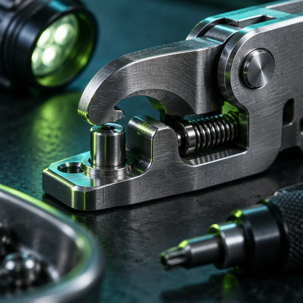 Quote the cycle life with its test basis, not on its own
Procurement clauses for mounting hardware
The interface is cheap relative to the payload it carries and cheap relative to the cost of a dataset that has to be reprocessed, which is exactly why it is specified loosely. The clauses that prevent that are short enough to sit in the same document as the performance requirements, and they should be written for the interface as a system rather than for its parts.
First, a repeatability specification stated per removal-and-refit cycle, broken into translation and rotation and referenced to a named airframe datum, with the measurement method defined so that both parties can test it the same way. Second, the interface load case, generated from the aircraft's design envelope and the payload's mass and centre of gravity, including the dynamic amplification factor and the fatigue cycle count, with the requirement that the interface be qualified to that case and not to a catalogue rating. Third, joint preload requirements for any bolted interface: target preload, assumed friction condition, intended lubricant and the inspection method that confirms it. Fourth, the mating cycle rating with its test basis, plus the acceptance criteria for seating force and repeatability at end of life. Fifth, maintenance information: which surfaces wear, how to inspect them without removing the interface, and what the replacement procedure is. Sixth, interchangeability, so that a replacement plate or latch substituted months later produces the same interface geometry and therefore the same lever arm and the same data quality.
The bottom line: decide the repeatability budget from what the payload actually measures rather than from a generic tolerance, pick the mounting family that matches how often the payload will actually be swapped, own the interface load case at the airframe rather than inheriting a bracket's catalogue rating, put the isolation on the side that needs protecting with position fixed by a hard locating feature, and treat the latch as a life-limited item with a cycle rating that comes with its test basis. EMS Drone supplies UAV airframe and payload interface hardware — quick-release assemblies, location-pinned mounting plates, hardpoint patterns and isolated interface modules — and reviews each payload's lever arm and mass properties to set the interface load case before the part is made. Send us your airframe configuration, the payloads the aircraft has to carry and how often they change over, and we will return the interface recommendation, the repeatability and load-case specification, and the procurement clauses that hold a supplier to both.
Explore Capabilities Back to Blog
Continue Reading
Payload Integration
Electrical, weight and CG integration for a new payload head.

Release Mechanisms
Actuator families, failsafe redundancy and drop testing.
Vibration Isolation
Mount families, the root-2 rule and isolator selection.
Airframe Structures
Stiffness, modal margin and how loads travel through a frame.