
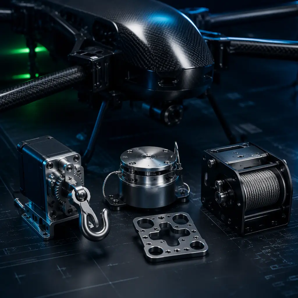
Most payload engineering effort goes into sensors, gimbals and data links, the systems that see, stabilize and transmit. Release mechanisms sit at the opposite end of the payload chain: they are electromechanical, load-bearing, and they operate for a few hundred milliseconds at the moment the mission output happens. A sensor payload that drifts slightly still produces usable data; a release that fails produces a lost package, a damaged airframe or an unsafe operation. The payload integration guide covers the full payload chain; this guide goes deep on the release and actuation subsystem, the component category where delivery, emergency and research missions succeed or fail.
The actuation families: four ways to let go of a payload
Every UAV release mechanism falls into one of four actuation families, and the choice between them is driven by payload weight, release precision, fail-safe direction and environmental range. There is no universal mechanism. The right one is the one whose failure mode matches the mission's acceptable risk.
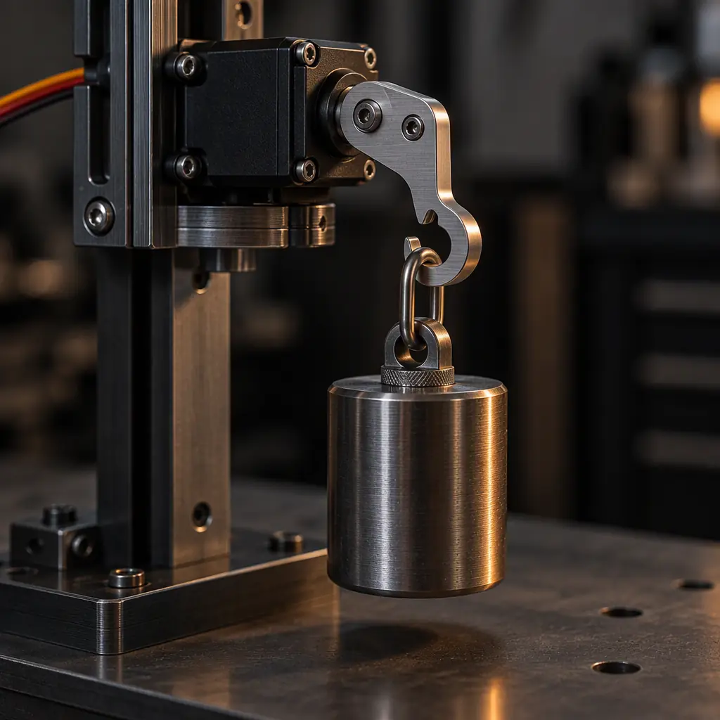
Servo-driven hooks and latches. A metal-gear servo rotates a hook, pin or latch arm to release a payload suspended from a loop, rail or cradle. This is the workhorse of the 1–10 kg delivery class. A 25 kg·cm metal-gear servo holds a latched load with large margin, draws 500 mA–2 A at stall, and releases in 200–500 ms depending on servo speed and travel. The engineering is in the latch geometry: the hook must hold without binding under the load path, and the release angle must clear the payload loop completely. A partial release that re-catches is the classic failure mode.
Electro-magnet couplers. A payload carries a steel or ferrite capture plate; an electro-magnet in the airframe holds it with a specified holding force, and the payload drops the instant the coil is de-energized. Holding force scales with magnet size, a 40 mm disc magnet holds 20–50 kg against a flat, clean steel plate, and there are no moving parts, no wear and no release-time ambiguity: release is effectively instantaneous. The costs: holding force is sensitive to plate flatness, contamination and off-axis loading; the magnetic field can disturb a nearby magnetometer if the mount is not shielded or spaced; and the mechanism has a hard failsafe direction decision (see the redundancy section below).
Winch and lowering systems. For fragile, heavy or high-value payloads, the answer is not a drop but a controlled descent. A motorized drum pays out a line at 0.5–2 m/s to lower a 5–50 kg load to a landing zone, then releases it on contact or returns for the next cycle. Winches add real subsystems: line management to prevent snagging, pay-out control with brake logic, pendulum damping for windy conditions, and a cut-down device, including typically a DC-motor line cutter, as the emergency release path.
Pyrotechnic initiators and line-cutters. Parachute deployment, emergency jettison and defense payloads use electrically fired initiators or explosive cutters. These are fast (milliseconds), compact and highly reliable, but they introduce ordnance handling, transport restrictions and regulatory overhead that most commercial operations cannot justify. Which is why the DC-motor line cutter (a small geared motor that shears a rated line) has become the legal and practical alternative for parachute and winch emergency release.
| Mechanism | Typical load | Release time | Moving parts | Power draw | Typical use |
|---|---|---|---|---|---|
| Servo hook / latch | 1–10 kg | 200–500 ms | 1 servo + latch | 0.5–2 A stall | Delivery, agriculture |
| Electro-magnet coupler | Up to 50 kg | <50 ms | None | 0.2–2 A hold | Research drops, rescue |
| Solenoid pin | 0.1–2 kg | 10–100 ms | 1 pin + spring | 0.3–1 A pulse | Light sensor probes |
| Winch / lowering | 5–50 kg | Seconds (descent) | Motor, drum, line | 5–20 A inrush | Medical, cargo delivery |
| Pyrotechnic / line-cutter | Any (shear rated) | <50 ms | 1 blade / initiator | 1–5 A pulse | Parachute, jettison, defense |
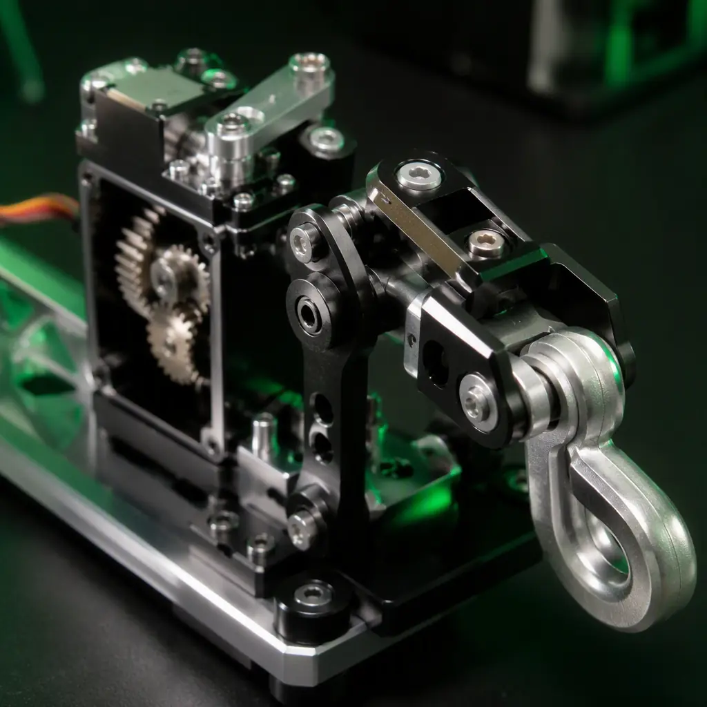 Servo latch detail
Electrical integration: the release event is a current spike, not a signal
The release event is the highest-current transient in the payload chain, and it happens at exactly the moment the flight controller has the least spare headroom. A servo stalls at 0.5–2 A while the control loop is managing the CG shift from the load leaving the aircraft; a winch motor inrush is 5–20 A; an initiator pulse is 1–5 A for 10–50 ms. On a shared 5 V or battery rail, that spike can brown out the flight controller, the GNSS receiver or the telemetry link precisely when the mission needs them most.
- Isolated power rail. The release mechanism should draw from its own supply rail or a distribution output with independent protection, not from the flight controller's regulated rail. The payload power budgeting guide covers the regulator and filtering architecture for exactly this split.
- Bulk capacitance at the mechanism. A 1000 µF low-ESR capacitor at the mechanism input absorbs the inrush so the spike never propagates upstream. This is the cheapest brownout insurance in the system.
- Command path separation. The release command should be a dedicated RC channel, a CAN frame or a discrete GPIO, not multiplexed onto the same serial line as critical telemetry. Log the release command with flight telemetry so every drop has a timestamped record.
- Current sensing for verification. A current-sense resistor or hall sensor on the actuator tells the flight controller whether the mechanism actually moved. The feedback that makes a "release confirmed" state possible.
Wiring discipline matters here more than in almost any other subsystem: the harness between the distribution board and the mechanism is a fatigue and chafe point on every flight cycle, and the connectors and power distribution guide covers the gauge, fuse and connector selection for high-current actuation loads.
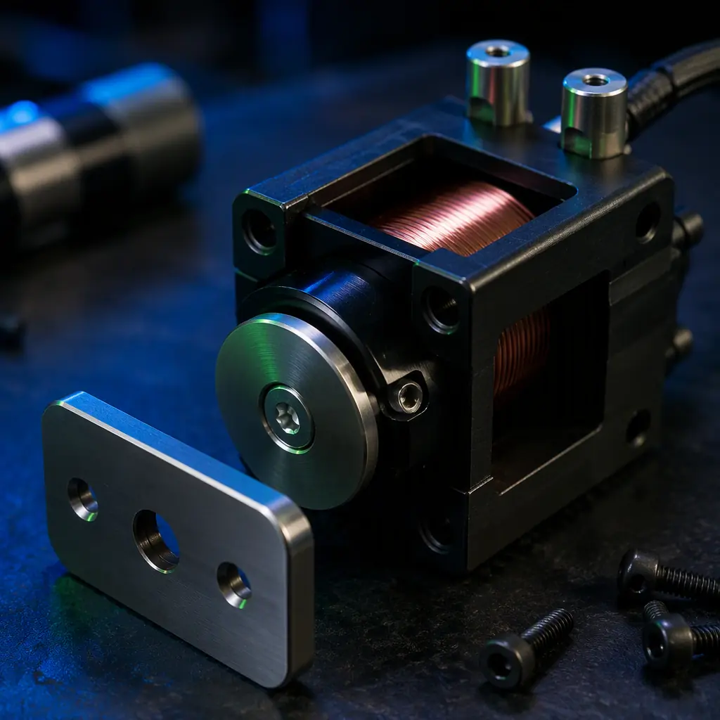 Electro-magnet coupler
Mechanical integration: the CG shift and the load path
Releasing a payload is a sudden change to the aircraft's mass distribution, and the flight controller has to absorb it in one control cycle. A 1 kg payload at a 200 mm moment arm from the CG is a 0.2 kg·m step in pitch or roll authority demand. Within the authority of most industrial flight controllers at nominal throttle, but a real disturbance at hover in wind, and a genuine upset risk if the release is asymmetric or the load swings. The mechanical rules:
- Mount to hardpoints, not panels. The release mechanism carries the full payload load through the flight envelope. Random vibration at 6 G RMS in the 20–500 Hz band is typical for industrial airframes. The mechanism mounts to the airframe hardpoints or a load-spreading plate, never to a thin skin or a payload bay wall.
- Two-point retention for heavier loads. Above 5 kg, a single-point latch multiplies the moment on the mount and allows the load to rotate under asymmetric loading. Two-point retention with a sequenced release (aft first, then forward) drops the load flat instead of tipping it.
- Latch preload and locking geometry. The latch must hold through vibration without releasing or re-catching. Preload the latch against its stop and design the hook face so vibration loads push it further into the locked position, never toward the release angle.
- Test the release in the real attitude. A release that works on the bench can fail at 60° bank or under a 10 m/s wind vector, the load trails, swings or catches on the landing gear. Flight-test the release envelope, not just the hover case.
The payload integration guide frames the weight, CG and vibration budget that the release mechanism must fit inside. The release subsystem is specified against the same integration constraints as the payload itself.
Redundancy and failsafe: what happens when the release does not fire
Every release mechanism has a failure direction, and the design question is which failure is acceptable: an accidental release over a populated area is a safety event; a failure to release over a landing zone is a lost mission. The two are managed differently, and the mechanism choice locks in the answer.
- Failsafe direction. A de-energize-to-release mechanism (electro-magnet, spring-loaded pin) drops the payload on power loss. Correct for research probes and rescue drops where the payload must always come off, dangerous for delivery where an RC or battery failure mid-route would drop cargo on the wrong coordinates. An energize-to-release mechanism (servo, motor) holds the load on power loss. Correct for delivery, but it needs a backup release path for the "release commanded, mechanism dead" case.
- Dual-channel redundancy. The mission-critical release should have two independent actuation paths: the primary mechanism plus a line-cutter, a second latch or a pyrotechnic backup. The backup fires on a separate command channel and draws from a separate rail, so a single electrical failure cannot pin the payload to the airframe.
- Watchdog verification. If the release command is sent and no feedback (limit switch, current sense, hall sensor) confirms motion within a timeout window: typically 500 ms to 1 s, the backup path fires automatically, or the system returns to a safe state and aborts.
- Low-battery derating. Actuator torque and solenoid hold force are voltage-dependent, and servo torque falls with pack voltage. Specify the mechanism's operating range against the flight controller's low-voltage cutoff: if the FC cuts the main pack at 3.5 V/cell, the release mechanism must still actuate at that voltage, or it gets its own supply.
The same redundancy logic that governs flight control and power systems applies to the release subsystem, the safety and redundancy systems guide lays out the architecture-level framework that release failsafes plug into.
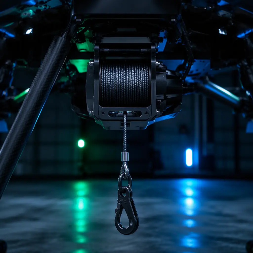 Winch lowering system
Testing the release: drop tests, cycle life and temperature
A release mechanism is only as trustworthy as its test record, and the tests are not optional. They are the deliverable a procurement team should demand alongside the hardware. The test set that matters:
- Drop testing from hover. Release the rated payload mass from 3–10 m hover altitude, with high-speed video at 240 fps or higher to verify release time, trajectory and that the payload does not swing into the airframe or the landing gear. Repeat across the throttle range, not just idle hover.
- Forward-flight releases. At 10–20 m/s cruise, the payload trails behind the aircraft before falling. The release point must account for the drag offset, and the mechanism must not re-catch the load on the way out. This is the test that catches most integration errors.
- Cycle life. Servo mechanisms are rated for finite cycles. 500–1,000 cycles is a reasonable expectation for a delivery latch before wear inspection, with the hook, pin and pivot checked for play. Winch line is a consumable with a documented replacement interval, not a fit-and-forget part.
- Temperature extremes. The UAV operating envelope is typically -20 °C to +50 °C. Servo torque derates at low temperature, lubricant viscosity changes, and electro-magnet holding force shifts with coil resistance, test the release at both extremes, not just at bench temperature.
- Random vibration soak. A 2-hour random vibration soak at the airframe's rated spectrum, followed by a functional release test, proves the latch holds in flight vibration and still releases on command. The propulsion testing and validation guide applies the same test philosophy to the propulsion chain.
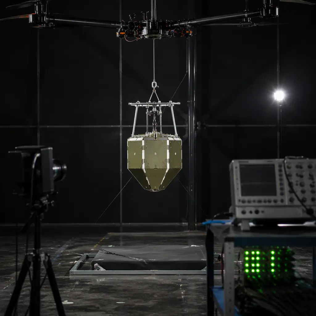 Drop test rig
Selecting the mechanism by mission
The mechanism choice follows the mission profile, and the pattern is consistent across the industry verticals:
| Mission | Payload class | Recommended mechanism | Critical requirement |
|---|---|---|---|
| Cargo delivery | 1–10 kg | Servo hook, two-point for >5 kg | Energize-to-hold, dual-channel, landing-zone accuracy |
| Medical / emergency supply | 1–5 kg | Winch with line-cutter backup | Controlled descent, contact release, cut-down failsafe |
| Search and rescue | 0.5–5 kg | Electro-magnet or servo hook | De-energize-to-release, manual GCS override |
| Research sensor drops | 0.1–2 kg | Solenoid pin or electro-magnet | Timestamped release, current verification |
| Agriculture tank dump | 5–25 kg | Large servo valve or electro-magnet | Corrosion resistance, rapid full-dump |
| Defense jettison / chaff | 0.5–5 kg | Pyrotechnic initiator | Ordnance handling, redundant initiators |
As a sizing rule of thumb: under 1 kg, electro-magnet or solenoid pin; 1–10 kg, servo hook; 5–50 kg or fragile cargo, winch; emergency jettison or parachute, line-cutter or pyrotechnic with a documented handling chain. For delivery fleets, the logistics and delivery components guide shows how the release subsystem fits the full delivery operation, and the public safety components guide does the same for rescue and emergency platforms.
Procurement checklist: the RFQ clauses for release mechanisms
Because release mechanisms are the least specified payload subsystem, the RFQ is where most programs go wrong, vague requirements come back as vague compliance statements. The clauses that make a release RFQ enforceable:
1. Mechanism type and rated load. The actuation family, the rated static hold and the rated dynamic load with a stated safety factor (2:1 minimum for delivery). Verification: the load-rating test report.
2. Electrical interface. Operating voltage range (including at FC low-voltage cutoff), peak and hold current, command interface (RC, CAN, GPIO) and the wiring diagram. Verification: measured current waveforms from the sample test.
3. Failsafe and redundancy. The stated failure direction, the backup release path and the watchdog behavior. Verification: a fault-injection test report (simulated power loss, simulated command loss).
4. Testing requirement. Drop tests from hover and forward flight, cycle-life rating, temperature extremes and vibration soak, with the test data delivered, not summarized. Verification: raw test logs.
5. Environmental range. Temperature, humidity, IP rating and corrosion resistance matched to the mission profile, the same specification discipline as the agriculture components guide applies to chemical exposure.
6. Documentation and support. Wiring diagrams, maintenance intervals, consumable replacement schedule and integration support for the release command path. Verification: the documentation package.
The decision, in one line: choose the mechanism whose failure direction matches the mission's acceptable risk, isolate its power, design the latch geometry against vibration, add a backup release path, and demand the drop-test and cycle-life data in the RFQ. EMS Drone supplies release mechanisms, matched actuation electronics and integration testing for delivery, rescue and research platforms. Send the mission profile and the payload mass, and we will respond with the mechanism selection, the wiring architecture and the test plan for a release system that fires when it must and holds when it should.
Cost structure: where the release-system budget actually goes
Release systems are rarely the largest line on a UAV bill of materials, but they are among the most expensive per gram, because every dollar spent here buys failure containment rather than performance. The table below shows the cost segmentation we see on representative multirotor cargo and survey platforms in the 5-25 kg MTOW class, expressed as a share of the release subsystem total rather than absolute currency, since the split holds across suppliers and currencies while the absolute numbers do not.
| Cost line | Typical share | What drives it up | Where buyers get surprised |
|---|---|---|---|
| Actuator hardware | 18-25% | Torque margin, metal gear train, holding force at zero power | A cheap servo is the single most common cause of a release that works on the bench and fails in wind |
| Redundancy and monitoring | 15-22% | Second channel, position feedback, continuity sensing, independent inhibit | Frequently cut during cost review, then specified again after the first in-flight anomaly |
| Mechanical interface and structure | 20-28% | Machined hooks, rails, hard points, load-path reinforcement into the airframe | Airframe reinforcement is owned by a different team and is often not budgeted in the release system at all |
| Wiring, connectors and power conditioning | 10-15% | Inrush-tolerant connectors, separate supply rail, filtering | Sharing a rail with avionics is the cheapest-looking decision and the most expensive in service |
| Test and qualification | 12-18% | Drop tests, cycle-life runs, thermal cycling, retained samples | The line most often deferred and the line that determines whether the unit survives year two |
| Documentation, spares and support | 8-12% | Interface control drawings, spare actuator kits, field-replacement procedure | Skipped on prototype buys; becomes a procurement crisis on the first fleet order |
The line that is underestimated most consistently is the mechanical interface into the airframe, not the actuator. A release mechanism that passes every bench cycle test can still fail operationally because the load path from the hook into the airframe was never structurally reinforced, so the hook survives while the mounting frame deforms and the payload shifts against the release gate. Buyers who budget the actuator carefully and treat the interface as a bracket detail are the ones who end up re-engineering after the first flight.
Responsibility split: what the supplier owns and what the operator owns
Release-system failures are unusual in that the root cause is very often a boundary that nobody owned rather than a component that failed. The split below reflects how we divide responsibility on release-mechanism supply, and it is worth writing into the purchase contract explicitly because the default assumption on each side is usually wrong.
| Item | Supplier responsibility | Operator responsibility |
|---|---|---|
| Actuator holding force and cycle rating | Publish verified force figures at rated voltage, with derating curve for temperature | Verify the actual static load and the worst-case dynamic load at the release gate |
| Electrical characteristics | Provide inrush current, steady-state current, and minimum pulse width to guarantee release | Size the supply rail and wiring for the inrush figure, not the steady-state figure |
| Interface geometry | Deliver an interface control drawing with tolerances and hard-point locations | Confirm the airframe reinforcement is designed for the transmitted load, not just the hook bolt pattern |
| Failsafe behaviour | State whether the mechanism is fail-safe, fail-locked, or state-retaining on power loss | Verify the declared behaviour matches the mission-safety case, and document the recovery procedure |
| Cycle-life evidence | Supply cycle-life test data with the test fixture description and pass criteria | Retain the lot records and decide the replacement interval rather than running to failure |
| Firmware and configuration changes | Notify the operator of any firmware change affecting release timing or failsafe logic, and provide the updated qualification evidence | Re-qualify the release system after any firmware change that alters timing, arming logic or failsafe behaviour, before returning the aircraft to service |
The firmware clause deserves particular attention. Release timing is frequently implemented in the flight-controller firmware, which means a routine firmware update can change the arming delay, the pulse width sent to the actuator, or the behaviour on loss of link, without any hardware change and often without the release system appearing on the change-impact list. On platforms carrying anything that presents a hazard on the ground, a firmware change that touches release logic should trigger re-qualification: repeat the drop tests, re-verify the failsafe path, and re-run the arming interlock checks before the aircraft is released to the flight line. Treating firmware as outside the release system's qualification boundary is the most common way a previously validated system becomes an unvalidated one.
Two real builds: release requirements that came from the airframe
The numbers below come from two platforms we built and documented rather than from a specification sheet, and they illustrate how release-system requirements are usually set by the airframe and the mission, not by the actuator catalogue.
Reference build A: a 30 L agricultural sprayer at roughly 25 kg MTOW
The spray platform is an X8 coaxial layout on a 1600 mm wheelbase with carbon-fibre tube arms of 30 mm diameter and CNC aluminium motor mounts, a 350 mm ground clearance undercarriage and a 1800 mm four-nozzle boom carrying 1.0 mm ceramic hollow-cone nozzles that produce 120-180 µm droplets. It flies 12-15 minutes per tank. The release-relevant lesson is the load path: the tank and boom assembly transmit a distributed load into the centre frame, and the same structural members carry the landing loads and the release hard points. It is worth noting that the equivalent flat eight-rotor layout at the same payload would need a wheelbase above 2100 mm, so the coaxial choice bought structure that the spray system could use for its mounting interface. You can read the full platform description in the heavy-lift agriculture build.
Reference build B: a VTOL mapping platform with a 5 kg payload
The mapping platform is a VTOL fixed wing with 120 minutes of usable endurance and a 5 kg payload, carrying a Hesai PandarXT scanner that reaches 120 m at 10% reflectivity plus a 42 MP Sony A7R IV, with 868 MHz RFD900x telemetry out to 20 km. Power comes from a 6S8P Samsung 50E pack at 40,000 mAh and roughly 888 Wh; cruise draws about 85 W, the LiDAR and onboard computer 38 W, and flight control, RTK and radio 12 W, while the eight takeoff and transition motors together draw about 1200 W for under 90 seconds. Energy breaks down to roughly 68% cruise, 22% payload, 7% avionics and 3% transition. The belly pod that carries the sensor adds 0.8 kg and about 12% parasitic drag, and the GPS antenna sits on a 15 mm foam isolation pad. For payload mounting, the relevant figure is the 0.8 kg pod mass combined with the drag increment: the release and mounting interface has to hold that pod against a sustained aerodynamic load it never sees in a static hang test. The build is described in the LiDAR mapping platform project.
Writing the release-system requirement: eight clauses that prevent rework
Release-mechanism procurements go wrong in a small number of predictable ways, and each of them maps to a clause you can write into the requirement document before the order is placed. The list below is the one we use when we respond to a release-system enquiry.
- Declared load cases. State the static load and the worst-case dynamic load at the release gate, with the safety factor required, rather than describing the payload mass alone.
- Holding state at zero power. Specify whether the mechanism must hold the payload with power removed, and for how long.
- Electrical envelope. Require the inrush current, the steady-state current and the minimum release pulse width, and confirm the rail is separate from avionics.
- Failsafe definition. Require an explicit statement of behaviour on power loss and on loss of command link, plus the recovery procedure.
- Interface control drawing. Require a drawing with tolerances and hard-point locations, and require that the airframe reinforcement be designed for the transmitted load.
- Cycle-life evidence with fixture description. Require the test fixture description and pass criteria, not just a cycle count, so the data can be compared across suppliers.
- Firmware change notification and re-qualification. Require notification of any firmware change affecting timing, arming or failsafe logic, with updated qualification evidence supplied before shipment.
- Spares and field replacement. Require the actuator as a field-replaceable item with a documented procedure and a stated replacement interval.
Sending these eight clauses as part of the enquiry shortens the specification cycle considerably, because it removes the follow-up round in which each supplier is asked separately for the same missing figures. If you send the load cases and the failsafe requirement first, we can return the mechanism selection and the wiring architecture in the same reply.
What a release system costs as a build line
The percentage shares above tell you relative weight; a buyer sizing a programme needs the absolute bands. The figures below are the component build-cost bands for a release subassembly purchased in 1-3 unit batches, priced as hardware only and excluding airframe-side structural reinforcement, which is usually budgeted by a different team.
| Build line | Cost band (1-3 units) | Scale effect and the decision it drives |
|---|---|---|
| Release actuator and linkage | USD 340 - 900 | Falls towards the lower half of the band above 50 units as the gear train is amortised; torque margin and zero-power holding force, not brand, set the position within the band |
| Redundant channel and monitoring | USD 260 - 780 | Adds a second channel, position feedback and independent inhibit; the line most often cut in cost review and most often re-specified after an anomaly |
| Machined interface and hard points | USD 180 - 1,100 | Widest band of the set, because it absorbs the load path into the airframe; a 25 kg-class platform sits at the top of it |
| Wiring, connectors and power conditioning | USD 90 - 320 | Driven by whether the rail is independent of avionics and the connector family is rated for the inrush |
| Test, qualification and retained samples | USD 400 - 1,400 | Drop tests, cycle-life runs and thermal cycling; per-programme rather than per-unit, so it divides down sharply once the lot grows |
| Documentation and spares | USD 120 - 450 | Interface control drawings and a spare actuator kit; skipped on prototypes, mandatory on the first fleet order |
Two planning consequences stand out. The test and qualification line is largely non-recurring: on a single prototype it can rival the actuator itself, but spread across a fleet it shrinks to a rounding error, which is the strongest argument for not deferring qualification to save cost on a build that will repeat. The interface line, by contrast, scales with the airframe rather than the batch, so it does not come down with volume and should be budgeted as a fixed engineering item rather than a per-unit one.
The same non-recurring-versus-recurring split governs whether to build the subassembly in-house or buy it as a unit, and the arithmetic is set out in build versus buy for UAV components. The inrush and rail-isolation constraints that drive the wiring line are covered in payload power budgeting, and the sign-off discipline that makes the qualification line defensible is described in production test fixtures and ATE.
Where release mechanisms actually fail in service.
A release mechanism that works on the bench and fails in service almost never fails at the actuator. It fails in one of the interfaces around the actuator, and it fails quietly until the moment it matters. The pattern below is from returns and teardown inspections across electro-mechanical, pyrotechnic-alternative and magnetic releases.
| Failure mode | Share of release returns | Bench behaviour vs field behaviour | Design fix |
|---|---|---|---|
| Intermittent release under load | ~28% | Cycles cleanly on the bench; stalls in flight when the load is at the release limit | Specify the release load margin at the worst-case G and wind, not at static weight |
| Actuator back-drive or jamming | ~21% | Fine until a side load develops off-axis; then the pin binds | Guide the load path so the pin sees axial load only; add a mechanical guide |
| Connector corrosion at the release harness | ~17% | No symptom in the workshop; a no-fire at the second sortie of a wet day | Sealed connector at the release end; strain relief; dielectric test at acceptance |
| Inadvertent release from EMI or a single fault | ~14% | Never reproduced on the bench, which is exactly the problem | Two independent inhibit conditions in series; the release-on-state must not be reachable from one fault |
| Wear-induced release-travel drift | ~12% | Release still works, but the time and travel creep over hundreds of cycles | Cycle-life test at the operational load and temperature, with travel recorded per cycle |
| Damaged safeing mechanism during handling | ~8% | Ground-only failure; the pin is bent before the aircraft ever flies | Guard the safeing pin; define a handling check in the pre-flight procedure |
Two rows account for the failures that hurt: the intermittent release under load, and the inadvertent release from a single fault. They are opposites, and they pull the design in opposite directions - a margin on release force versus a hard inhibit on the release path. That tension is why the requirement has to state both the load case and the failsafe direction, not just "reliable release". The inhibit structure that satisfies the second row is described in our payload arming and interlock guide, and it is the same architecture the release sits inside.
Cycle life, temperature and the numbers that decide reorder.
Release mechanisms carry a cycle-life figure that is only meaningful alongside the load and temperature it was measured at. A "10,000 cycle" claim measured at zero load and room temperature says nothing about a 5 kg release in a cold, wet inspection environment. The table gives the test conditions worth demanding, and the reorder trigger each one implies.
| Parameter | Typical claim | Condition worth demanding | Reorder or service trigger |
|---|---|---|---|
| Cycle life | 10,000 cycles | At the operational load and the temperature extremes of the mission | Plan replacement at 60% of the verified figure |
| Release travel | not always stated | Recorded per cycle; drift limit stated | Retire when travel moves beyond the drift limit, regardless of cycle count |
| Release time | a single figure | Measured at cold and hot extremes, not just ambient | Re-verify if the actuator or driver firmware changes |
| Load margin | static weight | Worst-case G plus wind, with the margin stated as a ratio | Re-check after any change to payload mass or mounting geometry |
| Inhibit integrity | usually unspecified | Fault-injection proof that no single fault reaches the release-on-state | Re-run on every firmware or wiring change |
The reorder logic falls out of the data rather than a calendar. A mechanism that has used 60% of its verified cycles, or has drifted past its travel limit, or has had its actuator driver changed, is due for replacement or re-verification - whichever the record says. Operators running a fleet should keep the per-unit cycle count and travel figure next to the serial number, because that is the pair that predicts a no-fire before it happens. For the wider spare and lifecycle picture, the spares and lifecycle planning guide covers how these triggers fold into a fleet maintenance plan.
Acceptance and witnessed testing for a release unit.
What follows is the test set worth witnessing on a release mechanism, per unit, before it goes on an aircraft. It is short on purpose: these are the checks whose results cannot be reconstructed later from a production record, which is why they are the ones to insist on.
| Test | Condition | Record | Sampled or per unit |
|---|---|---|---|
| Load-case release | Release at the specified worst-case load | Pass/fail with the load value | Per design qualification, then sampled |
| Fault-injection on the inhibit | Each single fault applied in turn | Evidence that the release-on-state is not reached | Per design; re-run on any change |
| Cold and hot release | At the mission temperature extremes | Release time at each extreme | Per design qualification |
| Cycle-life sample | Operational load, travel logged per cycle | Travel-drift curve | Sample per batch |
| Dielectric and continuity | On the sealed harness | Per-unit figures | Per unit |
| Safeing-pin function | Handling check as flown | Visual plus functional | Per unit |
The two rows that most often get skipped are the fault-injection run and the cold release, because both are slow and neither produces a part. They are also the two that map directly to the failure modes that ground fleets. A release unit delivered with a data pack covering these six rows is one that can be re-verified after a change rather than replaced on faith. Buyers who need this evidence set written into the purchase order should raise it at the quotation stage, where the test scope is still open.
Explore custom engineering Back to Blog
EMS Drone manufactures payload release hardware under one roof, from component sourcing through production test. If you are specifying for a build, see the full capability set and the tolerances we hold.
Continue Reading
UAV Payload Integration
The full payload chain, electrical, mechanical and operational integration, with the release subsystem in context.
UAV Components for Logistics and Delivery
How delivery fleets structure sortie schedules, payload cycles and release operations at scale.

UAV Safety and Redundancy Systems
The architecture-level framework for failsafe design that release mechanisms plug into.

UAV Public Safety Components
Rescue and emergency platforms, where release systems and manual overrides matter most.
UAV Payload Power Budgeting
Regulators, filters and sequencing. The power architecture that keeps release spikes off the flight controller.