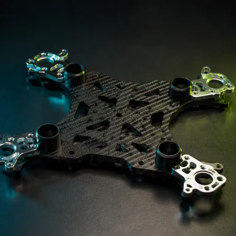
A structural review of a failing UAV programme almost always starts with the question of material and almost always ends somewhere else. The material is usually adequate. What went wrong is geometric: an arm cross-section that was chosen to fit a folding hinge rather than to hold a bending frequency, a centre plate thinned to save mass at the point where four boom loads converge, a payload bracket mounted where the plate is least constrained, and a control loop tuned on a bench that never saw the flexibility of the aircraft it was finally installed in. Two airframes can be built from identical carbon fiber, identical motors and identical propellers and still fly with completely different vibration signatures, because the structure that connects them decides how much of the motor's excitation reaches the sensors.
This guide works through airframe structural design from the perspective of a programme that has to specify, procure and then live with the result. It covers why stiffness rather than strength is normally the governing requirement, how to keep the first bending mode out of the rotor and control bands, how loads actually travel through a multirotor frame, how to size booms and centre plates, and which structural requirements belong in an RFQ so that the delivered airframe matches the one that was analysed. The airframe materials guide covers substrate selection in depth; this article assumes the material is chosen and deals with what the geometry has to do with it.
Stiffness, not strength, is usually the binding constraint
A strength check asks whether the structure survives a load. A stiffness check asks whether the structure moves too much under a load it was always going to survive. On small and medium UAVs the second question governs, and the reason is that the failure mode is rarely fracture. A 5 kg multirotor in a 15 m/s gust will bend its arms by millimetres and return to shape without any permanent damage — that is a pass on strength and a failure on stiffness, because while the arm was bending the IMU was reading the bend as an attitude disturbance, and the flight controller issued a correction to a motion that was not the aircraft rotating at all.
The practical consequence is that a UAV airframe should be designed against a deflection budget at defined load cases rather than against a stress allowables table. Two numbers make that budget usable. The first is static stiffness at the motor mount: the displacement of the mount under a lateral load equal to the maximum thrust the propulsion system can produce, typically expressed as a deflection in millimetres per kilogram of thrust. The second is the first natural frequency of the assembled airframe with representative payload mass installed, which is the number that decides whether the structure behaves as a rigid body from the controller's point of view.
There is a secondary reason stiffness dominates. Structural weight in a UAV is close to a fixed budget, and strength-driven designs tend to convert that budget into material where stress is highest — often a local bracket detail — while stiffness-driven designs put it into section depth and material placement where it raises the frequency of the whole assembly. A frame designed purely against yield ends up with heavy local reinforcements and a low overall frequency. That is the worst of both outcomes on a flying platform.
| Requirement | Strength-driven design | Stiffness-driven design | What it decides in flight |
|---|---|---|---|
| Governing load case | Peak gust or crash load at yield margin | Deflection at maximum continuous thrust | Attitude hold quality in turbulence |
| Where material goes | Local high-stress brackets | Section depth, boom walls, plate skins | Overall first bending frequency |
| Typical failure observed | Delamination or fastener pull-through | Oscillation, sensor bias, payload blur | Whether autopilot tuning holds |
| Mass outcome | Heavy local fixes, low global frequency | Distributed mass, high global frequency | Endurance and stability together |
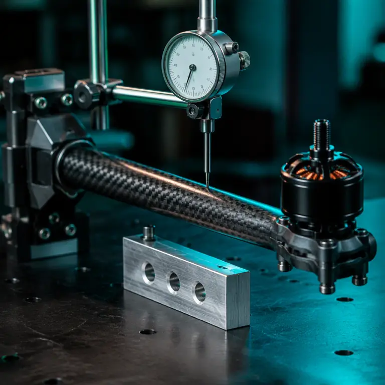 Deflection at the motor mount is the design number
Keeping the first bending mode clear of the rotor band
Every airframe has bending modes, and the lowest one matters most. The first bending mode of a multirotor is typically the symmetric or anti-symmetric flexing of the arms and booms relative to the centre body, and it lands somewhere in the tens of hertz for a small platform and lower for a large one with long, slender booms. The excitation that finds it is the rotor: blade-pass frequency is the motor speed multiplied by the number of blades, and the fundamental rotor line is the shaft speed itself. A propeller spinning at 6,000 rpm produces a 100 Hz shaft line and, for a two-blade propeller, a 200 Hz blade-pass line; a large slow propeller at 2,500 rpm puts those lines at roughly 42 Hz and 83 Hz. Both ranges overlap comfortable structural frequencies, which is exactly the problem.
The design rule is separation, not damping. The first airframe bending mode should sit at least 25 to 30 per cent below the lowest significant rotor line and comfortably above the control loop bandwidth, so that no sustained excitation sits on the peak and no control action drives the structure near it. Getting the mode below the rotor band is normally the right target on a multirotor, because rotor speed rises with payload and with battery voltage, so the excitation moves upward in frequency as the flight progresses while the structural mode stays where it was built. Designing the frame so its first mode is already below the lowest in-flight rotor line means the separation improves rather than degrades as the aircraft works harder.
Two details make this harder than the rule suggests. The first is that the assembled mode is not the bare-frame mode: payload mass, battery mass, gimbal and its isolator all lower the frequency, and a frame measured at 38 Hz on the bench with no payload can easily sit at 26 Hz once a 2 kg sensor is bolted underneath. Structural analysis should always be run with representative masses at their real mounting locations. The second is that the mounting of the flight controller matters as much as the frame frequency; a controller hard-mounted to a plate that is itself near a mode will read amplified motion regardless of how the frame was tuned, which is why the vibration isolation guide treats the isolator and the structure as one problem rather than two.
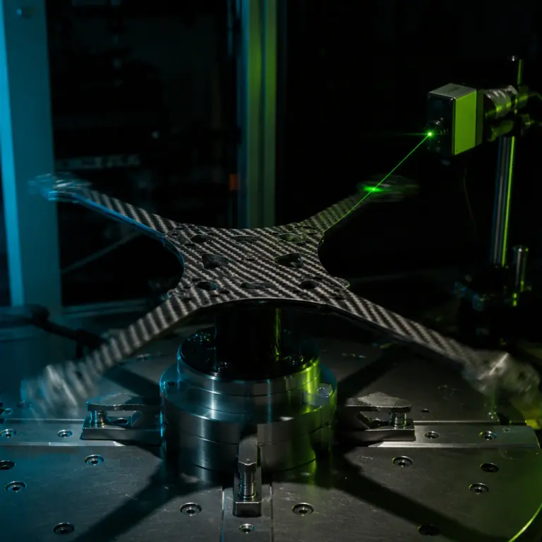 The assembled mode, with payload mass installed, is the one that counts
How loads actually travel through a multirotor frame
Structural design becomes tractable once the load paths are drawn. On a multirotor the dominant path starts at the propeller, which applies thrust and torque at the motor, and torque and bending at the mount. The mount transfers that into the boom or arm as a combination of bending moment, torsion and shear. The arm transfers it into the centre plate at the boom socket, where four arms converge and the moments from opposite arms can either cancel or add depending on the manoeuvre. The centre plate then distributes the result into the battery mass, the avionics and the payload hardpoint. A payload suspended below the plate by a bracket adds a downward force and an inertia couple, and a gimbal adds a lightly damped mass on a compliant interface.
The failure of a load-path review is usually a discontinuity. A boom socket that is bolted through a thin plate concentrates the boom's bending moment into a small number of fastener holes; the plate may pass a global stress check while the local bearing stress at those holes is what actually limits the design. A payload bracket mounted at a point where the plate is only supported by the battery strap has no direct route to the arm reactions, so it moves relative to the motors and the sensor sees that relative motion. Drawing the path from motor to payload explicitly, and asking at each interface whether the load has a direct and stiff route onward, exposes these problems before they become a vibration signature.
A useful test is to ask where the structure would deform if a single arm produced twice its normal thrust. If the answer is a local bracket that has no continuation into the surrounding structure, the load path ends there and the payload will see it. Good airframe design makes each interface a continuation of the previous section rather than a joint that hangs off it, which is why bonded composite construction with continuous fibre paths generally outperforms a bolted assembly of individually strong parts at the same mass.
| Interface | Loads arriving | The structural question to answer |
|---|---|---|
| Motor mount to boom | Thrust, torque, gyroscopic moment | Is the face perpendicular to the thrust axis and stiff in bending? |
| Boom to centre plate | Bending moment, torsion, shear | Is moment distributed over an area or concentrated at fastener holes? |
| Centre plate to payload hardpoint | Inertia couple, downward force | Does the bracket share the arm reactions or hang off the battery bay? |
| Avionics tray to plate | Local vibration, impact | Is the tray constrained in the axis the sensors measure? |
Sizing booms, arms and centre plates
Boom and arm sizing is dominated by bending stiffness, and bending stiffness in a slender member scales with the second moment of area, not with wall thickness alone. Moving material outward from the neutral axis raises stiffness far more efficiently than adding thickness, which is why a larger-diameter tube with a thinner wall almost always beats a smaller, thicker one at equal mass. For a round carbon tube the practical guidance is to hold the wall above the thickness at which local buckling and handling damage become the limiting case, then select the diameter that puts the arm's cantilevered bending frequency where the mode-separation rule requires. On a folding arm the hinge is the weak point regardless of the tube chosen, because a hinge joint is a stiffness discontinuity by construction; a programme that needs both folding and a high first mode should treat the hinge as the design driver and size the surrounding structure around it.
Centre plate sizing is a different problem because it is a plate with several point loads around its perimeter rather than a beam. The plate's job is to keep the boom sockets coplanar and co-angular under load, so the relevant stiffness is out-of-plane bending and local stiffness at each socket, not in-plane tensile strength. A plate that is thin in the region between sockets allows the arm reactions to tilt the sockets relative to one another, which changes the thrust-line geometry in flight and produces a slowly varying trim bias rather than a high-frequency vibration. Local reinforcement around each socket — a bonded boss, a thickened pad, a machined insert — is what carries the concentrated moment into the plate without relying on the plate's own thickness at that point. This is where the manufacturing decisions described in the assembly tooling guide stop being a workshop detail and become a structural requirement, because a socket that is bonded without alignment control is a socket at an unknown angle.
Layup direction deserves the same explicit treatment as geometry on composite frames. Unidirectional fibre carries load along its axis and quasi-isotropic stacks trade peak stiffness for uniformity. A boom wound or laid predominantly in the axial direction maximises bending stiffness for its mass, but it has almost no resistance to the torsional load that motor torque applies, so a purely axial layup can pass a bending check and still wind up under acceleration. The practical stack carries axial plies for bending, a proportion of off-axis plies for torsion and for handling robustness, and additional plies local to the root where bending moment peaks. Where the fibre stops matters as much as where it runs: a ply that is terminated at a socket edge creates a stress concentration that a continuous path would not have.
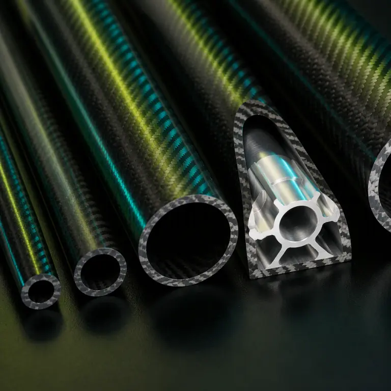 Diameter buys bending stiffness; thickness mostly buys mass
Verifying structure before it flies
Structural verification on a UAV programme does not need a full certification test campaign, but it does need to produce numbers rather than impressions. The minimum useful set is a static stiffness test, a modal identification, and a load-to-limit demonstration on the highest-loaded interface. The static stiffness test applies a known lateral load at each motor mount and measures deflection with a dial indicator or laser displacement sensor: the result is the millimetres-per-kilogram number that the drawing should have specified, and comparing it across the four arms detects asymmetry that a nominal analysis will not predict.
Modal identification for a small airframe is practical without a full test laboratory. An instrumented hammer or a shaker on one arm, an accelerometer at a motor mount and another at the payload hardpoint, and a frequency response measurement give the first bending mode of the assembled structure with payload mass installed. The result to compare against is not an absolute target but the separation margin to the rotor lines across the flight envelope, and the ratio of payload-hardpoint motion to motor-mount motion, which quantifies how much of the arm's bending actually reaches the sensor. A frame whose first mode sits at 60 per cent of the lowest rotor line is a design that will amplify during spool-up and at low battery; a frame whose mode is at 70 per cent of it has margin that improves as the rotor speeds up.
The load demonstration closes the loop on the strength question that stiffness did not answer. Loading the highest-stressed interface — normally the boom socket, the motor mount or the payload attachment — to the limit load defined by the manoeuvre envelope, holding it, and then inspecting for delamination, permanent set and fastener movement produces an auditable record. Acoustic emission monitoring or a simple tap test after the load is released will detect the internal damage that a visual check misses, and the composite NDT guide covers the inspection methods in detail. The output of all three tests is a structural verification report that can be handed to a customer, which is a commercial asset as much as a technical one.
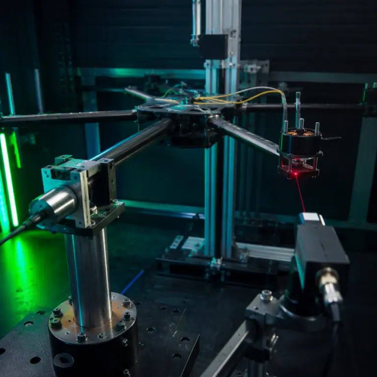 Static stiffness, modal identification and a limit-load hold
Putting structural requirements into the RFQ
Structural performance is invisible in a delivered airframe. A frame with the wrong first mode looks exactly like a correct one, weighs about the same, and passes the same visual inspection. That is precisely why the requirements have to be written into the purchase document rather than discussed and forgotten. The clauses that carry the weight are: the load cases the structure is designed against, stated as thrust and manoeuvre loads at the motor mounts rather than as an abstract safety factor; the stiffness requirement at each motor mount expressed as deflection under a defined load; the minimum first bending mode of the assembled airframe at a stated payload mass, together with the analysis method and the rotor frequency range it must remain separated from; the payload and battery masses and mounting locations used in that analysis, since the result is meaningless without them; the interface tolerances at boom socket, motor mount and payload hardpoint, including flatness and angular relationships; and the verification evidence that will be supplied, which should name the static stiffness test, the modal measurement and the limit-load demonstration with the acceptance criteria for each.
Two commercial clauses belong alongside the technical list. The first is change control on the structure: a supplier who lightens a plate or alters a boom section after verification invalidates the modal result, so the drawing revision that was verified should be named in the contract and any later structural change should require re-verification. The second is the documentation package, because the analysis report, the verification test records and the as-built layup schedule are what allow the buyer to maintain the aircraft and re-qualify a replacement part years later. A programme that cannot answer what the first mode of its own airframe is has no basis for deciding whether a proposed replacement boom is acceptable, and the spares and lifecycle planning guide covers why that gap becomes expensive over a fleet's life.
The bottom line: an airframe is a stiffness structure with a strength obligation, not the other way round. Set a deflection budget at the motor mounts, keep the first bending mode clear of the rotor band with the real payload installed, draw the load path from propeller to payload and make every interface a continuation rather than a bracket, size booms by diameter before thickness, and write the modal and stiffness numbers into the contract with the evidence that will prove them. EMS Drone builds airframes and structural subsystems to specified stiffness and modal targets — datum-controlled sockets, documented layups, machined inserts and the verification records that go with them. Send us your mission profile, payload and mass budget, and the interface dimensions you have already fixed, and we will return the structural requirement set, the analysis assumptions and the verification plan that holds the design point.
Explore Airframes Back to Blog
Continue Reading
Airframe Materials
Carbon fiber, aluminium and G10 compared for UAV structures.
Vibration Isolation
Mounts, transmissibility and the root-2 rule for payloads.
Composite NDT
Detecting delamination and voids in carbon fiber airframes.
Multirotor vs Fixed-Wing
Matching the airframe configuration to the mission.