
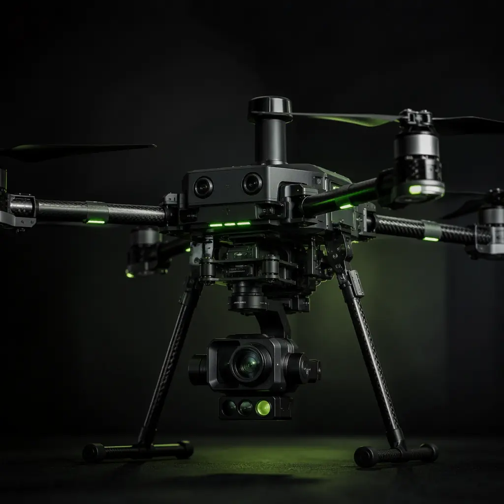
Most UAV procurement conversations start with flight time, range and payload capacity, the three numbers that fit on a datasheet. But specifications at the airframe level tell you almost nothing about whether a particular sensor, gimbal or release mechanism will actually work on your platform. A 5 kg payload capacity does not mean you can hang 5 kg of any shape, at any vibration frequency, drawing any current profile, and expect the system to perform. Payload integration is the discipline of understanding what sits between the mounting rail and the mission output. And it is the most frequently underestimated phase of industrial UAV development.
The integration challenge spans three domains that must be solved simultaneously. The electrical domain covers power delivery, data interfaces and electromagnetic compatibility. The mechanical domain covers center of gravity, vibration isolation and structural mounting. The operational domain covers the workflow from pre-flight calibration through in-flight data acquisition to post-flight processing. A gimbal that delivers silky-smooth 4K footage on the bench but introduces a 2 kHz vibration harmonic into the flight controller's IMU at 60% throttle is an integration failure, not a component failure.
This article approaches payload integration from the perspective of a system integrator who needs to make component-level decisions. It assumes you have already settled the foundational architecture questions covered in the UAV supply chain layers framework and are now moving into subsystem selection. The guidance applies whether you are building a single prototype or scaling to a production run of 50 units.
Start with the mission, not the mounting pattern
The most common mistake in payload selection is starting with a sensor or gimbal that looks impressive and then trying to make the airframe accommodate it. The correct sequence reverses this: define the mission output first, then derive the sensor requirements, then select the payload components that deliver those requirements within the platform's physical and electrical constraints.
For an industrial inspection mission targeting power line corridors, the mission output might be: geotagged thermal imagery at 640 × 512 resolution with ≤5 cm GSD (ground sample distance) from a 30-meter standoff, captured at 2 frames per second with GPS-tagged metadata. This output definition immediately constrains the sensor selection: you need a radiometric thermal camera with a specific lens field of view, a GNSS receiver with ≤2 meter position accuracy, and an onboard storage or downlink system that can handle approximately 240 MB per flight hour. A generic "thermal camera for drones" search will return hundreds of options; a mission-derived specification narrows the field to perhaps three.
For a precision agriculture spraying mission, the payload requirement is fundamentally different: a liquid tank with 10–16 liter capacity, a spray pump delivering 2–4 L/min at 0.2–0.4 MPa, nozzles producing 100–300 μm droplets for drift control, and a flow control system that adjusts output based on ground speed from the flight controller's telemetry stream. The spray system is not an afterthought bolted to a generic airframe. It is the primary payload, and the airframe's center of gravity, vibration modes and electrical budget must be designed around it. The component priorities for low-altitude economy UAVs article explains why the payload-first design philosophy applies across civil UAV applications.
 Concept illustration
Electrical integration: power, data and noise management
Payload electrical integration is where most field failures originate. The issues are not theoretical, they show up as intermittent gimbal resets, corrupted telemetry packets, and ground control station freezes that occur only at specific throttle settings or distances. Solving them requires understanding three interconnected subsystems.
Power delivery. A 3-axis gimbal with a full-frame camera payload typically draws 15–30 W peak, with inrush currents during motor startup that can reach 3× the steady-state draw. A LiDAR scanner like the Livox Mid-40 draws approximately 10 W continuous, but its laser diode pulsing creates microsecond-scale current spikes that couple into the power rail. The BEC (battery eliminator circuit) or power distribution board must be sized not just for the average draw but for the peak transients, and isolated from the flight controller and receiver power rails. A common configuration uses a dedicated 12V or 5V BEC with ≥3A headroom above the payload's rated maximum, a low-ESR electrolytic capacitor (470–1000 μF) at the payload connector to absorb transients, and a separate ground return path to prevent payload return currents from modulating the flight controller's analog ground reference.
Data interfaces. Modern payloads communicate over UART, CAN bus, Ethernet or USB 3.0. The interface choice is not arbitrary, it determines cable weight, connector reliability under vibration, and susceptibility to electromagnetic interference. A gimbal using SBUS or CRSF for control and UART for telemetry adds minimal cable weight but limits data throughput. A multi-spectral camera streaming 5-band imagery at 2 Hz over Ethernet delivers rich data but requires a heavier cable, a managed switch on the airframe, and careful attention to the connector's locking mechanism. An RJ45 connector without a locking tab will vibrate loose within the first 10 flight hours. For CAN bus payloads, the timing parameters and bus loading analysis covered in the flight controller and ESC matching guide apply directly: a payload node that transmits at 500 kbps on a bus already carrying 15 ESC telemetry nodes at 1 Mbps changes the bus timing margin.
Electromagnetic compatibility. Payload electronics generate electromagnetic interference that couples into GNSS antennas, telemetry radios and the flight controller's magnetometer. A gimbal with three brushless motors switching at 16–32 kHz PWM creates broadband noise from 30 MHz to 1 GHz. The mitigation strategy starts with physical separation, GNSS antenna mounted at least 20 cm from gimbal motors, with a ground plane between them, and includes ferrite chokes on all payload power and data cables, twisted-pair wiring for differential signals, and shielding on the gimbal controller enclosure. Pre-flight validation should include a spectrum analyzer sweep from 100 MHz to 6 GHz at the GNSS and telemetry antenna positions with the payload operating at full power. For the RF environment more broadly, the UAV RF communication systems guide covers frequency coordination and interference management across the full drone radio stack.
Mechanical integration: weight, CG and vibration
The mechanical integration of a payload is governed by three numbers: mass, moment arm and natural frequency. Getting any of them wrong produces a drone that flies, but flies poorly, consuming excess power, delivering degraded sensor data, and fatiguing airframe components at an accelerated rate.
Center of gravity. The payload's CG should sit as close as possible to the aircraft's thrust centerline: typically directly below the geometric center of the motor plane for a multirotor. A 1.5 kg gimbal mounted 15 cm forward of the CG creates a pitch-down moment that the flight controller must continuously compensate for. This constant compensation burns additional power (approximately 8–15% more current draw on the front motors in a quadcopter configuration), reduces maximum thrust margin for maneuvering, and accelerates wear on the front ESCs and motors. For fixed-wing or VTOL platforms, the CG shift affects stall characteristics and transition behavior. A forward CG makes the aircraft more stable but increases stall speed, while an aft CG reduces stability margin.
The UAV airframe materials guide is directly relevant here because the airframe's structural stiffness determines how much CG shift the platform can tolerate before the flight controller's attitude loop becomes unstable. A carbon fiber airframe with a natural frequency above 80 Hz can accommodate larger CG offsets than an aluminum frame resonating at 45 Hz, simply because the control loop sees the mechanical response sooner and with less phase lag.
Vibration isolation. The vibration environment at the payload mounting point is dominated by motor/propeller harmonics: typically 80–200 Hz for large multirotors with 18–28 inch propellers spinning at 3,000–5,000 RPM. A gimbal's IMU-based stabilization can compensate for low-frequency attitude changes (below approximately 10 Hz) but cannot reject high-frequency vibration that couples directly into the camera sensor, producing the rolling-shutter jello effect familiar to anyone who has mounted a camera without proper isolation.
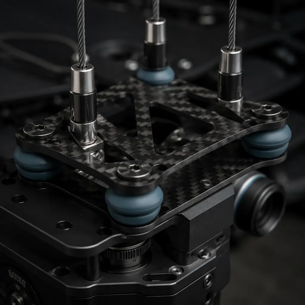
The isolation solution is a tuned dampener system with a natural frequency well below the first motor harmonic. For a platform with a first motor harmonic at 80 Hz (4,800 RPM), the isolator's natural frequency should be below 20 Hz, ideally in the 8–12 Hz range. This requires selecting dampener durometer and geometry to achieve approximately 1.5–2.5 mm of static compression under the payload's mass. Wire rope isolators, silicone gel dampeners and Sorbothane pads each have different stiffness-to-damping ratios; wire rope isolators offer the broadest frequency attenuation but add approximately 50–80 grams of weight per mounting point compared to silicone alternatives.
 Concept illustration
Payload categories: gimbals, sensors and release mechanisms
Most industrial UAV payloads fall into three categories, each with distinct integration requirements. Understanding which category your mission needs, and which combinations are feasible on a single platform, is the first integration-level decision.
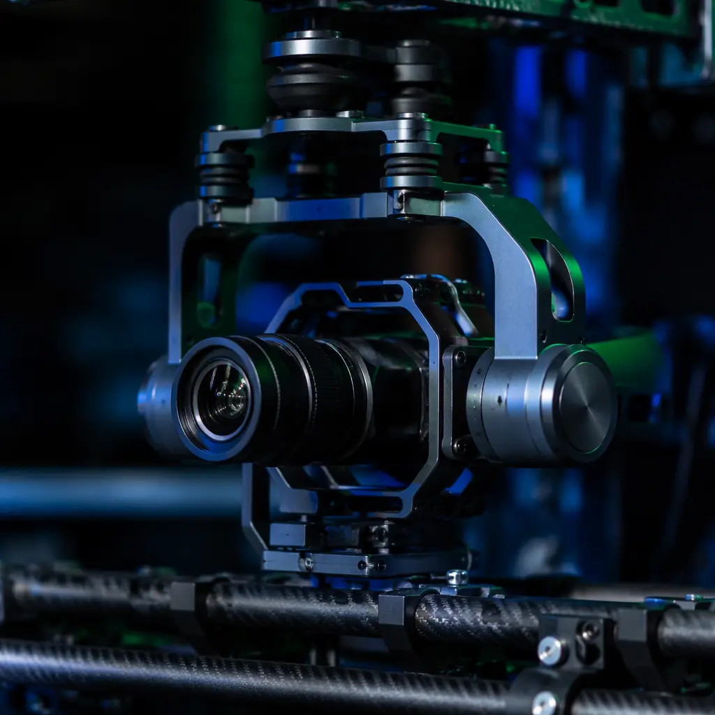
Stabilized gimbals. A 3-axis gimbal carrying an EO/IR camera, a multi-spectral sensor or a LiDAR unit is the most common payload configuration for inspection, mapping and surveillance missions. The gimbal itself is a precision electromechanical system with its own IMU, motor drivers and control loop running at 500–1000 Hz. Key selection criteria include: angular stabilization accuracy (≤0.01° for long-range surveillance, ≤0.05° for mapping), gimbal weight as a fraction of total payload capacity (ideally ≤60%, a 1 kg gimbal carrying a 400 g camera wastes capacity on stabilization hardware), and the gimbal's control interface protocol. A gimbal that accepts MAVLink gimbal commands directly from the flight controller is easier to integrate than one requiring a separate ground control channel and operator joystick.
Fixed-mount sensors. Not every sensor needs stabilization. A nadir-mounted LiDAR scanner, a downward-facing multispectral camera array, or an atmospheric sampling probe can be rigidly mounted if the aircraft's attitude during data collection is stable enough. For mapping missions using RTK GNSS with centimeter-level accuracy, the fixed-mount approach eliminates the angular uncertainty introduced by gimbal encoder resolution. The sensor's position and orientation are determined entirely by the aircraft's known attitude from the flight controller's EKF (Extended Kalman Filter) at each geotag event. The trade-off is that fixed-mount sensors are sensitive to aircraft roll and pitch during turns and wind gusts, which can create gaps in the data swath that require post-processing interpolation.
Release and actuation mechanisms. Delivery drones, agricultural sprayers and search-and-rescue platforms need payloads that actively interact with the environment, dropping a package, spraying a liquid, releasing a life ring. These mechanisms introduce unique integration challenges: the release event itself creates a sudden CG shift, the actuation motor or solenoid draws a current spike that can brown-out the flight controller if not on an isolated power rail, and the mechanism's moving parts must be tested across the full temperature and humidity range of the mission profile. A delivery winch rated for 5 kg that jams at -10°C because the lubricant viscosity doubled is an integration oversight, not a component defect.
For programs evaluating whether to develop a custom payload integration or purchase an off-the-shelf solution, the build-versus-buy framework in the UAV component sourcing strategy article provides a structured decision process.
Payload integration testing: what to validate before first flight
The integration testing sequence should catch problems on the bench, not in the air. A structured test plan with five gates prevents the most common failure modes from reaching flight testing.
Gate 1: Bench power test. Power the complete system, flight controller, ESCs, motors (props off), telemetry radios and payload, from a bench supply with current logging. Run the payload through its full operational sequence: gimbal initialization, full-range pan/tilt sweeps, camera recording start/stop, and any actuation cycles. Record the minimum, average and peak current draw. Verify that the power system's rated capacity exceeds the measured peak by at least 25%. Measure voltage at the payload connector under full load, sag below the payload's minimum rated voltage (typically 11V for a 12V nominal system) indicates undersized wiring or connectors.
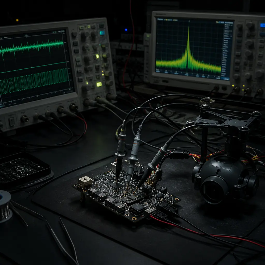
Gate 2: EMI sweep. With the payload operating at maximum electrical activity (gimbal motors tracking, camera streaming, data link transmitting), use a spectrum analyzer or an SDR dongle with an appropriate antenna to scan the GNSS L1 (1575.42 MHz), L2 (1227.60 MHz) and telemetry bands (433 MHz, 868/915 MHz, 2.4 GHz). Any noise floor increase above 6 dB at the GNSS frequencies with the payload on versus off requires mitigation before flight. A 6 dB noise rise can reduce the GNSS receiver's carrier-to-noise ratio enough to drop satellites in marginal reception conditions.
Gate 3: Vibration survey. Mount an accelerometer at the payload mounting point and run the motors through a throttle sweep from idle to 80% with propellers installed (aircraft secured to a test stand). Identify the dominant vibration frequencies and amplitudes. Compare these against the payload manufacturer's vibration tolerance specification. If the measured vibration exceeds the payload's limit at any throttle setting, adjust the isolator stiffness or add mass to the isolation stage to shift the resonant frequency away from the motor harmonics.
Gate 4: Data path validation. Exercise every data path from the payload to its destination. Whether that is onboard storage, a telemetry downlink or both. For a gimbal: confirm that gimbal attitude telemetry appears in the ground control station at the expected update rate. For a camera: record 30 minutes of continuous video to onboard storage while the aircraft systems are running and verify zero dropped frames. For a spray system: log the flow rate sensor telemetry alongside GPS position and confirm that the data records align in time to within 100 ms, the post-processing software that generates an as-applied map depends on this synchronization.
Gate 5: Fail-safe behavior. Simulate a payload power loss by disconnecting the payload BEC while the system is running. Verify that the flight controller continues normal operation without resetting, that the ground control station displays a clear "payload offline" indication, and that the pilot can continue flying the aircraft on the primary control link. A payload failure should never cascade into a flight control failure. This is the fundamental architectural requirement, and it is enforced by electrical isolation, not by hoping the payload never fails.
 Concept illustration
Mission-specific payload configurations
Different mission profiles demand fundamentally different payload architectures. The table below maps four common industrial UAV missions to their typical payload configurations and the integration challenges each presents.
Infrastructure inspection. A typical inspection platform carries a dual-sensor gimbal, a 640 × 512 radiometric thermal camera alongside a 20 MP visible-light camera with 20× optical zoom, plus a laser rangefinder for accurate standoff distance measurement. The gimbal must hold position to within 0.01° while the aircraft hovers in gusting wind. The data path must support simultaneous thermal and visible video streams, each at 30 fps, with frame-accurate timestamps for correlation during post-flight analysis. The integration challenge is managing the combined 40–50 W power draw from the gimbal and sensors without introducing noise into the flight controller's power rail.
Mapping and survey. A mapping platform typically carries a nadir-mounted full-frame camera (Sony A7R series or Phase One industrial), a multi-band GNSS receiver with RTK corrections for cm-level positioning, and optionally a lightweight LiDAR scanner for terrain modeling under vegetation canopy. The payload is often rigid-mounted, no gimbal, because the photogrammetry processing pipeline needs the precise angular relationship between the camera and the GNSS antenna phase center. The integration challenge is maintaining this geometric rigidity across temperature changes: a 20°C thermal swing can shift the camera's optical axis relative to the GNSS antenna by 0.1–0.3 mm through aluminum bracket expansion, translating to several centimeters of positional error at 120 m AGL.
Precision agriculture. The primary payload is a liquid spray system: tank, pump, boom with nozzles, and flow control electronics. The payload mass dominates the aircraft. A 16-liter tank with full spray system can weigh 18–20 kg, representing 70–80% of the aircraft's maximum takeoff weight. The CG shifts continuously during flight as the tank empties. The integration challenge is designing the tank geometry and mounting position so that the CG shift over the full range from full to empty stays within the flight controller's trim authority: typically requiring the tank's centroid to be positioned within 5 cm of the aircraft CG.
Logistics and delivery. A delivery drone carries a package in a release mechanism: typically a servo-actuated hook, a motorized winch for tethered delivery, or a spring-loaded cargo bay. The payload is not a precision instrument; it is a structural element that must survive repeated mechanical cycling. The integration challenge is ensuring that the release mechanism does not inadvertently actuate from RF interference, vibration or software fault, and that the aircraft remains controllable through the sudden 2–5 kg CG shift that occurs at the moment of release. For the powertrain considerations specific to heavy-lift platforms, the UAV powertrain matching guide covers the motor, ESC and propeller sizing calculations.
Explore payload integration capabilities Back to Blog
Continue Reading
UAV RF Communication Systems
Data links are the payload's connection to the ground, choose the right one.
Airframe Materials Guide
Structural stiffness directly affects payload vibration isolation performance.
UAV Powertrain Matching
The thrust budget that determines how much payload you can carry.
FC & ESC Matching
CAN bus loading analysis applies to payload nodes on the same bus.
Build vs Buy Sourcing
Whether to develop custom payload integration or buy off-the-shelf.