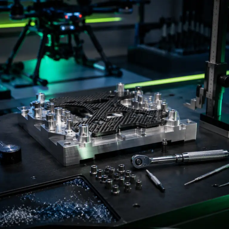
The first aircraft is easy. The twentieth is where a UAV programme finds out whether it has a manufacturing process or a workshop habit. The failure pattern is consistent and almost never a component problem: the motor mount holes on airframe eleven sit 0.4 mm out of position, so the arm bolts load unevenly and the vibration signature changes; the flight controller tray was bonded without a jig and the board is not parallel to the thrust line, so the autopilot trims against a mechanical bias on every flight; a fastener was torqued until it felt tight, and a year later a seized bolt shears the insert out of a composite plate during servicing. Each of these costs a few hundred dollars of rework on one aircraft and an unquantifiable amount of credibility when a customer discovers that two units of the same model do not behave the same way.
Tooling is the discipline that removes that variation. It is also, in most UAV supply chains, the least specified part of a build: buyers scrutinise component datasheets and ignore the jigs, the torque schedule and the calibration records that decide whether those components actually perform as specified once installed. This guide works through the four tooling families that matter on a UAV airframe line — drill and locating tooling, bond and alignment tooling, torque and fastener control, and calibration and metrology — and then turns each into the RFQ language that makes it enforceable. The airframe materials guide covers the substrates these tools work against, and the connectors and power distribution guide covers the harness side of the same build.
Why tooling is a procurement topic, not a workshop topic
The commercial argument for tooling is that it converts an uncontrolled process into a measurable one. Without a drill jig, hole position tolerance on a hand-drilled carbon fiber plate realistically runs to ±0.5 mm or worse, and it drifts between operators and between shifts. With a hardened bushings jig, the same operation holds ±0.1 mm and the position is repeatable by anyone on the line, including a new hire on their first week. That is the difference between a build that can be scaled and a build that depends on one experienced technician being present.
The second argument is serviceability. A tooling set defined at design time is what makes a replacement arm, a spare centre plate or a field-replaced motor mount interchangeable a year later. If the interface was never controlled, no two aircraft are identical and every spares order becomes a bespoke engineering job — a cost that shows up in the spares and lifecycle budget long after the tooling was skipped to save a few thousand dollars. A programme that intends to build more than a handful of airframes should treat the tooling set as a deliverable of the same standing as the drawings, because the drawings alone do not produce a repeatable part. The spares and lifecycle planning guide covers how interchangeability feeds the total cost of ownership.
| Process step | No tooling (freehand / by eye) | Jigged and controlled | What it protects |
|---|---|---|---|
| Motor mount hole pattern | ±0.5 mm position, bolt-hole mismatch, uneven preload | ±0.1 mm via drill bushing plate | Thrust-line alignment, vibration signature |
| Flight controller tray bonding | Tilt of 0.5-2°, autopilot trims against bias | <0.2° via bond jig with shim control | Sensor frame alignment, hover stability |
| Boom clamp torque | 20-60% scatter across operators | ±10% with calibrated wrench and schedule | Joint preload, fatigue life, boom rigidity |
| Centre plate flatness after cure | Warp of 0.3-1 mm, arm mounts not coplanar | <0.15 mm on a cure plate / caul | Arm coplanarity, airframe squareness |
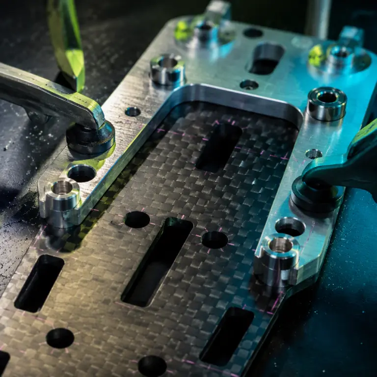 Hardened bushings set the hole pattern, not the operator
The four tooling families on a UAV airframe line
Locating tooling is the first family and the one that most directly fixes geometric repeatability. It begins with a datum strategy: a small number of features — usually the centre plate mounting holes and one edge — that every subsequent operation references, so that tolerance stacks do not accumulate independently down each branch of the build. Tooling built on a shared datum is why holes for a boom clamp, an arm mount and a payload hardpoint end up in a coherent relationship instead of three separately reasonable but mutually inconsistent positions. The practical hardware is a drill bushing plate, a set of dowel pins and a fixture base with the datum marked and protected, because a datum that gets nicked or worn stops being a datum.
Bond and alignment tooling is the second family and the least visible, because a bonded joint hides its own geometry. Composite airframes are commonly assembled with structural adhesive rather than fasteners at the plate and shell interfaces, and a bond jig does three things at once: it holds the two parts in the correct relative position while the adhesive cures, it applies the bond-line thickness the design assumed, and it prevents the shrinkage and thermal movement of cure from pulling the assembly out of square. Shore hardness of the jig's contact pads matters, because a rigid steel pad clamping a thin laminate can dent or crush the very surface being bonded. Where an angular relationship is critical — flight controller mounting plane relative to the motor mounts is the classic case — the jig should control the angle directly with a machined face or a shim pack rather than relying on the parts being individually accurate.
Torque and fastener control is the third family, and the one with the widest scatter when it is left informal. A bolted joint in a composite structure has a narrow window of correct preload: too little and the joint frets and loosens under vibration, too much and the laminate crushes or the insert pulls through. Studies of hand-torqued fasteners routinely find a spread of 20 to 60 per cent between operators using the same wrench, which is why a calibrated torque wrench with a written schedule — per fastener size, per substrate, per location — is a specification and not a convenience. Thread-locking strategy belongs in the same schedule: a chemical thread locker, a nylon-insert nut and a safety wire each behave differently under vibration and each has a temperature and serviceability implication. The vibration isolation guide covers what happens to a joint when preload is wrong.
Calibration and metrology is the fourth family and the one that keeps the other three honest. Jigs wear, bushings open up, torque wrenches drift and cure plates lose flatness. A tooling programme needs a defined calibration interval for every measuring and torque instrument, a wear inspection interval for every locating feature, and a first-article inspection that measures the finished assembly against the drawing rather than trusting that the tooling produced a correct part. The useful number to track is capability: measure the same feature across consecutive units and compare the spread to the drawing tolerance. If the process spread approaches the tolerance band, the tooling is a quality risk even when every individual part passes.
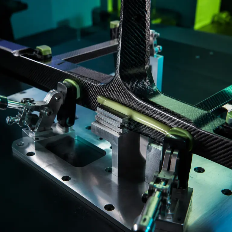 A bond jig holds geometry while the adhesive cures
The motor mount interface: a specification, not a workshop decision
The motor mount is where the tooling argument becomes concrete, because it is the point at which three separately manufactured parts — the arm or boom, the mount plate and the motor — have to agree on geometry that no one of them defines alone. The dimensions that need to be nailed down on the drawing are the hole pattern and its pitch, the hole diameter relative to the fastener (a clearance hole, a close-fit hole or a threaded insert each demand different tolerances), the mounting face flatness, the perpendicularity of that face to the thrust axis, and the height of the mount above the arm to clear the propeller at the intended blade pitch.
The consequences of leaving this to the workshop are not subtle. Uneven bolt-hole positions mean the mount sits on a biased contact pattern, so one side of the plate carries more preload and the joint fatigues at the loaded bolts first. A mounting face that is not perpendicular to the thrust axis tilts the motor, which costs thrust and generates a vibratory force at blade-pass frequency that the flight controller has to fight. An interface height that was set by eye fouls the propeller under flex or at high collective pitch, and the contact is discovered as a chipped blade. None of these are visible on a component datasheet, and all of them are fixed by a jigged interface defined on the drawing.
Two further details belong in the same specification. The first is the fastener standard: a common metric pattern with a stated grade and coating makes field service possible anywhere, whereas a proprietary pattern makes every replacement a shipment. The second is the material and finish of the mount itself, because a mount that is stiff enough to transmit vibration but soft enough to deform under an over-torqued fastener simply relocates the problem into the airframe. The motor KV selection guide covers the propulsion side of the same interface, and the propeller balancing and vibration analysis guide covers what an out-of-alignment mount looks like in the vibration spectrum.
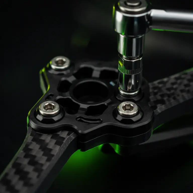 Preload, not tightness, decides joint life
Torque control and fastener retention in practice
A torque schedule is a table, and building one is straightforward once the joint is understood. For each fastener position it states the thread size and pitch, the substrate being clamped, the target torque and the tolerance band, the tightening sequence where several fasteners share a joint, and the retention method. The target torque itself derives from the preload the joint needs, which depends on the bolt's tensile area and the compressive strength of the material under the washer — a composite laminate will accept far less clamp load than a machined aluminium boss before it crushes, so the same bolt size can require very different targets in the two locations.
Sequence matters as much as value when a joint uses multiple fasteners. Tightening a four-bolt pattern fully on one bolt before moving to the next tilts the plate and leaves the first fastener under-loaded once its neighbours compress the interface; a staged pattern — snug all, then step up in two or three passes to final torque — distributes the load evenly and is the reason a schedule names an order and not just a number. Where a joint is likely to be serviced in the field, the schedule should also record whether the fastener is a torque-to-yield type that must be replaced on removal, because reusing one is a silent reduction in margin.
Retention is the second half of the problem, and vibration is the reason. A fastener that is correctly preloaded rarely loosens, because preload is what resists the relative motion that would back it out; a fastener that loosens almost always started under-preloaded or lost preload because the material beneath it relaxed. Beyond correct torque, the practical options are a chemical thread locker for a permanent joint, a nylon-insert or all-metal prevailing-torque nut for a serviceable one, and safety wire or a folded tab washer for a joint where failure is unacceptable and inspection access is possible. Each adds a step to the assembly instruction and an item to the first-article check, and each should be named in the schedule rather than chosen on the line.
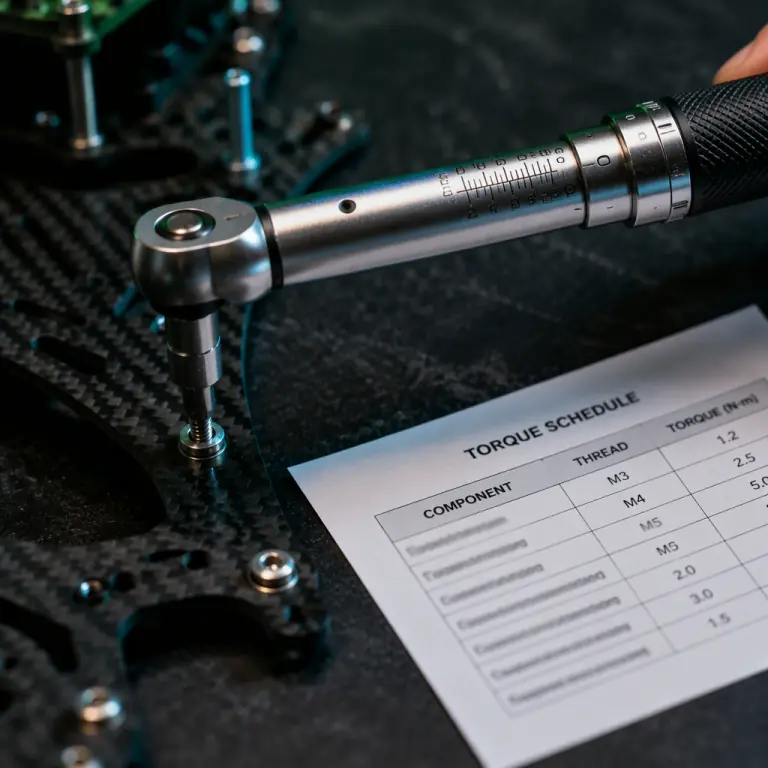 Written schedule, calibrated instrument
Calibration, wear management and first-article inspection
Tooling degrades, and the degradation is invisible until parts start failing a check. A drill bushing that has opened by a tenth of a millimetre still accepts the drill and still looks correct, but it no longer produces the hole the drawing calls for. A bond jig whose locating pads have compressed by repeated use no longer sets the bond-line thickness the design assumed. The management system that catches this is unglamorous and effective: a tooling register that lists every jig, fixture, gauge and torque instrument with its owner, its calibration or wear-check interval, and its last verified date; and a rule that a tool past its interval is not used.
First-article inspection is where tooling and quality control meet, and its purpose is to prove the process rather than the part. The first unit out of a new jig is measured comprehensively against the drawing — hole positions, flatness, angular relationships, fastener torque records, bond-line thickness if it is measurable — and the measurements are recorded as the baseline for the process. Every subsequent unit is then checked against a reduced set of critical dimensions, on the logic that if the tooling is unchanged and within its wear interval, the parts it produces will match the first article. When a critical dimension begins to drift outside its control band, that is the trigger for a tooling inspection rather than a stream of rework. The pre-shipment inspection guide covers the sampling approach applied to finished units, and the electronics manufacturing quality guide covers the equivalent process controls on the avionics side of the same build.
| Tooling item | Degradation mode | Check interval | Failure if missed |
|---|---|---|---|
| Drill bushing plate | Bushing bore wear, plate distortion | Per 200 holes or 3 months | Hole position drift, bolt-hole mismatch |
| Dowel pins / datum features | Fretting, rounding, nicks | Monthly visual, annual measure | Tolerance stack shifts across the whole build |
| Bond / alignment jig | Pad compression, face wear, distortion from cure heat | Per 50 assemblies or 3 months | Angle and bond-line drift, out-of-square frame |
| Torque wrench | Spring fatigue, calibration drift | Annual calibration, monthly verification | Preload scatter, crushed laminate or loose joint |
| Cure plate / caul | Loss of flatness, resin build-up | Per 100 cures, measure flatness | Warped centre plate, non-coplanar arm mounts |
Specifying tooling and build control in the RFQ
Tooling belongs in the procurement document because it is the mechanism by which the supplier promises a repeatable product rather than a good first sample. The clauses that carry the weight are: the datum strategy and the controlled interfaces, with the datum features named and their tolerances stated; the tooling set that will be used for locating, bonding and alignment, with the tolerance each tool holds; the torque schedule, including target values, tolerance bands, tightening sequences and the retention method per joint; the calibration and wear-management regime, with intervals and the records that will be provided; the first-article inspection plan, listing the dimensions measured and the acceptance criteria; the process capability expectation, expressed as a requirement that the process spread sits inside a stated fraction of the tolerance band; and the tooling ownership and transfer arrangement, since a buyer who paid for the tooling should know whether it stays with the supplier or moves with the programme.
The screening questions that separate a real manufacturing process from a workshop are short. Ask the supplier to send the torque schedule for the airframe, not to describe their torque practice. Ask what they measure on the first article and what they measure on unit fifty. Ask how often the drill bushings and the bond jigs are inspected, and what happens when a check fails. Ask whether a replacement arm purchased in eighteen months will bolt to the same hole pattern without a new drawing. A supplier who answers those from a register and a procedure is running a process; a supplier who answers from memory is running a workshop with good intentions. The supplier evaluation checklist places those questions inside a broader screening framework, and the RFP writing guide turns them into enforceable contract language.
The bottom line: components define what an aircraft is capable of, and tooling decides whether the twentieth aircraft is the same as the first. Control the datum before the first hole is drilled, jig the bond lines that set geometry, write the torque schedule and calibrate the wrench that applies it, and keep every jig on a register with a real inspection interval. EMS Drone supports airframe and subsystem builds with the tooling, controlled interfaces and documentation that make a programme repeatable — datum-controlled locating and bond tooling, torque schedules, calibration registers and first-article inspection plans, delivered alongside the components they hold. Send us your drawings, your target build rate and the dimensions your build has drifted on before, and we will return the tooling set, the controlled interface list and the first-article inspection plan.
Explore Airframes Back to Blog
Continue Reading
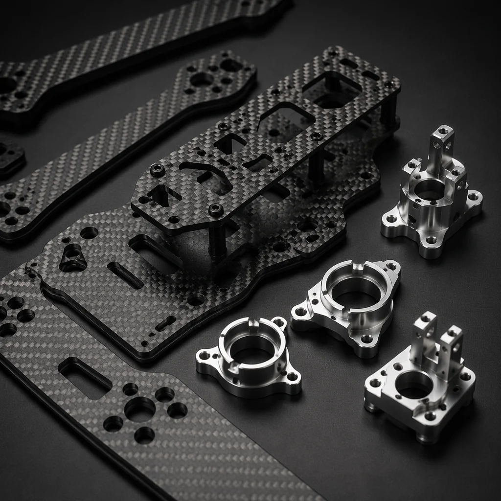
Airframe Materials
Carbon fiber, aluminium and G10 compared for UAV structures.
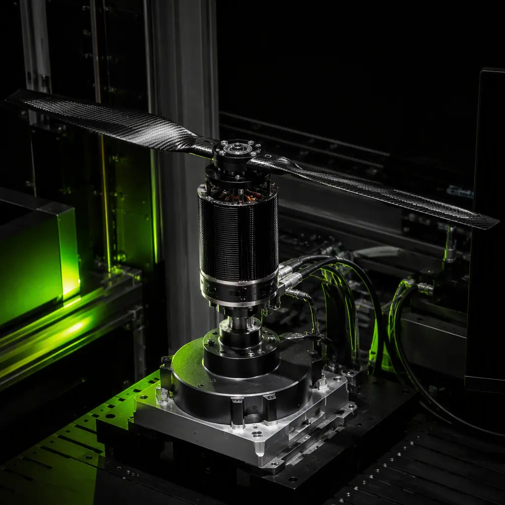
Propulsion Testing
Thrust stands, thermal endurance and how a build is validated.
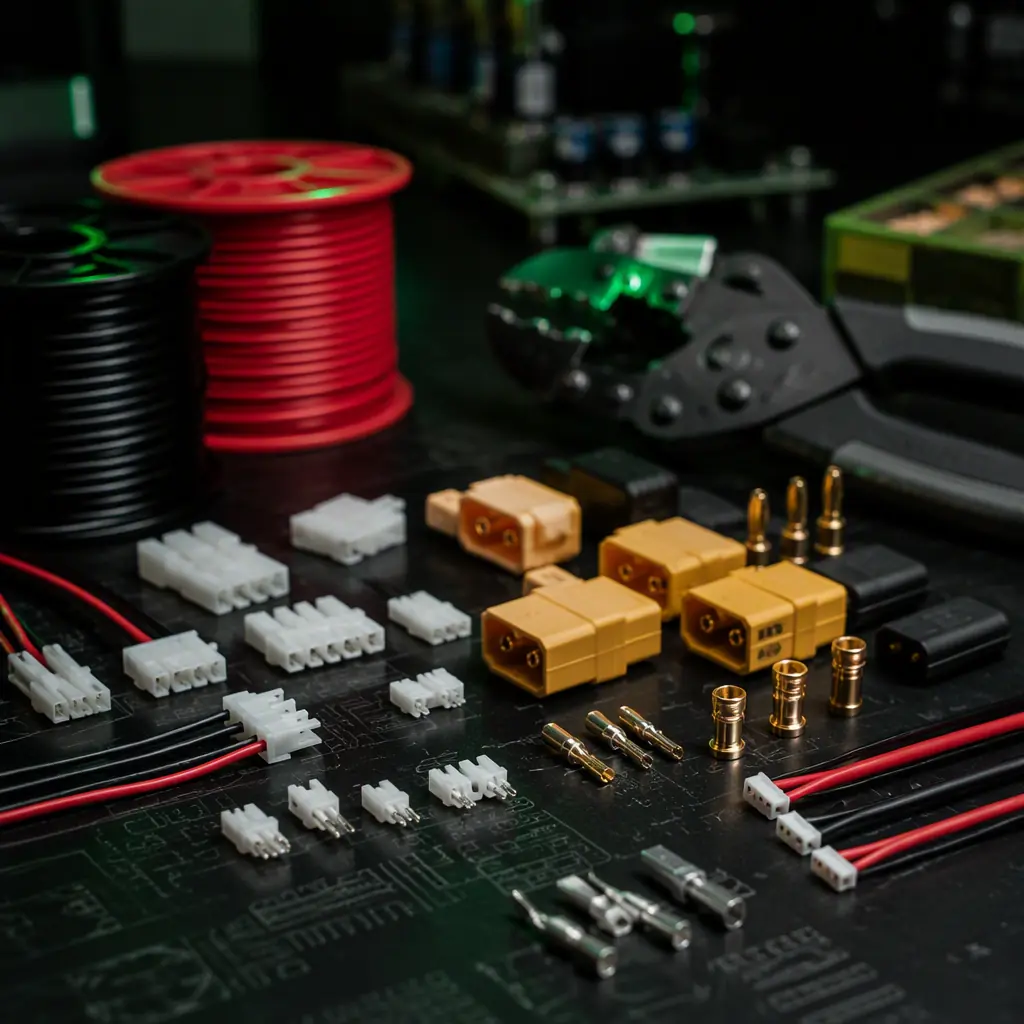
Connectors & Harness
Harness architecture, connectors and power distribution rules.

Manufacturing Quality
IPC-A-610, J-STD-001 and process control on UAV electronics.