
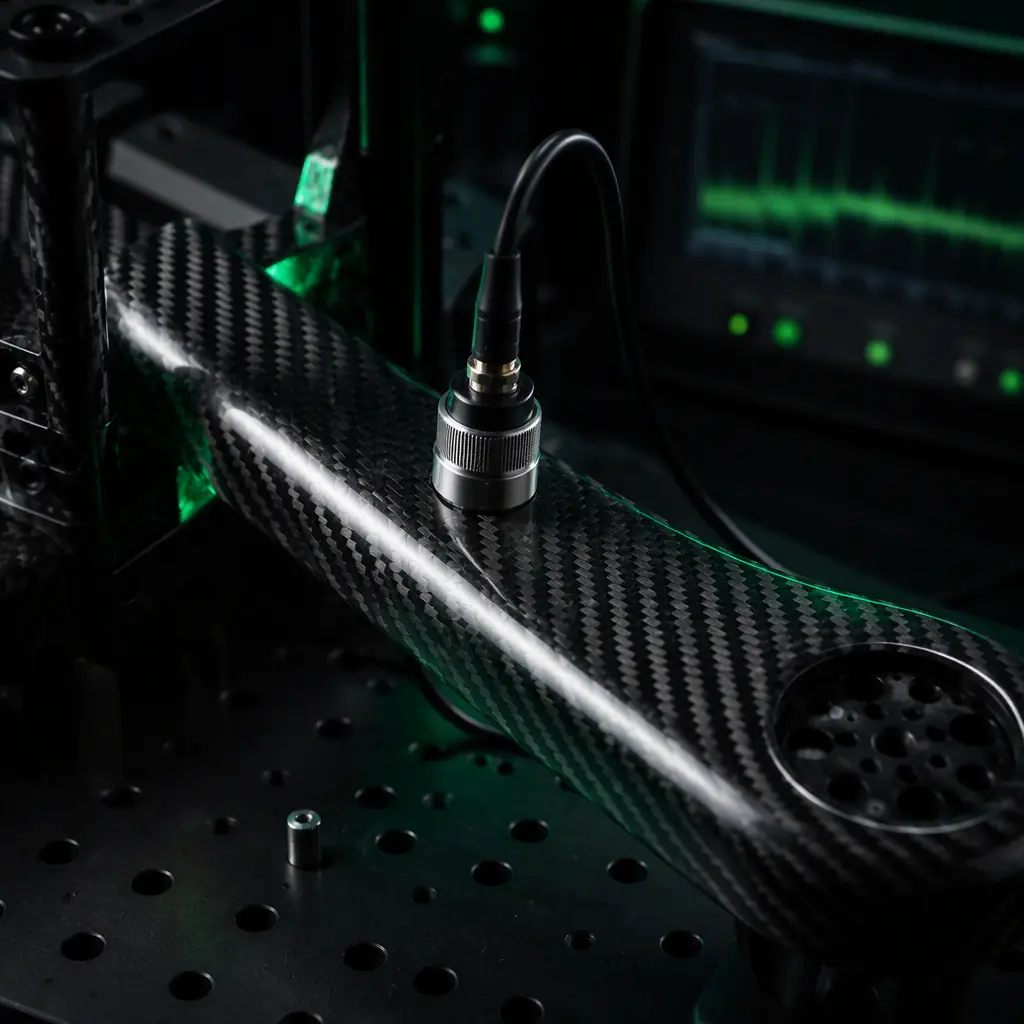
Composite structures are the material of choice for UAV airframes because they deliver the stiffness-to-weight ratio that endurance demands, the airframe materials guide compares carbon fiber, aluminum and G10 in detail. But the same laminated structure that makes carbon fiber strong also makes it hard to inspect: damage is internal, invisible from the surface, and does not announce itself with a bent part the way a metal component does. This guide is written for the maintenance and procurement teams who own that problem.
Why composite airframes need NDT: the defect classes that matter
Every composite airframe accumulates damage in service, and the damage types that threaten flight safety share one property: they are internal. The defect classes that matter for UAV structures:
- Delamination. Separation between adjacent plies of the laminate, the most common fatigue and impact damage mode in thin skins. A 10 mm delamination in a loaded wing spar region can reduce compression strength by 30–50% without any visible surface mark.
- Impact damage (barely visible impact damage, BVID). A low-energy impact, dropped tool, hangar bump, prop strike, landing strike, that leaves a barely visible dent or nothing at all, while the internal plies split and the core crushes. This is the class that grounds aircraft, because it is invisible and progressive.
- Voids and porosity. Air trapped during manufacture between plies or in the resin. Small distributed porosity reduces strength modestly but accelerates moisture ingress; large voids are stress concentrators.
- Disbond. Separation between the skin and the core (foam or honeycomb) in sandwich panels, the classic failure of control surfaces, hatch covers and tail booms after moisture ingress or repeated flexing.
- Fiber breakage. Actual fiber fracture from overload or severe impact: usually visible only once the surface ply is damaged, but internal fiber kinking from compression overload is not.
The consequence for a UAV fleet is asymmetric: a metal part bends and gets replaced; a composite part can fly for dozens of sorties at degraded strength, accumulating damage until a fatigue cycle exceeds the reduced margin. The propulsion testing guide covers the thrust-side validation that pairs with this structural side, and the safety and redundancy guide covers why structural margin is part of the redundancy argument, redundant electronics cannot save an airframe that sheds a wing in flight.
Tap testing: the field baseline that every operator should run
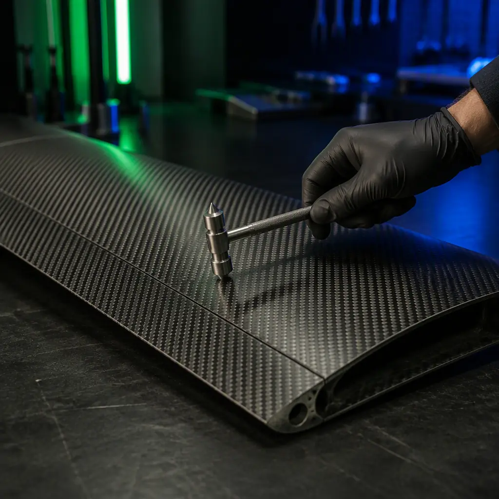
Tap testing (coin tap, or manual tap testing) is the oldest, cheapest and most portable NDT method, and it is still the right first line for UAV fleets. The principle: a tap on a sound laminate rings with a sharp, high-pitched tone; a tap over a delamination, disbond or crushed core produces a dull, low-frequency thud, because the local stiffness has dropped. A trained operator can detect disbonds and near-surface delamination of roughly 10–25 mm diameter in thin skins, and the whole check of a small airframe takes minutes with a coin or a small tap hammer.
What tap testing cannot do: it has no depth resolution (a defect at ply 2 and a defect at ply 8 sound similar), it is subjective (operator-dependent, no quantitative record), and it misses porosity, voids deep in thick laminates and fiber breakage. It is a screening method, not a measurement method. The disciplined version for fleets is a defined tap grid per airframe: every inspection checks the same 30–60 points at the same spacing, and any change in tone on a previously sound point triggers a deeper inspection. The spares and lifecycle planning guide is the framework for scheduling this baseline check into the fleet maintenance calendar, because the interval discipline matters more than the method.
 Concept illustration
Ultrasonic testing: A-scan, B-scan and C-scan
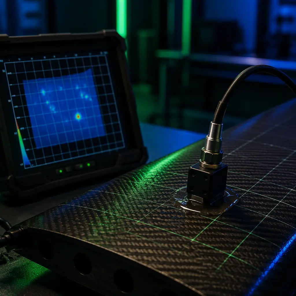
Ultrasonic testing (UT) is the workhorse of composite NDT and the method to move to when tap testing flags a defect or the asset is high-value. A transducer sends a high-frequency pulse (typically 1–10 MHz) into the laminate; the pulse reflects off the back wall and off any internal interface, a delamination, void or disbond reflects early and strongly. The three scan modes serve different purposes:
- A-scan. The single-point time-amplitude display. The operator reads the depth of a reflection directly, the classic tool for confirming and locating a tap-test indication. Portable, cheap, and the natural next step after tap testing.
- B-scan. A cross-section image along a line, depth on one axis, position on the other. Useful for mapping the extent of a disbond along a spar or a leading edge.
- C-scan. The full two-dimensional map of a panel, a top-down image in which each pixel shows the attenuation or reflection at that point, typically color-coded. C-scan is the definitive method for documenting the full extent of delamination or porosity over a surface, and it is what suppliers use for acceptance inspection of new airframes.
The detection limits for UT in thin UAV laminates (1–4 mm skins): delamination of 5 mm and larger in A-scan with a skilled operator, 3–5 mm reliably in C-scan with a proper scan rig, and distributed porosity down to about 1–2% void content by attenuation measurement. Coupling matters. A gel or water couplant is required between transducer and surface, which is why field UT on a dusty airframe is a two-step process: clean, then scan. The electronics manufacturing quality guide makes the parallel point for PCBs, X-ray and automated optical inspection on the board side, but the composite airframe needs its own inspection chain, and UT is its core.
 Concept illustration
Thermography and shearography: large-area screening
When the inspection target is a whole wing or fuselage half, point methods become too slow, and the two large-area methods come into play:
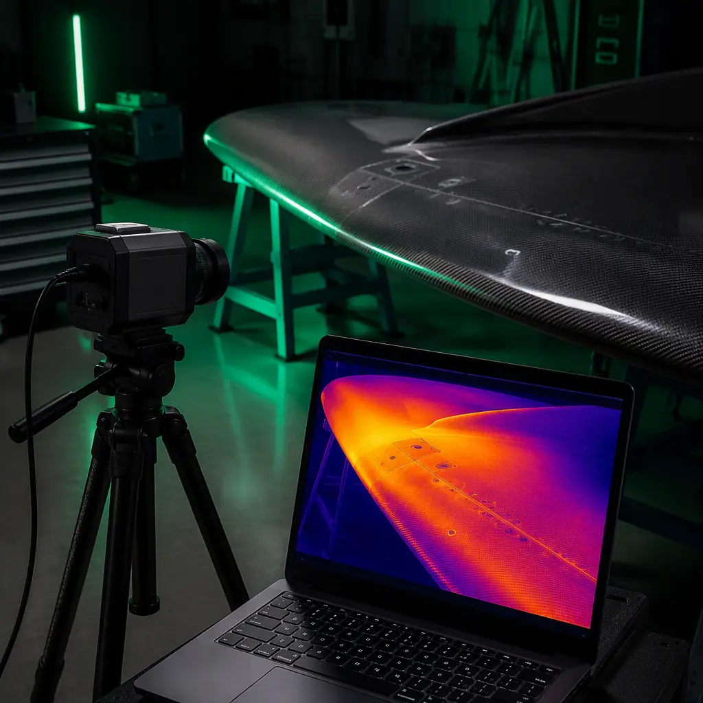
Thermography (infrared testing) flashes the surface with heat (a halogen or flash lamp) and records the cooling transient with an IR camera. Defects act as insulation: a delamination or disbond retains heat longer than sound structure, showing as a hot spot in the thermal sequence. Modern systems detect disbonds and near-surface delamination of roughly 5–15 mm in thin skins, and a full wing inspection takes minutes instead of hours. The limitations: depth penetration is limited (a few millimeters below the surface for quantitative work), and the method prefers thin, single-skin structures. The typical UAV airframe profile, which is why thermography is gaining ground in drone maintenance.
Shearography (speckle pattern interferometry) loads the part slightly, vacuum or thermal load, and measures the resulting surface strain field with a laser interferometer. Any subsurface defect distorts the strain field and appears as a fringe anomaly. Shearography is the aerospace-standard method for honeycomb sandwich disbond detection and can cover a large panel in a single image. It is more sensitive than thermography for disbond in sandwich structures, but the equipment is heavier and the interpretation is a specialist skill, appropriate for depots and suppliers rather than field operators.
The procurement-relevant pattern: tap testing for routine fleet checks, UT for confirmed indications and acceptance inspection, thermography for periodic whole-structure screening, shearography for sandwich-panel assets and supplier acceptance. The environmental monitoring guide and the industrial inspection guide cover the airborne inspection side of the same story. The aircraft that carries cameras to inspect infrastructure needs its own structure inspected with the same discipline.
 Concept illustration
X-ray and CT: seeing the full internal structure
X-ray radiography and computed tomography (CT) are the highest-fidelity composite inspection methods, and they are the acceptance standard for the most critical flight structures. Radiography detects density differences, voids, porosity, fiber distribution anomalies and metallic inclusions, and is fast and cheap per image. CT reconstructs a full 3D volume and can measure void content, fiber orientation and ply-by-ply structure with sub-millimetre resolution, which makes it the definitive method for failure analysis and for qualifying new airframe designs or new suppliers.
The limits are practical: CT requires a lab, a radiation license in most jurisdictions, and an airframe component small enough to fit the scanner volume. Most UAV spars, arms and fuselage sections do fit, but a whole 3 m fixed-wing aircraft does not. The cost per scan is orders of magnitude above tap testing, so CT is reserved for three moments: supplier acceptance of a new design, failure investigation after an incident, and periodic audit of a small sample from a fleet. The obsolescence management guide makes the same sampling argument from the component side, for a fleet that flies for years, the inspection budget follows the same logic as the spares budget: planned, sampled, and tied to the asset's criticality.
Choosing the method: detection capability and cost
The method selection is a four-way trade between detection capability, portability, cost per inspection and the skill required. For a UAV fleet, the practical ladder:
| Method | Best at detecting | Detection limit (thin laminate) | Portability | Cost per airframe |
|---|---|---|---|---|
| Tap testing | Disbond, near-surface delamination | 10–25 mm | Coin / tap hammer | Minutes, no equipment |
| Ultrasonic A-scan | Delamination depth, voids | 5 mm+ (operator-dependent) | Handheld | Low |
| Ultrasonic C-scan | Full delamination / porosity map | 3–5 mm | Scan rig | Moderate |
| Thermography | Disbond, near-surface defects, large areas | 5–15 mm | IR camera | Moderate |
| Shearography | Sandwich disbond, large panels | Sub-mm strain anomalies | Lab / depot | High |
| X-ray / CT | Voids, porosity, internal structure, failure analysis | <1 mm (CT) | Lab only | High |
The operational recommendation for most UAV fleets: tap testing on a fixed grid after every hard landing and on a calendar interval (monthly for daily-flown aircraft), A-scan confirmation of any tap-test change, annual thermography screening of high-value airframes, and CT acceptance or failure analysis for new designs and incidents. The mission planning guide is the reminder that inspection records belong in the fleet database beside flight logs. A fleet that tracks flight hours and landings per airframe can schedule inspections by event and usage, not just by calendar.
Inspection intervals: building NDT into the maintenance program
Composite inspection has no universal interval; it follows the aircraft's exposure. The drivers are: hard landings and ground impacts (the dominant damage source for multirotors), prop strikes, disassembly and handling cycles, exposure to UV and moisture, and the flight hours accumulated at high load. A practical interval framework:
- Event-driven. Tap test the affected area after any hard landing, prop strike, hangar impact or disassembly mishap, before the next flight, not at the next scheduled service.
- Calendar-driven. Full tap-grid sweep monthly for daily-flown aircraft, quarterly for weekly-flown aircraft. The spares and lifecycle guide covers how to fold this into the MTBF-based maintenance plan rather than treating it as an ad-hoc task.
- Annual. Thermography or C-scan screening of high-value airframes, the fleet's flagship aircraft, the ones carrying expensive payloads or flying beyond visual line of sight.
- Post-incident. Any unexplained vibration, trim change, or a flight incident with suspected structural loading triggers a full inspection before return to service. The aviation rule that no UAV fleet should skip because "the aircraft still flies."
The fleet management guide is the operational framework that carries these intervals. The telemetry and maintenance-logging infrastructure that records landings and events so the inspection trigger is automatic. And when an airframe fails inspection or reaches its damage threshold, the lifecycle planning decision applies: repair, replace the component, or retire the airframe, the same cost analysis as any other critical part.
Procurement: clauses that make an airframe inspectable
The most effective NDT program starts at procurement, because inspectability is a design property. Six clauses belong in the RFQ for composite airframes:
1. Manufacturing acceptance data. Every airframe ships with its C-scan (or equivalent) acceptance record, showing void content and the absence of delamination above the agreed threshold. Verification: the scan report with the scan grid and acceptance criteria stated.
2. Layup and material disclosure. The ply schedule, resin system, cure cycle and core material. Because NDT interpretation depends on knowing what is inside. Verification: the material and process specification, aligned with the airframe materials guide.
3. Damage tolerance statement. The manufacturer's statement of allowable damage: what impact energy leaves no detectable damage, what damage is detectable but allowable, and what requires repair. Verification: the damage tolerance test data. This is the number that turns a tap-test thud into a go/no-go decision.
4. Repair documentation. The manufacturer's repair manual, the materials, the cure process and the post-repair inspection method for each repairable area. Verification: the repair procedure document reviewed before acceptance.
5. Inspection accessibility. The design must allow inspection: removable panels, accessible spar caps, drain holes that also serve as inspection ports. Verification: the maintenance manual demonstrates access to every critical bond line.
6. Support for the inspection chain. The supplier's NDT capability and turnaround for depot-level inspections (C-scan, shearography, CT). Verification: the supplier's NDT procedure and facility list, the supplier evaluation checklist is the framework for scoring this response.
The certification and compliance guide adds the regulatory layer: for BVLOS operations and larger platforms, the airworthiness authority increasingly asks for the inspection and maintenance program as part of the operations approval. An airframe with a documented, scheduled NDT program is easier to certify than one with none. A composite airframe is a high-performance structure with invisible failure modes; the inspection program is not overhead, it is the price of the material's advantages.
Explore custom engineering Back to Blog
EMS Drone manufactures composite airframe assemblies under one roof, from component sourcing through production test. If you are specifying for a build, see the full capability set and the tolerances we hold.
Continue Reading
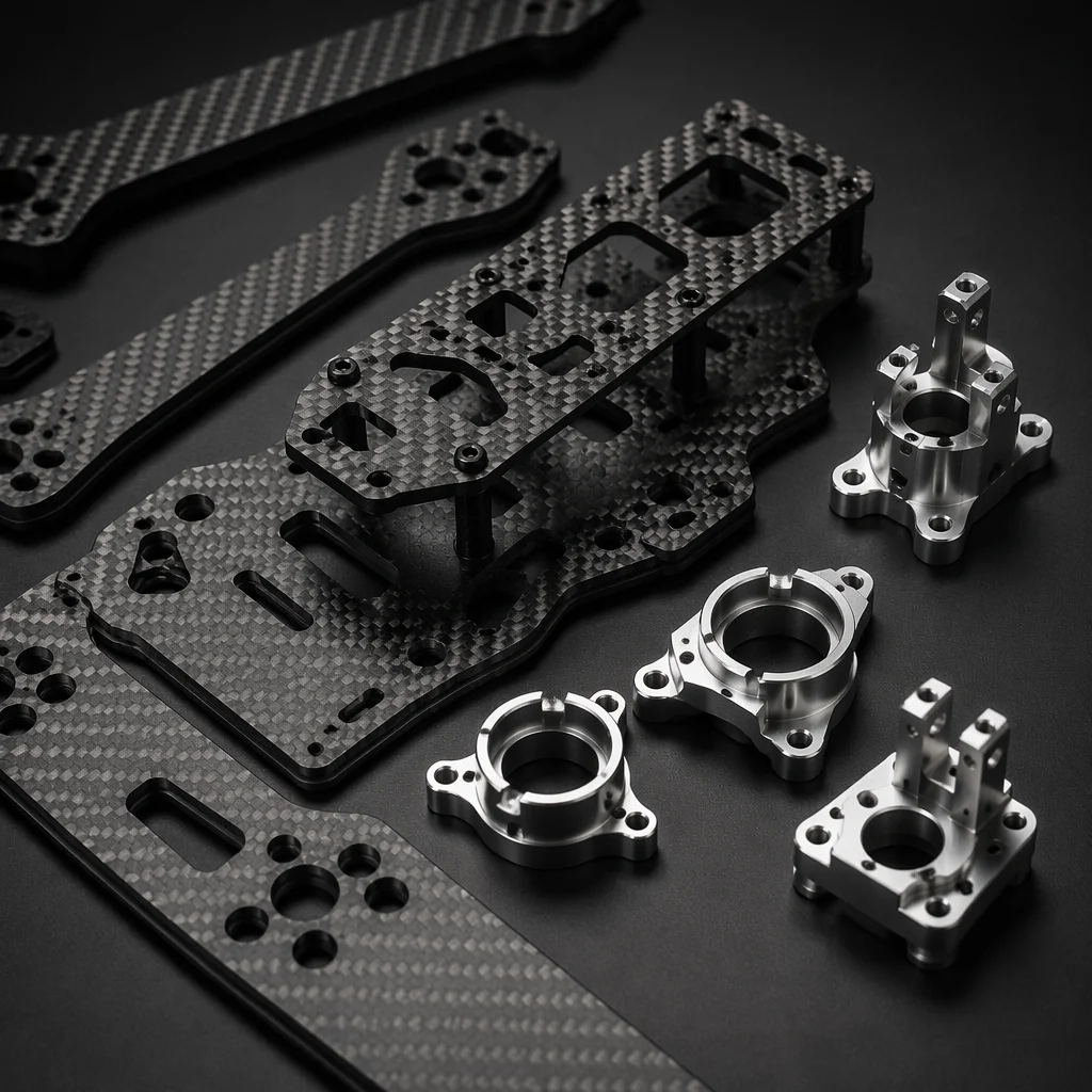
Carbon Fiber vs Aluminum vs G10: UAV Airframe Materials
The material science behind composite airframes, stiffness, weight, manufacturing and the damage behavior that NDT exists to catch.

UAV Spares and Lifecycle Planning
MTBF, spare kits and TCO, the maintenance framework that inspection intervals plug into.

UAV Safety and Redundancy Systems
Why structural integrity is part of the redundancy argument, electronics redundancy cannot save a failed airframe.
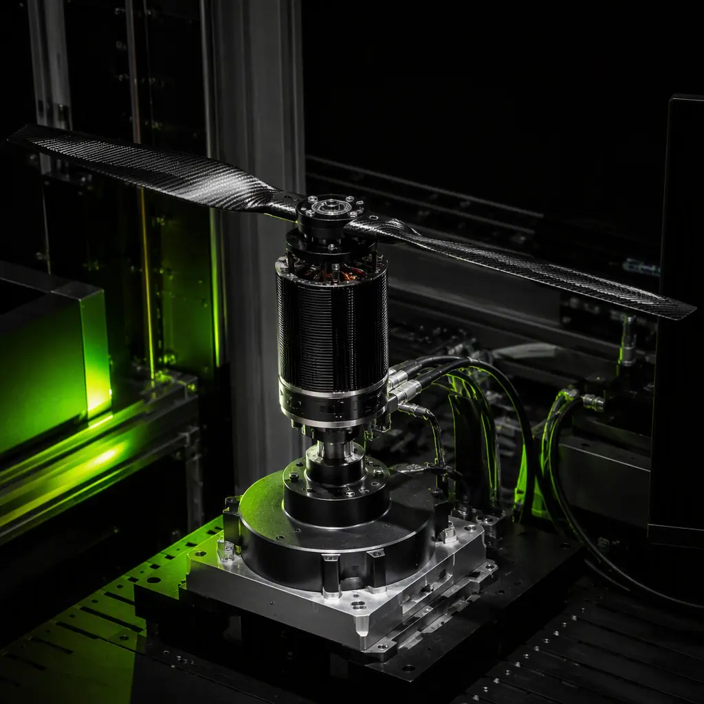
UAV Propulsion Testing and Validation
Thrust stand, thermal and lifetime validation, the propulsion-side testing that pairs with structural inspection.

UAV Fleet Management Components
Telemetry, tracking and maintenance logging, the operational infrastructure that triggers inspections by event and usage.