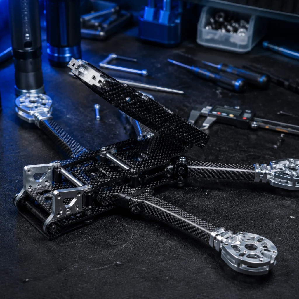
Conceptual UAV airframe structure with carbon fiber arms and center plates Concept illustration
Capabilities / Airframe

Airframes & Structures

The physical skeleton: frame geometry, material selection, structural load paths and mechanical integration for every configuration from micro quads to heavy-lift industrial platforms.

RoleSkeleton of the UAV
ConfigurationsQuad / Hexa / Octo / Fixed-Wing / VTOL
MaterialsCarbon Fiber / Aluminum / Nylon / Composite
DepthFrame Kit → Complete Structure
Overview

The airframe carries every gram of payload and absorbs every Newton of stress.

The airframe is more than a set of plates and arms. It is the structure that defines motor geometry, vibration transmission, crash survivability and thermal management. Getting the frame right means matching wheelbase, arm thickness, plate layup and fastener spec to the aircraft's all-up weight, flight envelope and operating environment. A well-designed airframe adds no unnecessary mass while delivering the stiffness and durability the mission demands.

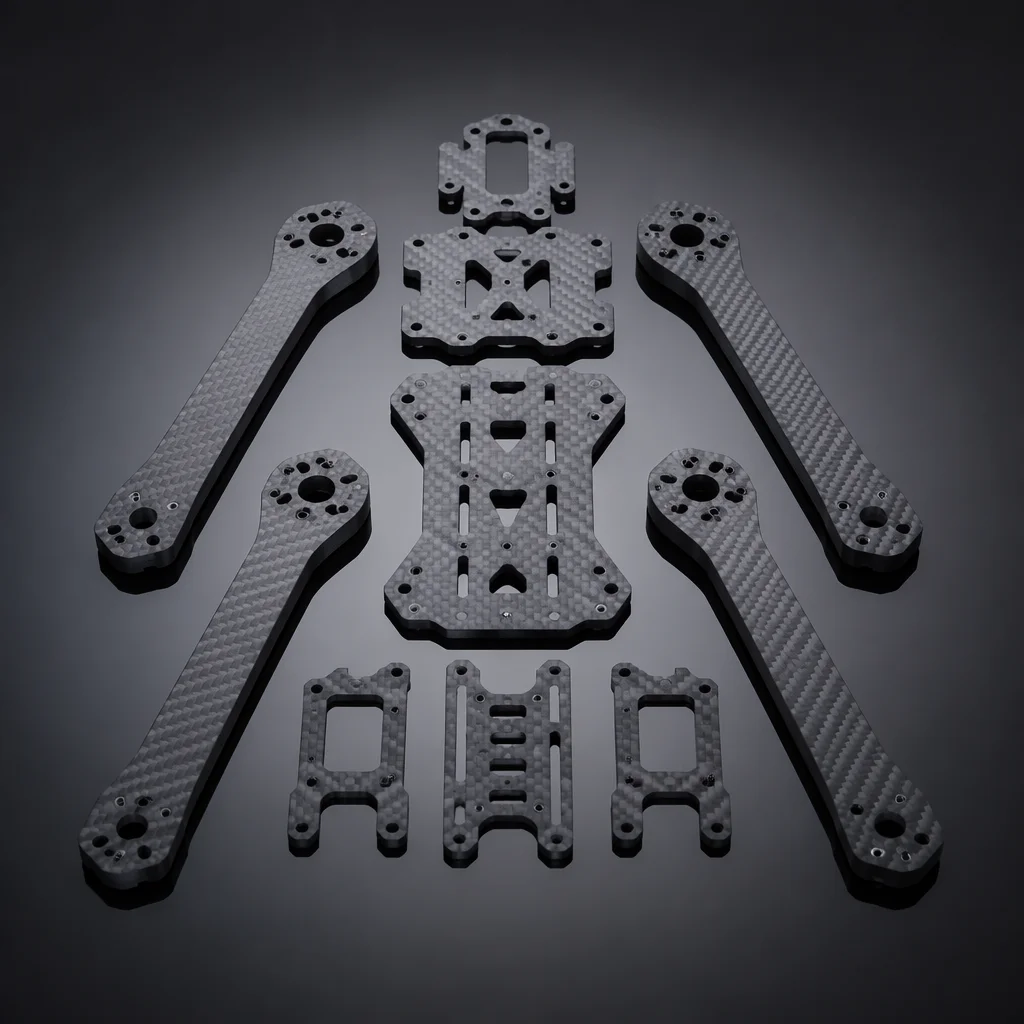
Carbon fiber quadcopter frame with center plates, tubular arms, and motor mounting brackets in exploded view Concept illustration
Frame Platforms

Four platform categories, from agile inspection to heavy cargo.

Each configuration has a distinct structural logic, motor count, arm geometry, mounting interface and load distribution change with the platform.

Quadcopter

Lightweight agility

The most common multi-rotor layout: four motors on two orthogonal arm axes. Frame weight ranges from under 30 g for micro 3-inch builds to 800 g and above for 15-inch-plus heavy-lift platforms. Center-plate stack mounting (30.5x30.5 mm or 20x20 mm) holds the flight controller and ESC stack. Arms are typically removable, clamped or bolted, for field repair. Dead-cat and stretched-X geometries push the front arms forward to keep propellers out of camera view, a critical consideration for cinematography and inspection builds where the camera faces forward.

  • 3–15+ inch
  • 30.5mm stack
  • Dead-cat geometry
  • Removable arms
  • Sub-30g micro
Hexacopter

Redundancy and lift capacity

Six motors in a symmetric arrangement provide motor-out redundancy. The aircraft can maintain controlled flight and land safely after a single motor or ESC failure. This makes hexacopters the default choice for applications where payload value, flight-over-people risk or operational cost of a crash demands redundancy. Typical wheelbases range from 550 mm to 1200 mm, with payload capacities from 2 kg to 25 kg. Yaw authority is stronger than equivalent quadcopters due to the additional counter-rotating motor pairs, improving heading-hold performance in gusty conditions.

  • Motor-out safety
  • 550–1200mm
  • 2–25 kg payload
  • Strong yaw
  • Coaxial option
Fixed-Wing

Endurance through aerodynamic efficiency

Wing, fuselage and empennage structures designed for lift-generated flight rather than thrust-only hover. Fixed-wing airframes achieve 3x to 10x the endurance of an equivalent-weight multi-rotor on the same battery capacity. Construction typically uses molded EPO or EPP foam with carbon fiber spars, or fully composite layups for larger platforms. Wingspan ranges from 600 mm hand-launch mapping platforms to 3 m-plus long-endurance survey aircraft. Motor mount, servo pockets and payload bay geometry are the critical structural integration points.

  • EPO / EPP foam
  • Carbon spars
  • 600mm–3m span
  • Payload bay
  • Belly or rail launch
Custom Geometry

Application-specific structures

When standard frame kits do not fit the mission, unusual motor count (tricopter, octocopter, X8 coaxial), non-planar arm geometry, folding mechanisms for tube-launched platforms, or airframes that integrate payload housings as structural elements. We work from load requirements, motor layout and packaging constraints to specify plate profiles, arm sections, fastener arrays and material stack-ups. Custom geometry also covers VTOL tilt-rotor and tailsitter structures where the airframe must handle both hover and forward-flight load cases without compromising either flight regime.

  • Tricopter / X8
  • Folding arms
  • Tube-launch
  • VTOL hybrid
  • Structural payload
Materials & Construction

Every gram of structure must earn its place in the air.

Material choice determines stiffness-to-weight ratio, vibration damping, fatigue life and manufacturing cost, all in tension with each other.

Primary Structure

Carbon fiber twill, 3K, 6K, 12K

The default material for multi-rotor arms and center plates. Twill-weave carbon fiber sheet (typically 1.5 mm to 6 mm thick for arms, 1.0 mm to 3.0 mm for plates) delivers exceptional stiffness-to-weight ratio. A 250 mm arm weighing under 40 g can support a 1.5 kg thrust motor. 3K weave offers a fine cosmetic finish; 6K and 12K provide higher strength at the cost of slightly coarser surface. Edge finishing (chamfered and sealed) prevents delamination in humid or high-vibration environments. Pure carbon fiber is electrically conductive. Frame grounding and ESC isolation must be considered during design to prevent short circuits through the frame.

Metallic Components

CNC-machined 7075 aluminum

Motor mounts, arm clamps, landing gear brackets and folding mechanisms where carbon fiber cannot provide the necessary thread strength or complex 3D geometry. 7075-T6 aluminum offers tensile strength comparable to mild steel at one-third the weight, yield strength around 500 MPa versus 6061-T6 at 275 MPa. Anodized finishes (Type II for general use, Type III hard anodize for wear surfaces) protect against corrosion. Threaded inserts (stainless steel helicoils, M2.5, M3, M4) are press-fitted into aluminum bosses to prevent galling under repeated assembly cycles and maintain consistent clamp load over hundreds of maintenance cycles.

Non-Structural & Damping

Injection-molded nylon and TPU

Landing gear skids, antenna mounts, GPS mast bases, vibration isolation grommets and protective enclosures use glass-fiber-reinforced nylon (PA6-GF30) for rigid parts and TPU (thermoplastic polyurethane) for flexible, impact-absorbing components. Nylon parts are lightweight, chemical-resistant and cost-effective in production volumes. TPU vibration dampers with Shore hardness A40–A60 isolate the IMU from motor-frequency vibration, a critical detail that directly affects flight controller attitude estimation quality. Dampers are selected to match the dominant motor vibration frequency, typically 100–300 Hz for multi-rotor applications.

Sizing Guide

Wheelbase, motor class, propeller and payload, the four linked dimensions.

Selecting the right frame starts with the payload requirement and works outward. This table provides a reference for multi-rotor sizing from micro to industrial scale.

Wheelbase (diagonal)Frame size from motor center to opposite motor center. Defines the maximum propeller diameter and, together with arm geometry, the aircraft footprint. Larger wheelbases improve pitch and roll stability at the cost of agility and transportability. Common benchmarks: 180–250 mm for 3–5 inch micro/racing; 450–650 mm for 10–15 inch mid-range; 800–1200 mm for 18–22 inch heavy-lift; 1200+ mm for industrial platforms with 24-inch-plus propellers and payload capacities exceeding 20 kg.
Motor size (stator)Stator diameter and height correlate directly with torque output and sustainable current draw. 2204–2207 for 3–5 inch props; 2806–2812 for 7–10 inch; 40xx–50xx for 12–18 inch; 60xx–80xx and above for 20-inch-plus heavy-lift platforms. Taller stators (e.g. 2814 vs 2808) produce more torque at the same diameter, useful for low-RPM efficiency on larger propellers. The motor must physically fit the arm's mounting pattern, M2 screws on 16x16 mm for micro, M3 on 19x19 mm for mid-range, M4 on 25x25 mm or larger for industrial motors.
Propeller max diameterRoughly 40–50% of wheelbase for a quad. A 250 mm frame comfortably runs 5-inch props; a 650 mm frame handles 13–15 inch. Tip clearance between adjacent propeller discs should be no less than 10 mm to avoid blade interaction and acoustic inefficiency. Coaxial configurations (X8) halve the effective propeller area per motor but double the disc loading; prop sizing for coaxials should account for the 10–20% efficiency loss of the lower propeller operating in the upper propeller's downwash.
Payload estimateAs a rule of thumb for multi-rotors: payload capacity is approximately 20–35% of all-up weight for a well-tuned power system. A 5 kg AUW quad can carry roughly 1.0–1.7 kg of payload. Hexacopters can push toward 35–40% at the cost of endurance due to the additional motor and ESC mass. Fixed-wing platforms invert the relationship. The airframe is the smaller fraction of AUW and payload can be 40–60% of takeoff weight, which is why mapping and cargo delivery favor winged configurations for payload-heavy missions.
Arm thickness & width3 mm carbon for up to 5-inch; 4–5 mm for 7–10 inch; 6 mm hollow or 8 mm-plus solid carbon tube for 12-inch and above. Arm width should be at least 3x the motor mount bolt spacing to distribute bending loads into the center plate without stress concentration. Tubular arms (round carbon tube) offer superior torsional stiffness per gram compared to flat plate arms of the same cross-sectional area, and their circular profile presents the same bending stiffness regardless of thrust vector direction.
Integration Notes

Structural integration is where the airframe meets every other system.

These are the key structural interface checks we run for every build. Getting them right at the design stage avoids mechanical rework after assembly.

Stack mounting & vibration isolation

Flight controller and ESC stack mounting must provide both mechanical security and vibration decoupling. Soft-mount grommets (silicone or TPU, Shore A40–60) reduce motor-frequency vibration transmission to the IMU. Stack screw torque should be consistent: typically 0.4–0.6 N-m for M3 nylon standoffs. Over-tightening compresses the damping material and defeats isolation. On larger airframes, a separated IMU module mounted on a dedicated vibration-damped plate further improves attitude estimation accuracy by mechanically decoupling the sensor from frame resonance modes.

Power distribution & wiring routing

High-current paths (battery leads, ESC power wires) should run along arm channels or be secured to frame surfaces with cable ties through dedicated routing holes. Avoid routing power wires parallel to and directly adjacent to compass or GPS cabling. The magnetic field from 30 A-plus DC currents can produce compass errors of several degrees. Center-plate cutouts for XT60/XT90 connectors and capacitor banks should include strain relief features to prevent solder joint fatigue under vibration. Wire gauge must scale with current: 14–16 AWG for 30–60 A ESCs, 12 AWG for main battery leads above 60 A, and 10 AWG for 100 A-plus heavy-lift power systems.

Landing gear & payload hardpoints

Landing gear attachment must handle a minimum 3x aircraft weight in vertical impact, simulating a hard landing, without transferring load into the center plates or avionics stack. Payload rails or quick-release plates should be positioned close to the aircraft center of mass to minimize pitch and roll trim changes when payload is attached. Hardpoint locations in carbon plates should be reinforced with aluminum standoffs or additional carbon doublers to prevent local delamination under repeated load cycling. For retractable landing gear, the actuator mechanism must include end-stop limit switches and a manual override release in case of servo failure.

Environmental protection & corrosion

For operations in rain, coastal salt spray or agricultural chemical exposure: conformal-coated electronics in enclosed center-section bays with drain holes to prevent water accumulation; stainless steel (A2/A4) fasteners throughout to prevent galvanic corrosion between carbon fiber and standard steel hardware. Carbon fiber is cathodic to most metals and will accelerate corrosion of untreated steel fasteners; sealed bearing cartridges in motor mounts; and anti-corrosion treatment on aluminum components. Carbon fiber in direct contact with aluminum requires a barrier layer: typically a thin G10 or glass-fiber isolator, to prevent galvanic corrosion at the dissimilar-material interface.

Related Capabilities

The airframe connects to power, control and payload.

Structural decisions ripple into every other subsystem. These are the most tightly coupled layers.

Flight Control

Stack sizing and sensor placement

Frame stack dimensions, vibration isolation strategy and IMU placement must be coordinated with the flight controller selection. The airframe defines where and how the FC reads the world, mounting location and isolation quality directly affect attitude estimation accuracy.

Flight Control
ESC & Power

Power path and thermal management

Arm channels, center-plate cutouts and cooling airflow paths are designed around the power system layout. ESC placement on the arms or in the center stack affects both weight distribution and component cooling. A decision that must be made at the frame design stage.

ESC & Power
Cost Structure

What airframe cost actually consists of.

Frame cost is quoted as a single number, but it is built from six layers. Buyers who compare only the quoted unit price usually misread which layer dominates their total.

Cost itemOrder of magnitudePrimary driver
Airframe structureUSD 180-900 per unitWheelbase, arm count, carbon layup thickness
Machined fittingsUSD 90-450 per unit7075-T6 motor mounts, arm clamps, folding hardware
Tooling and first articleUSD 1,500-8,000 one timeCNC programs, bonding jigs, alignment fixtures
Fasteners and consumablesUSD 25-80 per unitA2/A4 stainless hardware, barrier layers, adhesives
Integration and verificationUSD 300-1,200 per unitInterface checks, torque records, dimensional report
Spares and field supportUSD 120-600 per yearArm sets, landing gear, replacement fittings

The line most often underestimated is the last two: integration labour and continuing spares. A frame quoted 30 percent cheaper because its arm-to-center-plate interface was simplified typically costs that saving back within the first year in rework and replacement parts, because every field repair is a full disassembly at that same interface.

What an airframe build actually costs, in absolute terms.

The percentages in the structural trade-offs above only become a purchase decision when they are attached to real numbers. The bands below are what we see across carbon-frame programmes of 1,000 mm to 1,800 mm wheelbase, quoted as component build cost rather than as a finished-aircraft price.

Cost itemTypical band (USD)What drives it
Frame structure (arms, plates, fittings)1,800 – 4,500Wheelbase, ply count, number of machined interfaces
Motor mounts and CNC hardware600 – 1,900Motor class, tolerance grade, first-article inspection
Tooling and first-article qualification2,500 – 7,000One-off and amortised across the first 50 frames
Structural validation (static, modal, load-hold)2,000 – 5,500Whether a full test article is sacrificed
Landing gear and ground interface700 – 2,200Skid versus strut, expected touchdown energy
Documentation and traceability400 – 1,200Per-unit torque and dimensional records

The line most often underestimated is tooling and first-article qualification. Buyers treat it as a one-time footnote, but if a design change lands after the first article the qualification cost is paid twice, and on a 50-frame order that can add more to the unit price than the carbon itself.

Which airframe obligations sit with the supplier and which with the operator.

An airframe specification that does not draw this line explicitly will be read differently by every supplier who quotes it. This is the split we hold to.

ItemSupplier responsibilityOperator responsibility
Design load case definitionDocument the margin achieved against the stated caseState the case, including landing impact multiplier
Dimensional conformityFirst-article report per interface, tolerances declaredConfirm the avionics and payload mounting interfaces on receipt
Material and ply scheduleDeclare weave, thickness range and edge sealingVerify repair procedures do not alter the ply schedule
Galvanic isolationProvide documented barrier layer at every carbon-aluminium jointInspect after field repair and after any fastener replacement
Firmware change effect on the frameNotify when an avionics change invalidates the mounting or isolation assumptionRe-run the affected qualification set before fleet firmware upgrades
Structural repairSupply approved repair scheme with the frameApply only the approved scheme; re-verify after any deviation

The firmware-change row is the one that repeatedly gets left out of airframe contracts. A flight-controller update that changes the vibration profile of the control loop can invalidate the isolation work that was signed off against the old tuning, so the obligation to notify has to sit with whoever changes the firmware.

Two frames we engineered, and what their numbers mean for yours.

Both reference builds below use the same structural approach described on this page, and the figures are measured rather than estimated. They are drawn from the capability range we build from, so the trade-offs are the same ones you will face.

  • A coaxial octocopter agricultural platform at a 1,600 mm wheelbase carries 30 L of spray at roughly 25 kg MTOW, with arms built from Ø30 mm carbon tube and CNC aluminium motor mounts. The relevant lesson for a heavy frame is that a coaxial layout reaches that payload at 1,600 mm where a flat eight-rotor layout needs more than 2,100 mm, so the structure saves mass before a single gram of battery is added. See the heavy-lift agriculture reference build.
  • A VTOL fixed-wing mapping platform carries a 5 kg sensor suite on an airframe that sustains 120 minutes of usable endurance, with the belly pod costing 0.8 kg of structure and 12% in parasitic drag. That penalty figure is the one to quote when a payload integration proposal claims a nacelle is “mass-neutral”. See the LiDAR mapping platform reference build.

Read together, the two builds bracket the airframe problem: one shows the mass a coaxial layout saves at fixed payload, the other shows the mass and drag penalty a fixed installation imposes. Neither number is transferable to a different wheelbase, but both are the right order of magnitude to sanity-check a quotation against.

Airframe clauses to write into the requirement document.

Every figure above converts into a clause that can be held to. These are the seven we ask buyers to settle before a quote is meaningful.

  1. State the design load case, including the landing impact multiplier, and require the achieved margin to be documented rather than asserted.
  2. Require arm length, plate hole pattern and motor mount geometry with tolerances, plus a first-article dimensional report.
  3. Declare the carbon weave and thickness range per part, with edge sealing mandatory on every cut face.
  4. Name the aluminium alloy and temper for each machined fitting, and require a documented barrier layer at every carbon-aluminium interface.
  5. Specify fastener grade, torque value and retention method for each joint, with a per-unit torque record.
  6. Include a firmware-change notification clause: the supplier must state when an avionics change invalidates the frame mounting or isolation assumptions.
  7. Require the tooling and first-article qualification cost to be quoted separately, so a change after first article can be priced before it is accepted.

Together these turn the structural discussion on this page into a document a supplier can be measured against. Where the requirement is still open, that is the point at which a configured quotation is worth requesting.

Failure modes we see come back from the field.

Structural problems on small UAVs rarely present as a clean break. They present as a drift in the numbers the flight controller was tuned against. The table below is the return-frequency pattern from airframes we have built and the frames we have inspected after third-party builds, ordered by how often they reach us.

Failure modeShare of structural returnsWhat it looks like in flightDesign fix
Motor-mount plate cracking at the inner bolt circle~30%Rising vibration in one arm, PID loop starts to hunt, eventually a hard oscillationIncrease plate thickness locally rather than globally; specify 7075-T6 with a documented radius at the bolt circle
Carbon-aluminium galvanic corrosion at arm joints~22%No flight symptom until a fastener loses preload and the arm develops playBarrier layer (glass ply or anodised isolation) mandated at every interface, not left to the assembler
Arm-wall delamination after repeated landings~18%Progressive stiffness loss; the first bending mode creeps down toward the rotor bandEdge sealing on every cut face plus a landing-load case in the structural spec
Hole elongation in the centre plate~14%Motor alignment drifts, thrust vectoring changes, endurance drops before anything visibly failsBushings or inserts at load-bearing holes; hole pattern tolerance held in the first-article report
Fastener loosening under vibration~10%Intermittent electrical noise on the arm harness, mistaken for an ESC faultThread-locking method and per-unit torque record written into the requirement
Skin or fairing debonding~6%Cosmetic at first, then a flutter source at high airspeedAdhesive class and cure schedule declared; ambient-cure shortcuts rejected at first article

The pattern matters more than any single row. Slightly over half of all returns trace to two interfaces - the motor mount and the arm joint - which are also the two places where the cheapest possible design still flies, just not for a full service life. When a supplier quotes an airframe without stating which of these interfaces it has designed against, that omission is the risk, not the price. The same interfaces are where we match propulsion to the frame, because a mount that moves under load is a propulsion problem by the time the operator notices it.

Lead time and tooling amortisation, by volume.

Airframe cost conversations go wrong when tooling is treated as a one-off instead of a per-unit cost that changes with volume. The table shows how the same frame breaks down across order sizes. The numbers are indicative for a sub-7 kg platform and are meant to be replaced by a configured quote, but the shape of the curve does not change.

Order sizeTooling and first-article shareTypical lead timeWhat changes at this volume
1-5 units30-45% of unit price5-7 weeksCNC and hand lay-up; tooling never amortises; every unit is effectively a first article
6-25 units15-22% of unit price4-6 weeksCutting and drill fixtures amortise; first-article qualification is still carried by the batch
26-100 units6-10% of unit price3-5 weeksMatched-hole drilling jigs; material bought in sheet lots; inspection moves to AQL sampling
100-500 units2-4% of unit price3-4 weeksDedicated lay-up moulds feasible; per-unit dimensional report can be reduced to a sampling plan
500+ unitsunder 2% of unit pricenegotiatedCompression or resin-transfer moulding becomes economic; design change window closes

Two things follow. First, a buyer comparing a one-off prototype price against a 200-unit price is comparing tooling amortisation, not engineering quality. Second, the design-change window closes as tooling hardens - which is why the requirement document has to be settled at the front, not negotiated after the mould exists. Treating the tooling and first-article cost as a separately quoted line is how a buyer keeps the later-change argument honest.

In-service inspection and re-verification schedule.

A frame that passes first article has not been qualified for its service life; it has been qualified for its first flight. The re-verification schedule below is what keeps a small airframe inside its structural assumptions over hundreds of cycles. None of it is exotic, and all of it is cheap compared with a returned aircraft.

IntervalStructural checkAcceptance criterionEscalation
Every flightFastener witness marks, visible cracks, arm play by handNo witness-mark movement; no perceptible arm playGround the aircraft; do not fly the next sortie on suspicion
25 cyclesTorque check on motor mounts and arm jointsAll fasteners within 10% of specified valueRe-torque, replace any fastener that took more than 90 degrees to reach spec
100 cyclesDimensional spot-check of motor-mount bolt circlesHole position within the first-article toleranceSwap the affected arm; log it as a traceable event
250 cyclesStiffness check - top of the arm deflected by a known loadDeflection within 15% of the as-built figureRemove the arm from service and re-verify the first bending mode
500 cycles or annualFull first-bending-mode re-identificationMode stays clear of the rotor-passing band by the design marginRe-qualify the airframe or retire it; do not retune around a softened frame

The cost of this schedule is a torque wrench and a logbook. The cost of skipping it is discovering a softened frame through a flight incident rather than a bench measurement. Note that the 250-cycle stiffness check is the early-warning step: it is the first point at which a delaminating arm shows up as a number, and it is the reason the as-built deflection figure has to be recorded at first article. A frame whose acceptance data is only "passed" cannot be re-verified later. Running this alongside the production and verification process is what makes the numbers auditable.

What the buyer witnesses at acceptance, per unit.

The acceptance matrix below is deliberately short. It covers the checks that cannot be reconstructed from paperwork after the fact, which are exactly the ones worth witnessing or requiring as documented evidence. The rest of the production record can be reduced to a sampling plan at volume.

CheckMethodRecordCan it be sampled?
Motor-mount hole patternFirst-article dimensional report plus per-batch spot checkCoordinates with tolerancesYes, after first article is approved
Arm joint preloadTorque wrench with a calibrated rangePer-unit torque recordNo - every joint, every unit
Interface barrier layerVisual plus section cut on first articlePhoto plus material certificateVisual every unit; section cut on first article
Edge sealing on cut facesVisual under specified lightingPass/fail with photoYes, at agreed AQL
As-built deflection figureKnown load applied at the arm tipNumeric value retained with the serial numberNo - it is the baseline the service schedule is measured against
Mass and balanceWeigh each unit, record CG against datumPer-unit figuresNo - every unit

The three rows marked "No" are the ones to insist on. They are also the three that a supplier under schedule pressure is most tempted to convert into a pass/fail statement. A per-unit torque record and an as-built deflection figure are what turn the service schedule from a suggestion into an inspection that can actually fail. Buyers who want them written as clauses - rather than assumed - should say so at the engineering intake, because retrofitting per-unit data after the production run is far more expensive than asking for it in the RFQ.

Start With the Structure

Bring the payload class and the operating environment.

Tell us the aircraft configuration, target payload weight, operating conditions and any special structural requirements. We will map the frame platform, material specification and mechanical integration plan to your build.