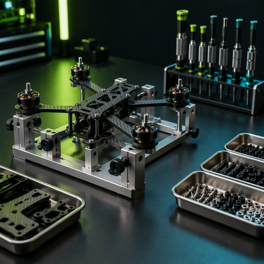
The moment a UAV programme stops being a research project is the moment somebody has to build two aircraft that are genuinely the same. Up to that point every airframe is a one-off, and each one carries the accumulated adjustments of the people who built it: a hole opened slightly to accept a motor mount that was marginally oversized, a harness trimmed after the routing was settled on the bench, a fastener substituted because the specified length was not in the drawer. None of those are defects. Each is a rational decision made by a competent person solving a real problem. The cumulative effect is that the design exists as a set of intentions in the builders' heads rather than as a document, and the second aircraft is the first test of whether those intentions survive being handed to somebody else.
New product introduction is the discipline of converting intent into documentation, and of proving that the documentation produces a conforming aircraft before a production order commits to a batch. It sits downstream of the design work covered in the airframe structural design guide and upstream of the inspection regime covered in the electronics manufacturing quality guide. Its output is not a better aircraft. It is a repeatable one.
What actually breaks between airframe one and airframe fifty
The failures of a UAV production ramp are consistent enough to be predicted, and they cluster into four mechanisms. Knowing which one you are facing determines what to fix.
Tolerance stack-up is the most common and the most misunderstood. A prototype is assembled from parts that were individually within specification, and the assembler resolves any interference by fitting. But a composite airframe is not a set of independent dimensions. Frame stations, motor mounts, the payload interface plane and the GNSS antenna ground plane are all referenced to each other, and the errors accumulate. A frame that is 0.4 mm over nominal at one station and a mount plate that is 0.3 mm over at its own datum produce an assembly with a 0.7 mm mismatch that neither part's inspection record shows, because both parts passed. The dimension that matters is the one the designer cares about, the perpendicularity of the motor axis to the thrust line or the parallel of the payload interface to the fuselage reference plane, and it is a derived quantity that no single part drawing controls.
Process drift without a recorded process. The prototype was bonded with a particular adhesive, at a particular surface preparation standard, in a workshop where the temperature happened to be suitable. None of that is written down, so when production runs in a different bay in a colder month with a new operator, the joint is made differently and nobody notices until a frame delaminates under load. Adhesive bonding is especially vulnerable, because the variables that determine joint strength, surface abrasion, cleanliness, time between preparation and bonding, adhesive mix ratio, cure temperature and clamp pressure, are all invisible in the finished part.
Configuration creep is the accumulation of undocumented changes. A wiring change to accommodate a sensor, a fastener substitution, a different connector because the original had lead time. Six months into a programme the fleet contains aircraft that look identical and are not. This is not a quality problem in itself, it becomes one when a fault appears on one aircraft and cannot be reproduced on another, or when a maintenance instruction is issued that is correct for only part of the fleet. The component obsolescence management guide covers the specific case where the driver is a supplier end-of-life rather than an engineering change, and both cases need the same control: a configuration record that is the truth and a change process that updates it.
Test and acceptance ambiguity. The prototype was accepted because it flew and behaved. What that means numerically was never written down, so the fiftieth aircraft is accepted on the same informal basis, and the first one that is marginally worse flies anyway because there is no threshold to fail against. The propulsion testing and validation guide covers how thrust, thermal and efficiency acceptance limits are established for a propulsion stack; the same principle applies to the aircraft as a whole.
| Failure mechanism | How it appears | Control that prevents it |
|---|---|---|
| Tolerance stack-up | Parts pass individually, assembly does not fit; hand-fitting hides it on the prototype | Assembly-level critical dimensions with a stack-up analysis and a first-article inspection of the joined assembly |
| Process drift | Joints or finishes vary in strength between batches and bays | Written process specification with the variables that matter recorded as parameters, not intentions |
| Configuration creep | Aircraft that look identical are not; faults do not reproduce across the fleet | Configuration record with a change-control procedure and a per-airframe build record |
| Acceptance ambiguity | Marginal aircraft ship because no numeric threshold exists | Declared acceptance criteria with measured values recorded per airframe |
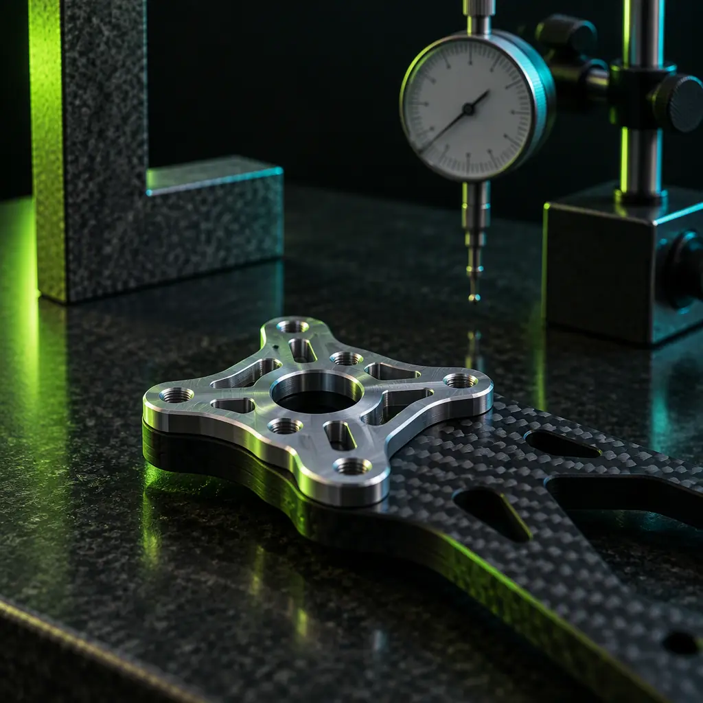 Both parts pass; the assembly does not
First-article inspection: what it is and what it is not
First-article inspection is the verification that the production process, not the prototype process, produces a conforming part, and it is routinely misunderstood as a dimensional check. A first-article inspection that measures the part and compares it to the drawing verifies the part. It does not verify the process, and the process is what production is buying.
A first article that does its job has four components. First, it verifies every dimension and note on the drawing, not a sample, because its purpose is to establish that the drawing and the part agree before production quantities are committed. Second, it records the process parameters used to make it: for a bonded or composite assembly, the surface preparation method, the adhesive batch, the mix ratio, the open time before assembly, the cure temperature and duration and the clamp or vacuum pressure. Third, it records the tooling and equipment identification, so that a later deviation can be traced to a jig or a machine rather than to the part design. Fourth, it is performed on the production tooling. A first article produced on the prototype jig tells you nothing about whether the production jig is capable.
For UAV airframes, the inspection should focus on the dimensions that are derived rather than directly machined, because those are the ones that no part-level check covers. Practical critical characteristics for a multirotor airframe are the flatness and angular alignment of the motor mount planes relative to the frame's thrust reference, the perpendicularity of the motor axis to the rotor plane, the position and parallelism of the payload interface plane, the coplanarity of the landing gear attachment points and the continuity of the GNSS antenna ground plane. For an aircraft with control surfaces, the hinge axis alignment and the symmetry of the control surface deflection range between left and right are the equivalent characteristics. Each of these should be a numbered characteristic on an assembly drawing with a tolerance, and each should be measured on the first article and recorded.
The tolerance stack-up analysis is the companion to this, and it is the document that tells you which part tolerances can be relaxed and which cannot. A stack-up takes the chain of dimensions that produces the critical characteristic, sums the contributions including the geometric tolerances, and shows the expected worst case and the statistical distribution. Its practical value is in the allocation it reveals: if the motor-mount perpendicularity budget is dominated by one frame station's flatness tolerance, tightening that and relaxing a cosmetic dimension elsewhere produces a better aircraft at the same cost. Without the analysis, tolerances are usually tight where they are easy to measure and loose where they are hard, which is the opposite of what the assembly needs.
Writing a build process that survives contact with a second shift
The test of a build process document is not whether the person who wrote it can follow it. It is whether somebody who has never built the aircraft can follow it and produce a conforming result, and whether they can tell when they have not. Most first-generation UAV build instructions fail both.
The specific failure is writing the process as a sequence of intentions rather than parameters. An instruction that says "bond the motor mount with structural adhesive, ensuring good coverage" contains no verifiable information. An instruction that says "abrade the bond face with 120-grit, wipe with isopropyl alcohol, apply adhesive within 20 minutes of preparation, 0.2 mm bond line thickness maintained with 3 mm glass beads, clamp at 0.1 MPa for 24 hours at 20 degrees Celsius or above, inspect for squeeze-out continuity around the full perimeter" is something an operator can execute the same way twice, and something an inspector can check. The variables listed in that example, surface preparation, time from preparation to bonding, bond line thickness control, cure environment and the inspection criterion, are the parameters that determine whether the joint holds. Omitting any of them makes the joint strength a property of the operator rather than of the process.
Two further properties make a process document useful in production. It should have a hold point before any operation that cannot be inspected after the fact. Adhesive bond quality, sealant application inside a closed structure, and the routing of a harness before a cover is bonded on are all irreversible, and each needs an inspection or a photograph taken and recorded before the assembly proceeds. And it should specify the tool for each operation, including the torque specification and the tool calibration requirement. A torque value without the calibration status of the wrench that applied it is not a controlled parameter.
The harness deserves separate mention because it is the component most often left undocumented. A prototype harness cut to length during assembly has no drawing. Production needs one, with a cut length, a routing drawing, a connector schedule identifying each end, a wire gauge and colour code, and a bend radius limit for each segment. The problems an undocumented harness causes are subtle and expensive: a wire routed to a radius tighter than its limit may work perfectly for months before its insulation or conductor fatigues, and a harness that is 40 mm longer than it should be in a fuselage with a tight CG budget is a weight and balance error that accumulates across the fleet. The connectors and power distribution guide covers the selection side of the same subject.
The pilot run and its exit criteria
A pilot run is a small production batch built on production tooling, by production staff, under production documentation, with the specific purpose of finding the process failures before a large batch commits to them. Its size should be large enough to reveal whether the process is stable and small enough that a failure is affordable. For a UAV in the small tens of units, a pilot run of between three and ten aircraft is a practical range: enough to show whether the critical characteristics drift across a batch, and enough to expose the operator-dependency in a process that was written by the people who did the design.
The pilot run's value comes entirely from what is measured during it, and the measurements that matter are the ones that reveal variation rather than the ones that confirm conformance. Every critical characteristic should be measured on every airframe in the pilot run, not sampled, and the results plotted against the airframe number. A dimension that sits at nominal on every airframe is a stable process and its tolerance may be relaxed. A dimension that trends from the first article toward a limit across the batch is a process that is drifting and will produce out-of-tolerance parts in a larger run, even though every aircraft in the pilot run passed. Trend is the signal; conformance is not. This is the reason a pilot run cannot be replaced by inspecting a larger batch and rejecting the failures, because rejecting the outliers does not fix the drift that produced them.
The exit criteria that qualify a design for production should be declared before the pilot run begins, and a workable set is five conditions. One: every airframe in the pilot run met every critical characteristic, measured and recorded, with no hand-fitting to achieve it. Two: the measured variation of each critical characteristic is understood and within the control limit implied by its tolerance, with no unexplained trend across the batch. Three: the build process was executed by staff who did not write it, using the released documentation and the released tooling, without engineering intervention. Every question the production operators had to ask is a hole in the documentation and should be closed before the run is declared successful. Four: a complete build record exists for each airframe, sufficient to reconstruct how it was made and with what materials. Five: the acceptance test was run to the declared numeric criteria on every airframe and the results recorded, including for at least one airframe a repeat of the test at a later date to confirm the result is stable.
When those five conditions are met, the programme has a process it can scale and a documentation set it can defend. When they are not, the honest conclusion is that another pilot run is cheaper than a production order built on an unproven process, because the cost of discovering a stack-up problem at airframe fifty is the cost of fifty airframes, and the cost of discovering it at airframe five is the cost of five.
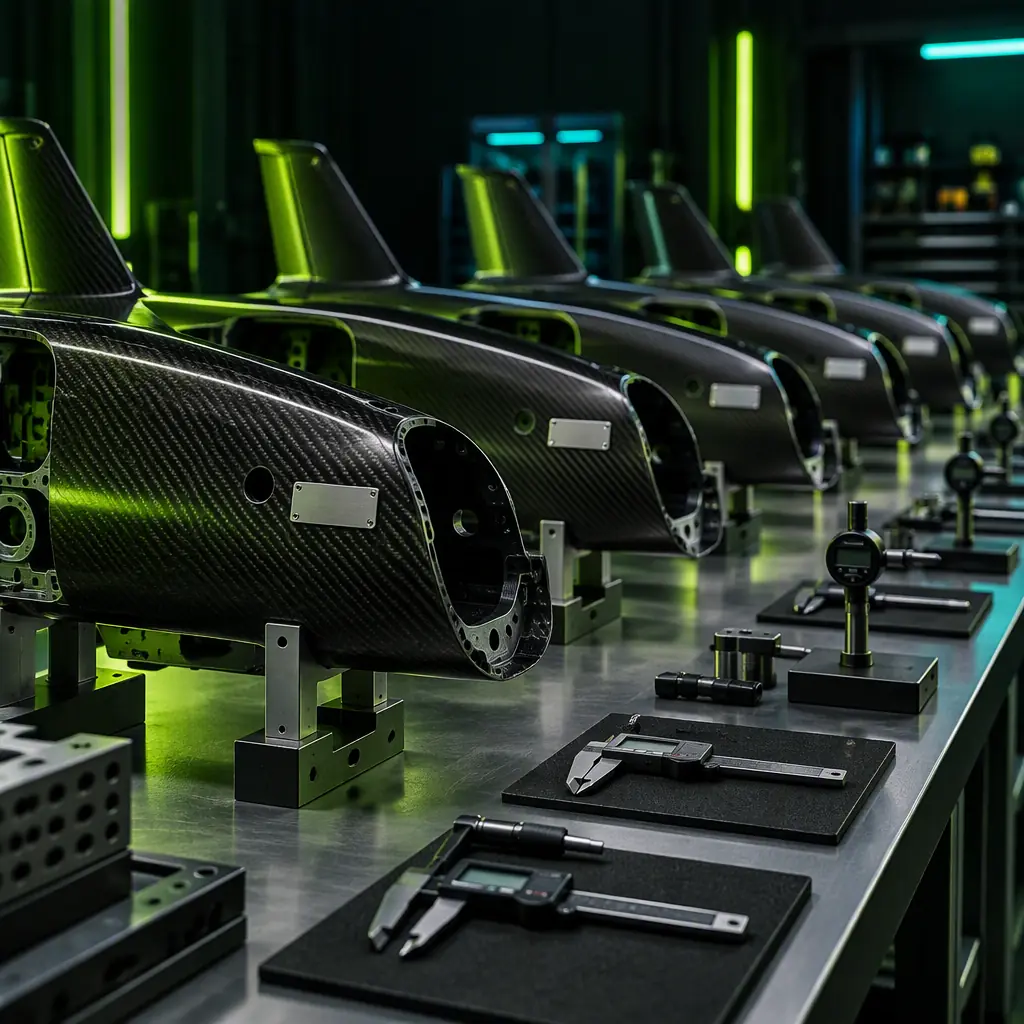 Measure every airframe; watch the trend, not the pass
Procurement consequences and what to ask a build partner
The NPI discipline described above is largely the supplier's responsibility, but the buyer controls whether it happens, because the buyer writes the requirements that make it a contractual obligation rather than a good intention. Five clauses do most of the work.
First, a defined critical-characteristic list agreed before tooling is cut, naming the derived dimensions that matter and their tolerances, with the requirement that each is measured and recorded on a first article and on every airframe. Second, a first-article inspection report as a deliverable, covering the full drawing, the process parameters used and the tooling identification, produced on production tooling and approved before quantity production begins. Third, a process specification for every irreversible operation, including bonding, sealing, potting and harness assembly, with the controllable parameters stated as values and an inspection criterion for each. Fourth, a per-airframe build record with the material batches, the sub-assembly serial numbers and the measured acceptance results, retained for a defined period, because this is the document that makes a warranty claim investigable rather than a negotiation. Fifth, a change-control procedure requiring written notification and approval before any deviation in material, process, tooling or sub-supplier, so that the configuration record stays true. The pre-shipment inspection guide covers the downstream check that what was built matches what was ordered, and the RFP specification guide covers how to word these requirements so that they are testable rather than aspirational.
The bottom line: treat the transition to production as a project in its own right rather than as a scaling-up of the prototype build, identify the derived dimensions that no single part drawing controls and put them on an assembly drawing with a stack-up analysis behind them, require a first article that verifies the process and the tooling and not just the part, write process documents in parameters rather than intentions with hold points before irreversible operations, and run a pilot batch measuring every airframe so that a drift is visible before it becomes a batch of out-of-tolerance aircraft. EMS Drone builds UAV airframes, propulsion stacks and avionics assemblies to customer designs and supports the NPI phase with first-article inspection, tolerance stack-up analysis, documented build processes and pilot-run reporting. Send us your design intent, the critical characteristics that matter to your mission and the production quantity you are planning, and we will return a manufacturability review, the critical-characteristic list with tolerances, and a pilot-run plan with declared exit criteria.
Explore Capabilities Back to Blog
Continue Reading
Manufacturing Quality
IPC-A-610 Class 3, J-STD-001 and the audit that finds real defects.
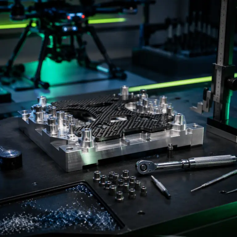
Assembly Tooling
Jigs, fixtures and repeatability in the airframe build.
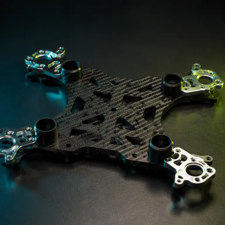
Airframe Structures
Stiffness, modal margin and how loads travel through a frame.
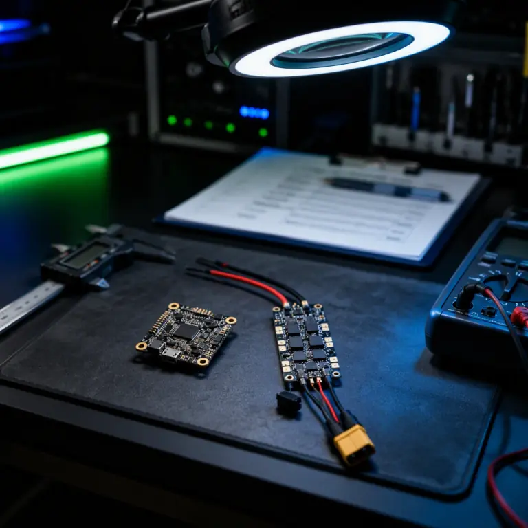
Pre-Shipment Inspection
AQL sampling, defect classes and what to check before release.