
Propulsion system failures are the leading cause of in-flight UAV loss in industrial operations. A motor that delivers 4.2 kg of thrust at 25°C on a freshly charged 12S LiPo may sag to 3.1 kg at 55°C winding temperature on a battery at 3.7 V per cell — a 26% thrust reduction that turns a safe 2:1 thrust-to-weight ratio into a marginal 1.48:1. An ESC rated for 60 A continuous that sees 85 A inrush during an aggressive climb with hot MOSFETs may enter thermal foldback precisely when the aircraft needs maximum power for terrain avoidance. These are not edge cases. They are the predictable outcomes of deploying a propulsion system without validation testing that covers the full operating envelope.
This guide is for engineering and procurement teams who need to validate propulsion components before committing to fleet-scale deployment. It covers the four validation dimensions — thrust stand testing, thermal endurance, ESC reliability, and lifetime prediction — with specific pass/fail thresholds and test duration recommendations. If you have not yet selected your propulsion components, the companion guides on motor KV selection, propeller selection and powertrain matching cover the design-phase decisions that precede validation.
Thrust stand testing: measuring what the datasheet cannot tell you
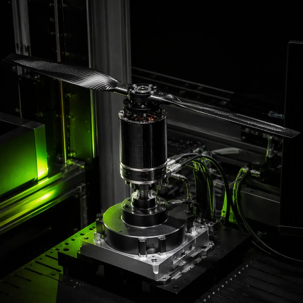
A motor datasheet provides a static thrust table — grams of thrust at 25°C ambient, 4.2 V per cell, with a specific propeller, measured at steady state. This is a starting point, not a validation result. A proper thrust stand test campaign measures the dynamic response: thrust rise time from idle to 75% throttle, efficiency (grams per watt) across the full throttle range, thrust consistency over a 10-minute continuous run, and thrust degradation at elevated winding temperatures.
The minimum test setup requires a load cell rated for at least 150% of the motor's claimed maximum thrust, sampled at 100 Hz or faster. The load cell should be mounted in a pull configuration — motor pulling upward against the cell — to eliminate the effect of the motor's own weight on the measurement. A separate torque sensor or a reaction-torque load cell arrangement provides simultaneous torque and thrust data, which together give you mechanical power output and propeller efficiency. For programs with budget for a commercial solution, the RCbenchmark Series 1585 dynamometer provides 1,500 Hz sampling with ±0.5% accuracy and automated throttle sweep scripts — but a properly calibrated DIY setup with a quality load cell and a data acquisition module achieves 95% of the measurement fidelity at 20% of the cost.
 Concept illustration
The test protocol should include these specific runs. First, a throttle linearity sweep from 10% to 100% in 5% increments, with 10 seconds of stabilization at each step, recording thrust, torque, current, voltage, and RPM at every step. This generates the efficiency curve — grams per watt versus throttle percentage — that tells you where the motor actually operates most efficiently, which is rarely at the claimed peak-efficiency point on the datasheet. Motors in the 100–600 KV range for large industrial multirotors often peak in efficiency between 55% and 75% throttle, not at the 50% midpoint that generic guidance suggests. Second, a thrust step-response test: command an instantaneous jump from 10% to 75% throttle and measure the time to reach 90% of the final thrust value. A properly matched motor-ESC-propeller combination achieves this in under 200 ms with DShot 1200 or CAN FD protocols; slower protocols or impedance mismatches between the ESC and motor can stretch this to 400 ms or more, which matters when the flight controller is commanding rapid attitude corrections. For more on protocol timing, UAV communication protocols covers the latency implications of each signal path.
Third, a 10-minute sustained hover-power run at the throttle percentage corresponding to your aircraft's hover thrust. Measure thrust degradation over the 10 minutes. A healthy propulsion system should show less than 5% thrust drop over this period, assuming adequate cooling airflow. If thrust drops 8% or more at constant throttle, the motor windings are heating up and increasing resistance faster than the propeller can move air through the stator — a sign that the motor is undersized for continuous operation at this power level.
Thermal endurance: keeping the propulsion system within safe limits
Motor winding temperature is the dominant failure mechanism in UAV propulsion. Most industrial brushless motors use N45SH or N48H neodymium magnets rated for 150°C maximum operating temperature, with Class H (180°C) winding insulation. When the winding temperature exceeds 150°C, the magnets begin to partially demagnetize — a permanent damage mode, not a recoverable thermal throttle. The demagnetization reduces the motor's KV — fewer RPM per volt — which the flight controller compensates for by commanding higher throttle, which increases current draw, which increases winding temperature further. This is a runaway failure mode, and it typically manifests on the 40th to 60th flight hour on an undersized motor.
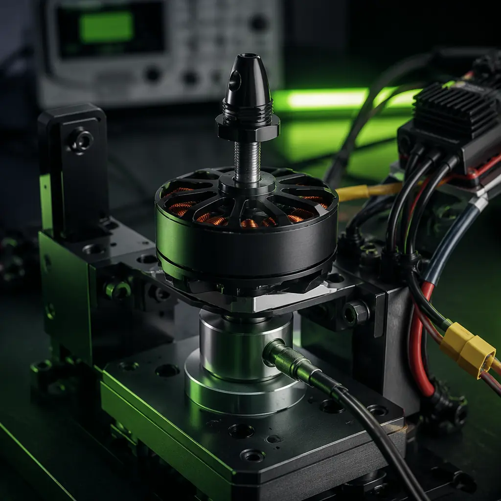
Thermal validation requires instrumenting the motor with a thermocouple on the stator windings — not on the bell or the mount, both of which run 20–40°C cooler than the windings under load. The test protocol: run the motor at hover power for 5 minutes to reach thermal equilibrium, then execute a 60-second burst at maximum continuous power, then return to hover power. Record the peak winding temperature during the burst and the time required to return to the pre-burst equilibrium temperature. For a motor that will see repeated high-power climbs — agricultural spraying where the aircraft climbs to 15 m, transits at altitude, descends, and repeats — the recovery time between bursts determines whether the motor accumulates heat over successive cycles.
 Concept illustration
Acceptance criteria: peak winding temperature during the 60-second burst must remain at least 30°C below the magnet's rated maximum temperature, and the post-burst recovery must return winding temperature to within 5°C of the pre-burst equilibrium within 120 seconds. If either criterion fails, the motor is undersized for the duty cycle. The options are to reduce the maximum continuous power demand (lighter payload, lower climb rate), increase airflow over the motor (duct the propeller wash through the stator more aggressively), or select a larger stator volume motor. For airframe-level thermal considerations beyond the motor itself, the UAV thermal management guide covers the system-level cooling design that affects all avionics components.
ESC validation: beyond the continuous current rating
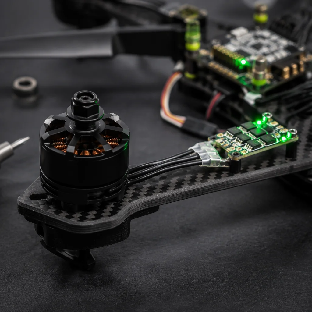
ESC specifications focus on the continuous current rating — 40 A, 60 A, 80 A — but real mission profiles stress ESCs in ways that a static current number does not capture. The three ESC failure modes that validation testing must expose are MOSFET thermal runaway during rapid throttle transients, capacitor bank degradation from sustained ripple current, and protocol-level errors under electrical noise.
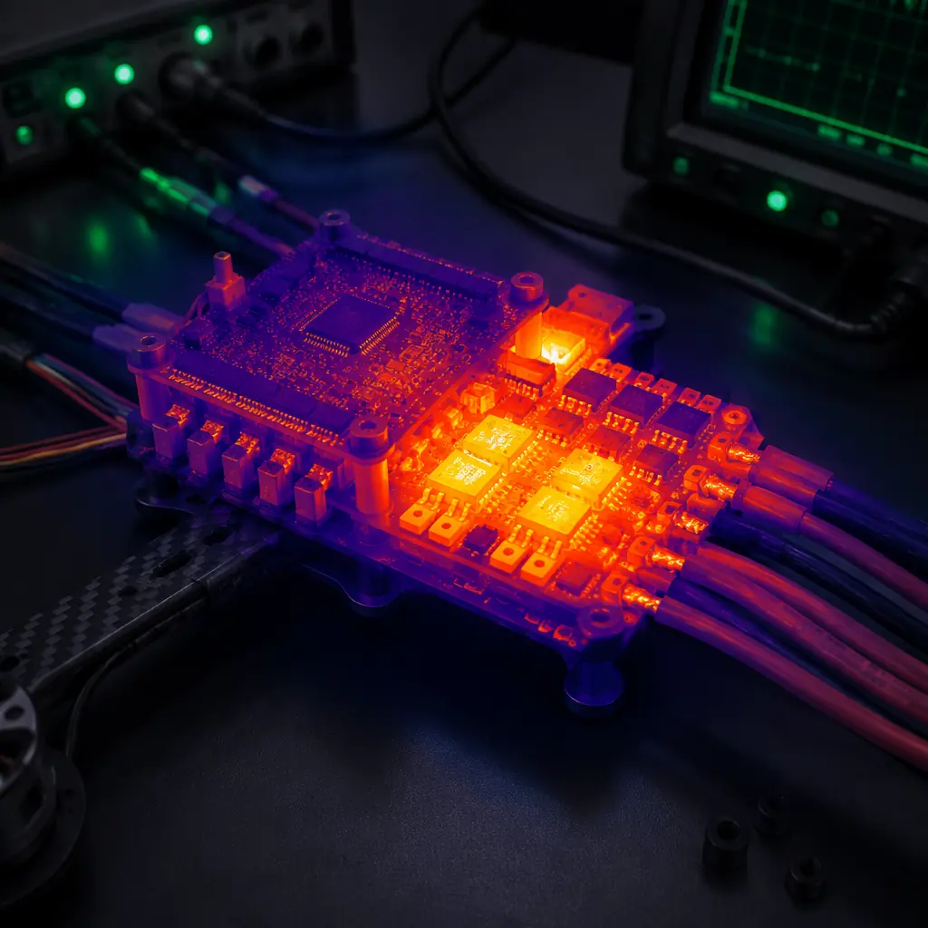
MOSFET thermal runaway testing: configure the ESC to drive the motor through a repeating throttle cycle — 30 seconds at 30% throttle (simulating cruise), 10 seconds at 80% (simulating climb), 5 seconds at 100% (emergency power), return to 30%. Run this cycle for 30 minutes while logging the ESC's MOSFET temperature via its telemetry output. An ESC with adequate thermal design — sufficient MOSFET silicon area, low RDS(on), and adequate heatsinking — should keep MOSFET junction temperature below 120°C throughout the cycle. An ESC that crosses 140°C on the 100% throttle phase is likely to fail within 200 flight hours in field conditions, where ambient temperatures may be higher than the lab and airflow over the ESC may be partially obstructed by the airframe.
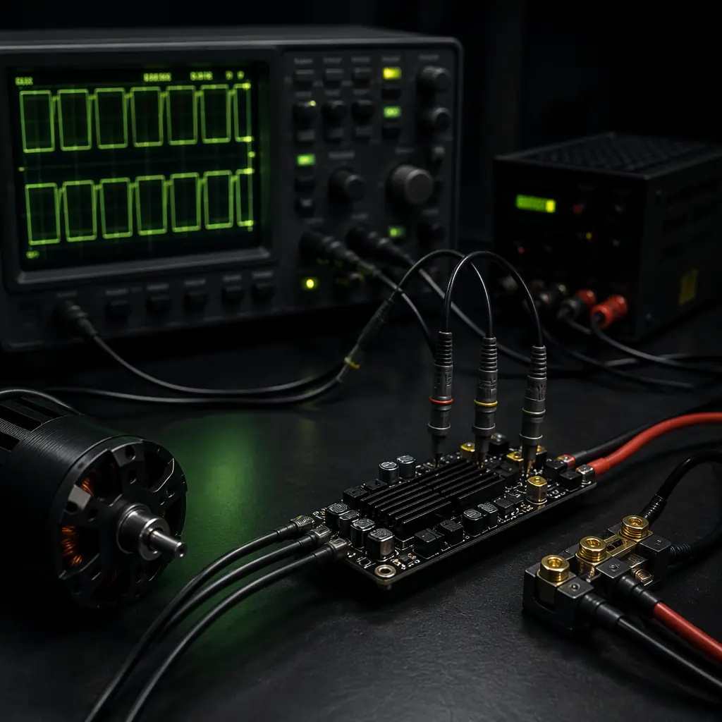
Capacitor ripple current testing is harder to instrument but equally important. The large electrolytic capacitors at the DC input of an ESC smooth the voltage ripple caused by the MOSFET switching waveform. When an ESC operates with long battery leads — common in large UAVs where the battery pack is in the fuselage and ESCs are on the arms — the inductance of the battery leads increases the ripple current the capacitors must handle. The failure mode is capacitor overheating, electrolyte drying, and eventual capacitance loss, which causes voltage spikes at the MOSFETs and sudden ESC failure. The practical test: measure the peak-to-peak voltage ripple at the ESC input terminals during the 30-minute throttle cycle using an oscilloscope probe. Ripple exceeding 5% of the battery voltage (2.5 V peak-to-peak on a 50 V / 12S system) indicates that additional low-ESR capacitance is needed at the ESC input — either a larger capacitor bank on the ESC itself or an additional capacitor module installed at the power distribution board.
 Concept illustration
Protocol-level error testing validates the communication link between the flight controller and ESC. For ESCs using DShot 1200 or CAN FD — the protocols recommended for industrial UAVs in our ESC firmware selection guide — the test involves injecting electrical noise into the signal line and measuring CRC error rates. A practical method: run the motor at 50% throttle, bring a 2.4 GHz telemetry radio antenna within 5 cm of the ESC signal wire, and transmit at full power. Log the ESC telemetry for CRC errors over a 5-minute period. An error rate above 0.1% (one error per 1,000 packets) at this aggressive noise level suggests that the ESC's signal conditioning is marginal and the installation will need additional shielding or twisted-pair signal wiring. For CAN bus installations with multiple ESCs on a shared bus, repeat the test with all ESCs connected and actively communicating — the bus loading from multiple nodes amplifies the effect of noise-induced errors.
Propeller efficiency measurement and structural integrity
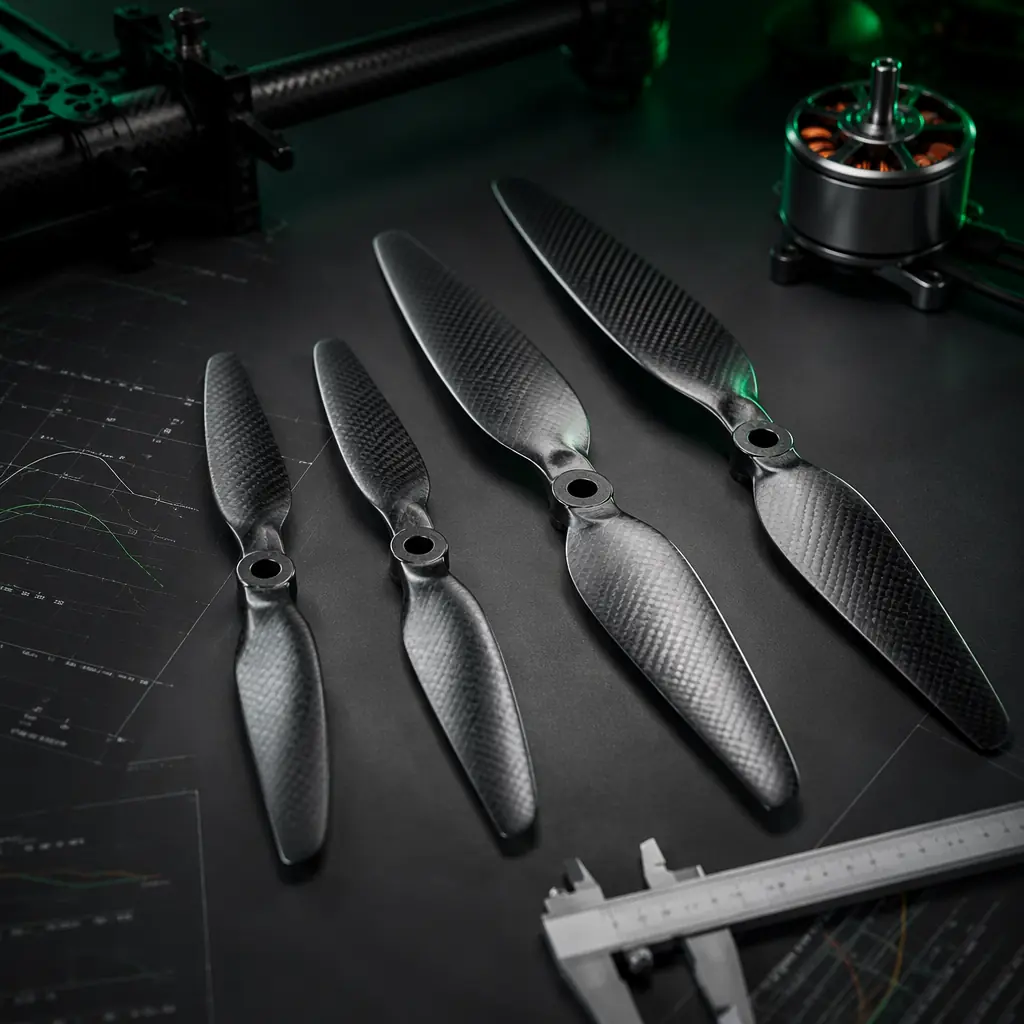
Propeller validation has two dimensions: aerodynamic efficiency and structural integrity. Efficiency testing is straightforward on the thrust stand: measure grams of thrust per watt of electrical input power at each throttle point during the sweep test, and compare the measured efficiency curve against the propeller manufacturer's published data. A well-designed carbon fiber propeller for a 100–600 KV industrial motor should achieve 8–12 g/W at the 50% throttle point. Below 7 g/W, the propeller-airframe combination likely has inefficient inflow — the propeller is operating in partially stalled or turbulent air, often because the motor mount or arm geometry disturbs the inflow.
Structural validation is the test most teams skip, and it is the one that causes the most expensive failures. A carbon fiber propeller spinning at 6,000 RPM stores significant kinetic energy in each blade. A blade separation at cruise RPM sends a carbon fiber projectile through whatever is in its path — often the adjacent motor, the airframe arm, or the battery pack. The structural test protocol: spin the propeller at 120% of its maximum rated RPM for 60 seconds while enclosed in a safety cage (a plywood box lined with Kevlar fabric absorbs a blade strike without becoming shrapnel itself). The propeller should show no visible cracks, delamination, or tip deformation after this test. A propeller that survives 120% overspeed for 60 seconds has adequate structural margin for normal operation at rated RPM.
For folding propellers — common on mapping and survey UAVs that launch from catapults — add a deployment test: spin the motor from 0 to 3,000 RPM in under one second to simulate the centrifugal deployment of the blades from the folded position. Confirm that both blades deploy symmetrically (the propeller should not vibrate excessively during deployment) and that the blade hinge pins show no deformation after 50 deployment cycles. An asymmetric deployment causes a momentary thrust imbalance that the flight controller must correct, and in worst cases the vibration amplitude can saturate the IMU, causing a temporary loss of attitude estimation. For platforms using advanced composite airframes where propeller-induced vibration interacts with structural resonances, the material considerations in the UAV airframe materials guide are directly relevant.
Lifetime prediction: how many flight hours before replacement
The output of propulsion validation is not a pass/fail judgment — it is a predicted service life with quantified confidence. The four test dimensions above produce data that feeds into a lifetime model: at what flight hour does the motor's thrust degrade by 10%? At what flight hour does the ESC's capacitor bank show capacitance loss of 20%? At what flight hour does the propeller's structural margin drop below 110% of rated RPM?
For the motor, bearing life is usually the limiting factor, not winding degradation. Most industrial brushless motors use ABEC-5 or ABEC-7 rated bearings with a theoretical B10 life (the point at which 10% of bearings have failed) in the 500–1,000 hour range under radial and axial loads typical of multirotor operation. But the actual life depends on operating conditions: dust ingestion reduces bearing life by a factor of 3–5, and sustained operation at winding temperatures above 130°C degrades bearing grease and reduces life by a factor of 2. The practical approach: track motor temperature and vibration signature across the fleet. When a motor's vibration amplitude at the blade-pass frequency increases by 50% over its baseline — indicating bearing wear — schedule bearing replacement at the next maintenance interval. This condition-based approach is more cost-effective than a fixed-time replacement schedule.
For the ESC, the dominant lifetime limiter is thermal cycling of the MOSFET solder joints. Each throttle transient — from cruise to climb, from climb to descent — subjects the MOSFET package to a thermal expansion cycle. After approximately 5,000–10,000 thermal cycles at a delta-T of 60°C or more, solder joint fatigue cracks begin to form, increasing the MOSFET's on-resistance and eventually causing thermal runaway. The practical prediction: count throttle transients in your mission profile, estimate thermal cycles per flight hour, and set the ESC replacement interval conservatively at 50% of the predicted cycle life. For an agricultural UAV that executes 20 climb-descent cycles per flight and flies 4 hours per day, that is 80 thermal cycles per day and a 50% life threshold of 2,500 cycles — approximately 31 flight days before ESC replacement should be scheduled.
For propellers, the replacement trigger is visual: any visible crack, delamination, leading-edge erosion deeper than 0.5 mm, or tip deformation visible to the naked eye. For carbon fiber propellers in clean air — mapping UAVs operating at altitude — a 200-hour inspection interval is reasonable. For propellers operating in agricultural environments with chemical exposure or in desert environments with sand abrasion, reduce the inspection interval to 50 hours. For additional guidance on matching propulsion components into a complete system, the powertrain matching methodology provides the system-level integration framework.
Explore our testing services Back to Blog
Continue Reading
Motor KV Selection
Thrust calculation, stator sizing and thermal budget for industrial motors.
Propeller Selection Guide
Diameter, pitch, blade count and efficiency optimization.
UAV Powertrain Matching
System-level matching of motors, ESCs, props and battery.

ESC Firmware Selection
BLHeli_32, AM32 and FOC — protocol choice impacts validation results.
Thermal Management
System-level cooling for flight controllers, ESCs and batteries.