
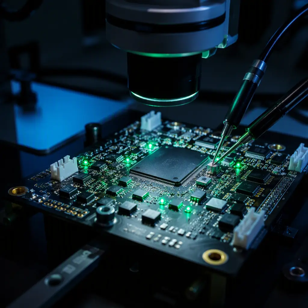
The procurement conversation about UAV electronics usually starts with the component spec — the MCU clock speed, the ESC current rating, the radio sensitivity — and ends at the datasheet. The field failure conversation starts somewhere else entirely: a flight controller that develops intermittent attitude drift after 40 flight hours, an ESC that desyncs only in hot weather, a telemetry module that loses packets when the airframe vibrates. All three are manufacturing-quality failures: marginal solder joints that pass a bench test and fail under thermal cycling, flux residue that conducts under humidity, a BGA void that cracks when the board flexes. The datasheet cannot tell you which one you are buying. The manufacturing evidence can.
Why UAV electronics fail: the defect classes that never appear on a datasheet
UAV avionics fail differently from consumer electronics because the operating environment is more brutal: continuous vibration across the propulsion band, thermal cycles from −20°C ground soak to 60°C+ internal temperatures during flight, humidity and condensation inside sealed compartments, and high-G landing shocks. The defect classes that dominate field returns are exactly the ones that pass a single bench test at the factory:
Intermittent solder joints. A solder joint with insufficient wetting, a hairline crack or an excessive void passes a resistance test at 25°C and fails at −10°C or under vibration. The classic failure signature is a board that works on the bench, fails in flight, and passes again when the technician reflows it with a hot-air station. The manufacturing controls are the acceptance criteria (IPC-A-610), the process (J-STD-001) and the inspection coverage (AOI plus X-ray for BGA and QFN packages).
Contamination and residue. Flux residue left on the board absorbs moisture and creates ionic conduction paths between pins — the failure appears as intermittent brownouts, sensor noise or ESC misfires that correlate with humidity. The manufacturing control is the cleaning process and the ionic contamination test (the ROSE test per IPC-TM-650, with a typical acceptance limit of 1.56 µg/cm² NaCl equivalent on the final clean board).
Component-level defects. A counterfeit or substandard IMU, a memory chip from a questionable lot, or a MOSFET operated inside a derating margin that the manufacturer quietly relaxed. The manufacturing control is component sourcing discipline, date-code and lot traceability, and incoming inspection (IQC) with the original manufacturer's verification.
Handling and ESD damage. Bare-hand handling of a Class 3 board, an ungrounded workstation or a missing ESD bag can damage components in ways that pass final test and fail in the field. The manufacturing control is the ESD program (ANSI/ESD S20.20) and the handling rules that IPC-A-610 Class 3 inspection enforces.
The procurement consequence: quality is specified, not assumed. The rest of this article gives you the specification language, the verification evidence and the audit questions.
 Concept illustration
IPC-A-610 Class 2 vs Class 3: what the acceptance criteria actually change
IPC-A-610 is the worldwide acceptance standard for electronic assemblies — it defines what a good solder joint looks like and what a reject looks like, across three classes. Class 1 (general electronics) accepts cosmetic imperfections that Class 2 rejects. Class 2 (dedicated service electronics) is the commercial default — the phone, the laptop, the consumer drone. Class 3 (high-performance/high-reliability electronics) is the class for equipment that must keep operating in the field — flight avionics, medical devices, military electronics. UAV flight controllers, ESCs, power distribution boards and communication modules used in commercial operations should be built and inspected to Class 3. The differences are concrete, not marketing:
Side fillet height on surface-mount leads. For a gull-wing lead, Class 2 accepts a minimum side fillet height of 50% of the lead thickness; Class 3 requires 75%. The taller fillet is the difference between a joint that survives thermal cycling and one that develops a fatigue crack after hundreds of cycles. The inspection is visual (under magnification) and, for the critical joints, verified by AOI.
Wetting and dewetting. Class 2 permits minor dewetting on the termination end; Class 3 requires complete wetting of the solderable surfaces with no exposed base metal on the termination ends. Dewetting is the signature of a marginal solderability problem — the joint looks soldered but the metallurgical bond is incomplete.
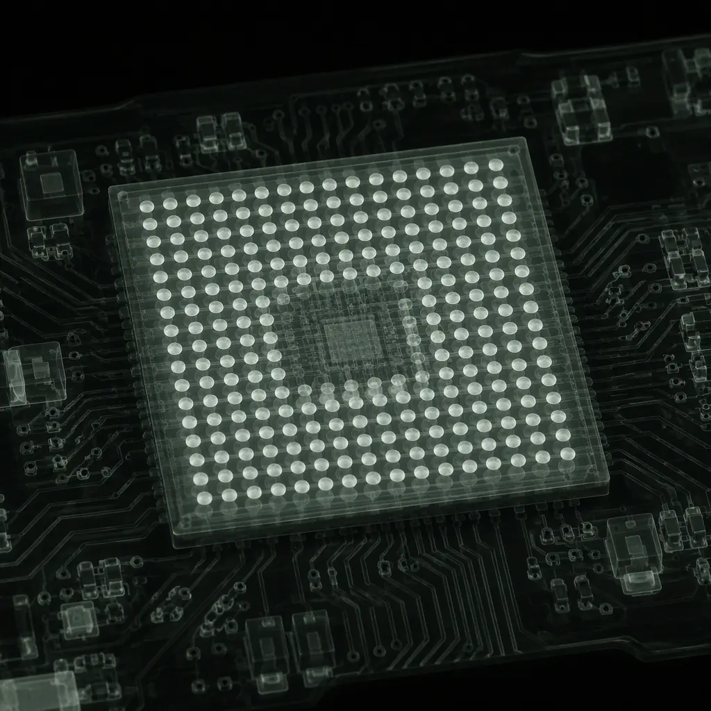
BGA voiding. Voiding inside BGA solder balls is invisible to visual inspection and detectable only by X-ray. IPC-7095 guidance for high-reliability BGA assemblies recommends keeping voiding below 25% of the ball cross-section, and Class 3 programs typically enforce an X-ray sampling plan on every board with BGAs and QFNs. A large void under a BGA ball creates a hot spot, reduces current-carrying capacity and provides a crack initiation site under thermal cycling.
Handling and workmanship. Class 3 inspection enforces glove or finger-cot handling, no bare-hand contact with the board surfaces, controlled storage of moisture-sensitive devices (MSL bake requirements), and restrictions on rework — typically a maximum of two rework cycles on a pad before the board is dispositioned. The handling rules are invisible in the final product but predict its long-term reliability.
Inspection intensity. Class 3 programs apply 100% inspection of the critical criteria (via AOI plus operator verification), documented first-article inspection, and a tighter sampling plan on the process-control attributes. The cost is real — Class 3 acceptance typically adds 15–30% to the assembly cost per board and 2–4 days to the lead time for a flight controller — which is exactly why the class must be written into the RFQ and verified in the audit, not assumed.
The UAV certification and compliance guide covers how the Class 3 manufacturing evidence fits into the CE, FCC and airworthiness documentation package for exported platforms, and the UAV supplier evaluation checklist turns these acceptance criteria into an audit script you can run in a factory visit.
J-STD-001: solder joint quality, materials traceability and the workmanship chain
Where IPC-A-610 defines the acceptance of the finished assembly, J-STD-001 defines the process that produces it: the soldering requirements, the materials control, the cleanliness verification and the process control records. The two standards are used together — J-STD-001 for the process, IPC-A-610 for the product — and a supplier that quotes "IPC Class 3" should be able to show both the process documentation (J-STD-001) and the acceptance records (IPC-A-610).
Materials control. J-STD-001 requires the solder alloy, flux and cleaning agents to be specified and controlled. For UAV avionics the relevant detail is the solder alloy: lead-free SAC305 (Sn96.5/Ag3.0/Cu0.5) is the default, but the higher operating temperatures and vibration environment of UAV power electronics are one of the applications where a tin-lead or high-reliability alloy is sometimes specified for the high-current joints. The requirement is that the alloy, the flux chemistry and the reflow profile are documented and consistent — an undocumented alloy change is one of the most common silent reliability regressions in contract manufacturing.
Cleanliness verification. J-STD-001 section 8 requires the assembled board to be cleaned to a defined level and verified. The standard method is the ROSE (Resistivity of Solvent Extract) test per IPC-TM-650 method 2.3.25, with the widely used acceptance limit of 1.56 µg/cm² NaCl equivalent on boards that will be conformal-coated. The test matters because the flux residue that looks harmless under a microscope becomes a leakage path under humidity — the failure mechanism behind the "works on the bench, brownouts in the field" pattern in agricultural and marine UAV platforms. The cleaning specification for the flight controller and ESC boards should be written into the RFQ as a numeric limit, not a process description.
Process records. J-STD-001 requires traceable process control: the reflow profiles, the solder paste print inspection (SPI) results, the rework records and the operator certifications. The audit value of the records is that they let you verify the process did not drift between your first article and your production lot — the reflow profile from last week's run, the SPI pass rate, and the AOI coverage on your specific board revision.
The interaction between soldering quality and the other reliability domains is covered across the site: the thermal management guide explains why the solder joint is the thermal bottleneck in high-current ESC design, the EMC/EMI design and compliance guide covers the PCB-level layout and shielding that manufacturing must preserve, and the connectors, wiring and power distribution guide covers the harness-side workmanship that the J-STD-001 discipline extends to.
 Concept illustration
The inspection layers: AOI, X-ray, ICT, functional test and the escape-rate math
No single inspection catches every defect. The manufacturing quality of a UAV avionics board is the product of the inspection layers stacked on top of each other, and the escape rate (the defects that reach you despite inspection) is a function of the layer coverage. The procurement specification should name the layers and their coverage, not just "100% testing":
SPI (solder paste inspection). 3D measurement of the paste deposit before reflow — volume, height, area and alignment on every pad. Paste defects (insufficient paste, paste bridges, misalignment) are the root cause of most reflow defects, and SPI is the cheapest layer to catch them. A serious supplier runs SPI on every board with a 3D system.
AOI (automated optical inspection). Post-reflow 2D or 3D optical inspection of every visible joint — missing components, tombstoning, solder bridges, insufficient or excessive solder, wrong polarity, wrong component. AOI catches the visible defects at high speed; its blind spot is anything under a package (BGA balls, QFN pads) and anything that looks right optically but is cracked internally.
X-ray / AXI. Inspection of the hidden joints — BGA and QFN voiding, solder ball collapse, head-in-pillow defects. For boards with BGA packages (common on the latest flight controllers with dense SoCs and on companion computers for edge AI), X-ray inspection is not optional: the head-in-pillow defect — where the solder ball melts but fails to fuse with the paste — passes AOI completely and produces an intermittent failure that appears after thermal cycling. The UAV edge AI and onboard computing guide covers the dense-package boards where X-ray inspection matters most.
ICT (in-circuit test). Electrical verification of every node on the board through a bed-of-nails fixture — opens, shorts, missing components, wrong values, and basic device function. ICT catches the electrical defects that optics cannot see. Its limitation is that it verifies the board, not the system.
Functional test. The board powered up and exercised as a system: for a flight controller, the IMU initialization and bias calibration, the barometer readout, the PWM and DShot outputs, the CAN bus traffic, the telemetry link; for an ESC, the throttle sweep, the current draw, the commutation at speed, the thermal shutdown behavior. A 100% functional test with recorded results — the pass/fail data, not a sticker — is the layer that catches the interaction defects.
Environmental screening. For the components that will see the harshest duty — the propulsion ESCs, the power distribution board — thermal cycling and burn-in screening (per IPC-9701 for solder joint reliability, or a burn-in soak of 12–48 hours at elevated temperature) shifts the early-life failures out of the field and into the factory. The cost is real and the specification should be explicit about which boards get screened.
The escape-rate math works like this: a flight controller with 800 solder joints, a process defect rate of 20 ppm per joint and no inspection escapes roughly 1.6% of boards with at least one defective joint. Add SPI and AOI (which catch 90–95% of the visible defects), X-ray on the BGA joints, ICT and a 100% functional test, and the effective escape rate drops to well under 100 ppm of boards — but only if every layer actually ran on every board and the results are recorded. The audit question is never "do you have an AOI machine" — it is "show me the AOI results for the last lot of my board, and the defect Pareto over the last three months".
 Concept illustration
Cleaning, conformal coating and the contamination failures
The cleanliness of a UAV avionics board interacts directly with the environmental protection package. A board that leaves the factory with flux residue and then receives conformal coating has the contamination sealed in — the residue absorbs moisture under the coating, and the failure appears as intermittent behavior in high-humidity missions that is almost impossible to diagnose because the coating hides the contamination. The manufacturing specification must therefore sequence the quality steps correctly:
Clean before coat. The ionic contamination limit (1.56 µg/cm² NaCl equivalent per the ROSE test) should be verified before the conformal coating is applied. The coating process itself is specified under IPC-CC-830 (the coating chemistry and application) and inspected under IPC-A-610 (the coverage and the masked areas). The waterproofing and IP-rated components guide covers the coating chemistries, the thickness ranges and the masking requirements in detail — the manufacturing-quality angle here is that the coating is only as good as the board it covers.
Underfill for the fragile packages. For the ball grid array and chip-scale packages on the flight controller and the companion computer, underfill (the epoxy that locks the package to the board) prevents the solder balls from cracking under vibration and thermal cycling. Underfill is a manufacturing process with its own material and cure controls, and its absence is invisible in final test — the failure appears after hundreds of flight hours. The RFQ should state which packages receive underfill and require the process record.
The wash process. The cleaning chemistry (water-based, semi-aqueous or solvent), the wash cycle and the verification must be documented. The ROSE test result is the acceptance evidence — a numeric limit, not an assurance.
The contamination and coating failure modes are the same ones that drive the sensor fusion and redundant navigation reliability discussion: the avionics must maintain its accuracy not just on the bench but after months of field exposure, and the manufacturing quality determines how long the board keeps its specification.
Quality systems: ISO 9001, AS9100 and what an audit can and cannot prove
The quality-system certificate is the entry ticket, not the evidence. ISO 9001:2015 certifies that a supplier has a documented quality management system — it does not certify the Class of the boards, the inspection coverage or the traceability depth. AS9100D (the aerospace add-on to ISO 9001) adds the requirements that matter for flight hardware: configuration management, first-article inspection per AS9102, counterfeit-parts prevention, FOD (foreign object debris) control, and tighter traceability. For UAV avionics in commercial operations, AS9100 is the stronger signal, but the certificate alone still proves little — the audit evidence is in the records:
First-article inspection (FAI). Per AS9102, a complete dimensional, material and process verification of the first production article against the drawing and the spec. The FAI report for your board revision — not the supplier's generic FAI for a different board — is the first document to request. It proves the board was actually built and inspected against the criteria you specified.
Lot traceability. The ability to trace a serialized board to its component lots (the IMU date code, the memory lot, the solder paste lot) and to its process records (the reflow profile, the AOI results, the functional test data). Lot traceability is what turns a field failure into a containment decision — "which boards are affected" — instead of a whole-fleet gamble. The component obsolescence management guide covers the related question of how the component lots and the lifecycle status interact with the maintenance plan.
Corrective action history. The supplier's 8D or CAPA records over the last 12 months — what failed, what was found, what changed. A supplier with no corrective actions in a year is either excellent or not looking; the audit question is the depth of the analysis, not the count.
What the audit cannot prove. An audit is a point-in-time sample. The certificate, the FAI and the records prove the capability; they do not prove that this week's production lot ran to the same standard. That is what the lot-level evidence — the SPI and AOI results, the X-ray sampling, the functional test data for your serial numbers — is for, and why the delivery documentation should include it with every shipment.
The procurement decision context — when to buy from an assembler versus a manufacturing partner, and what the difference costs — is covered in the UAV component sourcing: build vs buy guide, and the end-to-end supplier qualification process in the supplier evaluation checklist.
 Concept illustration
The RFQ checklist: 12 line items for specifying manufacturing quality
The following twelve line items translate the manufacturing-quality discussion into an RFQ-ready specification. Each line item includes the evidence the procurement team should collect before acceptance, and the checklist works for flight controllers, ESCs, power distribution boards, communication modules and payload electronics alike.
1. Acceptance class. All avionics assemblies shall be built and inspected to IPC-A-610 Class 3 and J-STD-001 Class 3. Verification: the FAI report (AS9102 format) for this board revision, referencing the Class 3 criteria.
2. Solder joint criteria. The side fillet height on surface-mount leads shall meet the Class 3 minimum (75% of the lead thickness on gull-wing leads), with no dewetting and no exposed base metal on termination ends. Verification: the AOI results and the operator inspection records for the last production lot.
3. Hidden-joint inspection. All BGA and QFN packages shall be X-ray inspected with voiding below 25% of the ball cross-section. Verification: the X-ray images and the disposition records for each board in the lot.
4. Solder paste inspection. Every board shall pass 3D SPI before reflow, with the paste volume, height and alignment within the process window. Verification: the SPI statistics for the lot (the Cpk or the pass rate).
5. Cleanliness. The final clean boards shall pass the ROSE test per IPC-TM-650 2.3.25 at ≤ 1.56 µg/cm² NaCl equivalent before conformal coating. Verification: the ROSE test report with the board serial numbers.
6. Conformal coating. The specified boards shall be conformal-coated per IPC-CC-830 with the chemistry, thickness and masking documented, and the coating thickness verified on process coupons. Verification: the coating process spec and the thickness records. The coating interaction with thermal performance is covered in the thermal management guide.
7. Underfill. The BGA and chip-scale packages on the flight controller and the companion computer shall be underfilled with the material and cure schedule documented. Verification: the underfill process record.
8. In-circuit test. Every board shall pass ICT covering opens, shorts, component values and device function on all nodes. Verification: the ICT fixture coverage report and the lot pass rate.
9. Functional test. Every board shall pass a 100% functional test at operating voltage and temperature: the IMU initialization and bias, the PWM/DShot/CAN outputs, the telemetry link, the current draw and the thermal behavior. Verification: the recorded functional test results per serial number.
10. Environmental screening. The propulsion ESCs and the power distribution boards shall receive thermal cycling or burn-in per the agreed profile. Verification: the screening profile and the results.
11. ESD and handling. The assembly line shall operate an ANSI/ESD S20.20-compliant ESD program with grounded workstations, and the boards shall be handled with gloves per the Class 3 handling rules. Verification: the ESD program documentation and the audit records.
12. Traceability and delivery documentation. Each serialized board shall be traceable to its component lots and its process records, and the shipment shall include the FAI report, the lot-level inspection statistics, the functional test data and the corrective-action history relevant to the board. Verification: the delivery documentation package.
For the test bench and acceptance-test methodology that verifies the assembled propulsion and power hardware — the thrust, the thermal and the endurance data that complement the manufacturing evidence — the UAV propulsion testing and validation guide covers the full framework.
Explore custom engineering Back to Blog
Continue Reading
How to Evaluate a UAV Component Supplier
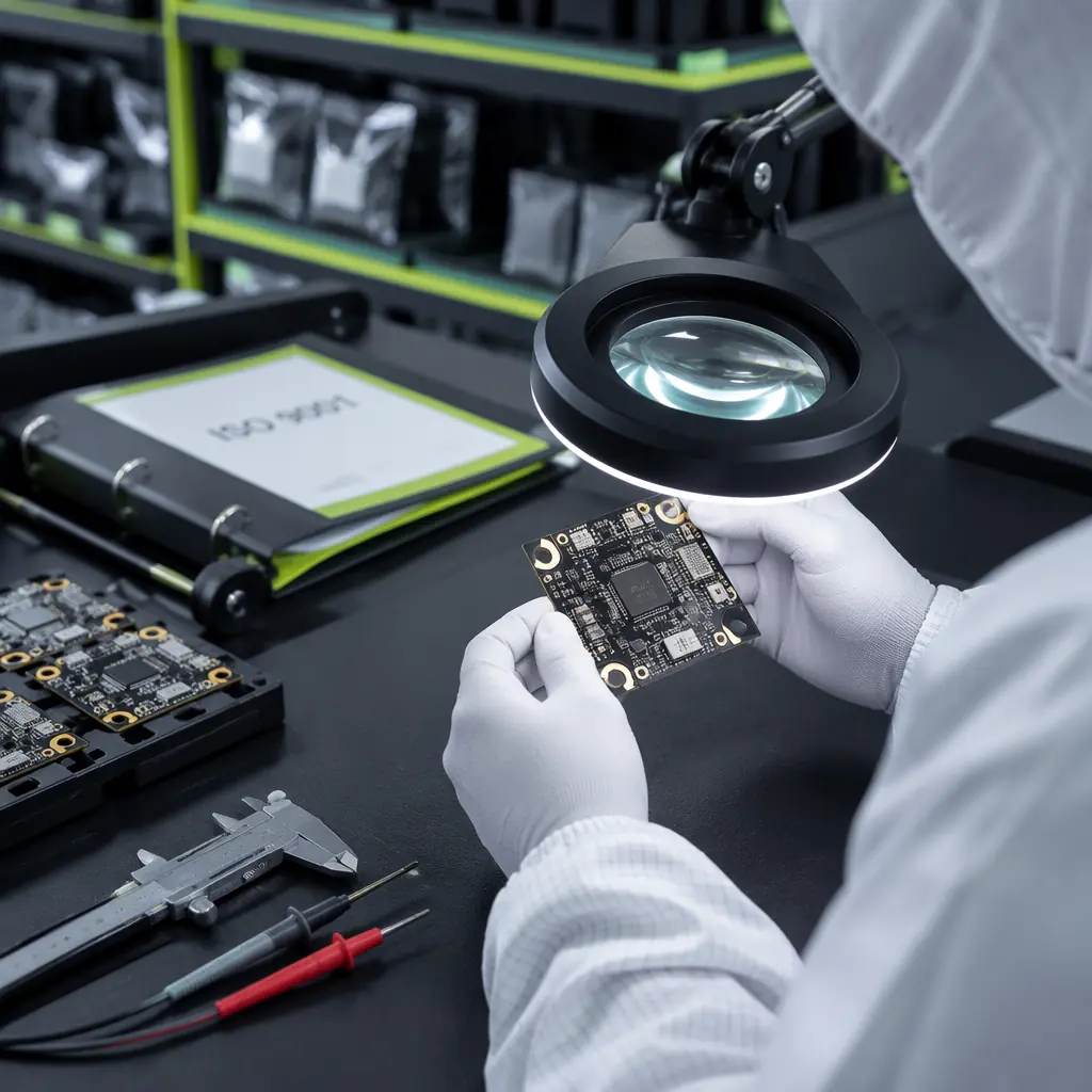
The audit script that turns the Class 3 criteria and the inspection layers into a factory-visit checklist — documentation, records, line observation and the red flags.
UAV Component Certification & Compliance
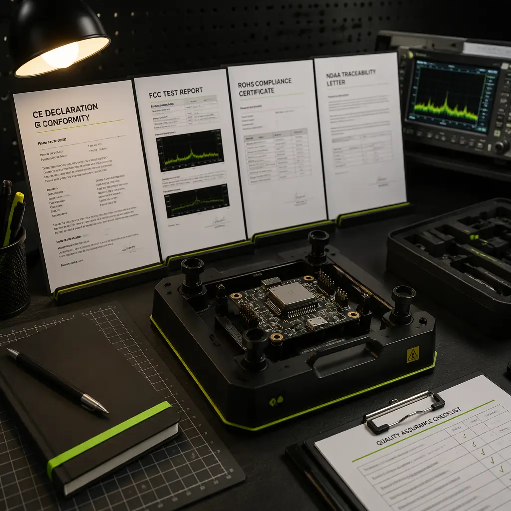
How the manufacturing evidence — the Class 3 records, the test reports, the traceability — fits into the CE, FCC, RoHS and airworthiness documentation package.
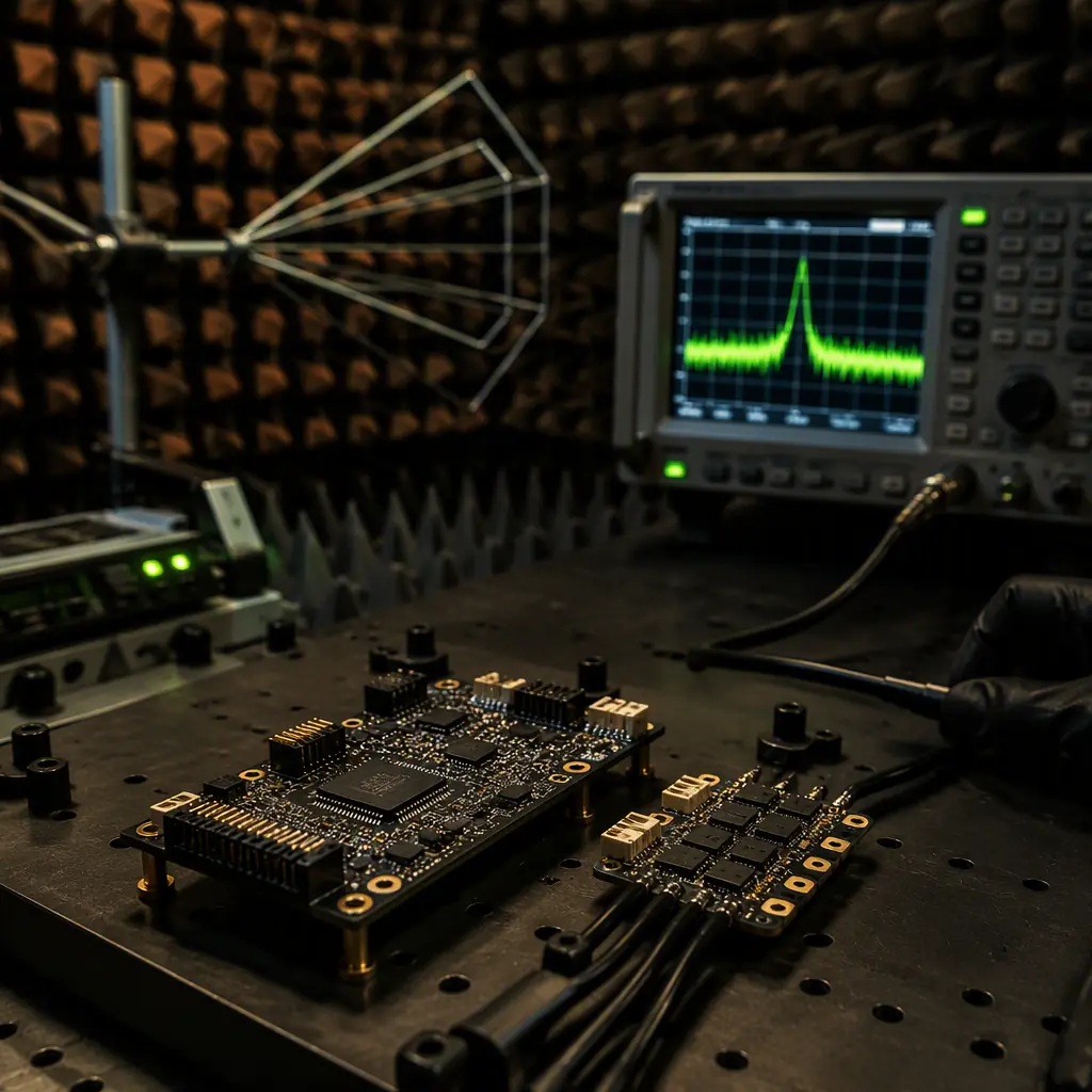
UAV Avionics EMC/EMI Design & Compliance
The PCB-level layout, shielding and manufacturing consistency that determine whether the emissions and immunity performance survives production.
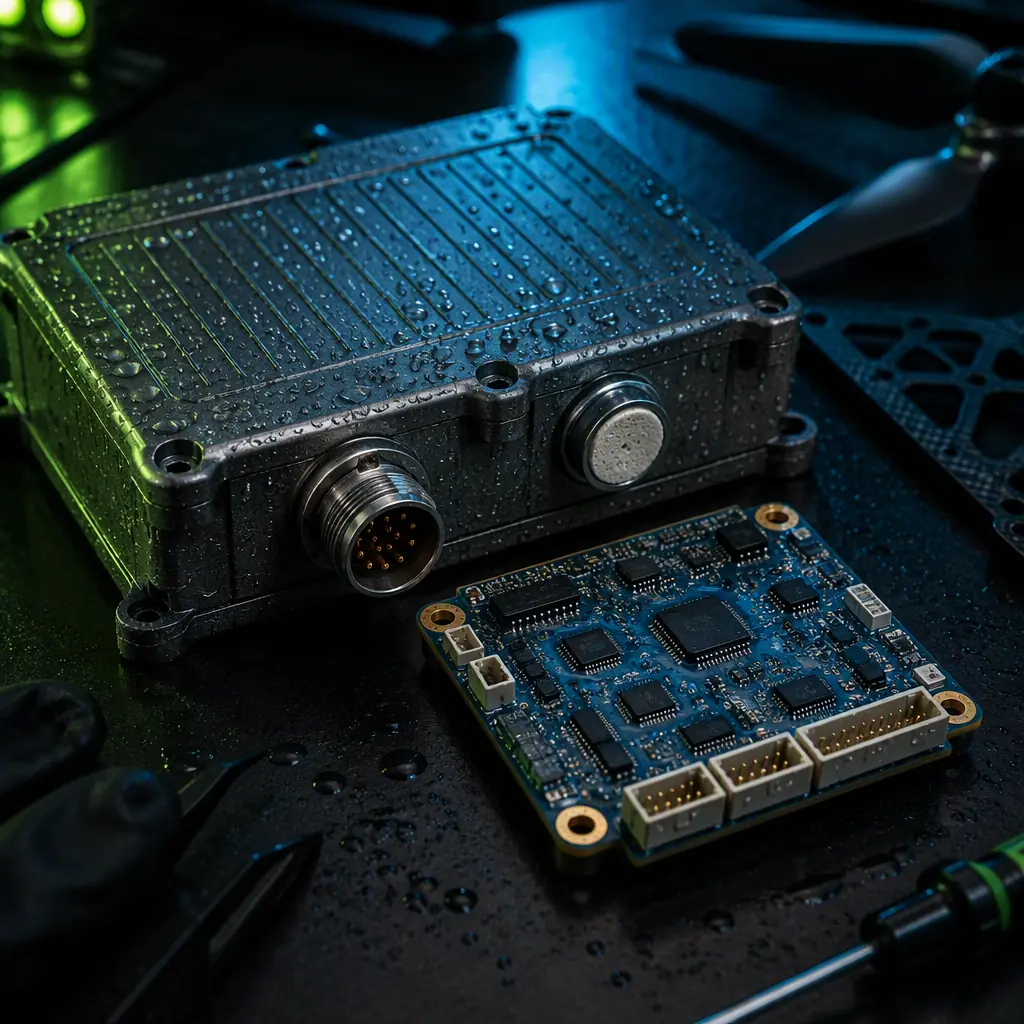
Waterproofing UAV Components: IP Ratings
The cleaning-before-coating sequence, the conformal coating specification and the contamination failures that the manufacturing process must prevent.

UAV Component Obsolescence Management
How lot traceability and the component date-code records interact with the lifecycle plan for long-lived UAV programs.