
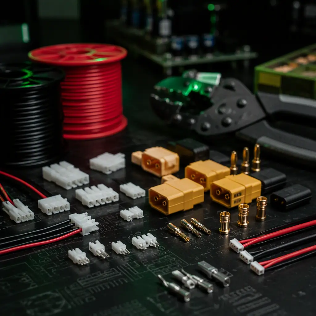
UAV electrical failures are dominated by connectors — a 2024 reliability study of 500 industrial UAV field failures across inspection, mapping and agricultural operations found that 34% of all electrical failures originated at a connector (a crimped terminal that backed out of its housing due to vibration, a soldered joint that cracked from thermal cycling, a pin that corroded from moisture ingress), compared to 22% from component failures (an ESC MOSFET that shorted, a voltage regulator that drifted out of specification), 18% from wiring (a chafed insulation that shorted to the carbon fiber airframe, a cold solder joint on a PDB pad), and 26% from other causes (battery cell imbalance, firmware faults, GPS interference). The connector failure rate is disproportionately high because a UAV has 40–80 connectors and each one is a single point of failure — when the flight controller's GPS UART connector disconnects, the EKF2 loses its position reference and the UAV enters a position-estimation failsafe within 1–2 seconds, potentially triggering an autonomous landing in unsuitable terrain. When the battery XT60 connector's spring contacts lose tension after 200 mating cycles and the contact resistance increases from 0.5 mΩ to 5 mΩ, the connector dissipates 10× more power as heat (I²R = 100 A² × 0.005 Ω = 50 W at peak current, enough to melt the nylon housing within 30 seconds) — and the voltage drop across the connector (100 A × 0.005 Ω = 0.5 V) reduces the voltage available to the ESCs by 2% on a 6S system, which reduces the maximum motor RPM and the UAV's climb rate. The procurement team's objective is to select connectors where the failure probability per connector per 100 flight hours is below 0.01% (one failure per 10,000 connector-flight-hours) — a reliability target that is achievable with correctly selected, correctly crimped and correctly strain-relieved connectors from the major manufacturers, and unachievable with generic clone connectors from an unqualified supplier.
For the matching of the flight controller to the ESCs that the connectors interface — the DShot 1200 protocol, the CAN FD bus and the PWM signal lines that the connectors carry — the flight controller and ESC matching guide covers the signal protocol requirements. For the propulsion system that the power connectors supply — the motor KV selection, the propeller matching and the thrust curve validation that determine the peak current the XT60/XT90 connector must carry — the UAV motor KV selection guide and the UAV propeller selection guide cover the electrical load definition. This article focuses on the interconnects themselves: the connector families, the wire selection, the PDB design and the harness reliability practices.
Signal connector families: JST GH, SH, ZH, PH and Molex PicoBlade compared
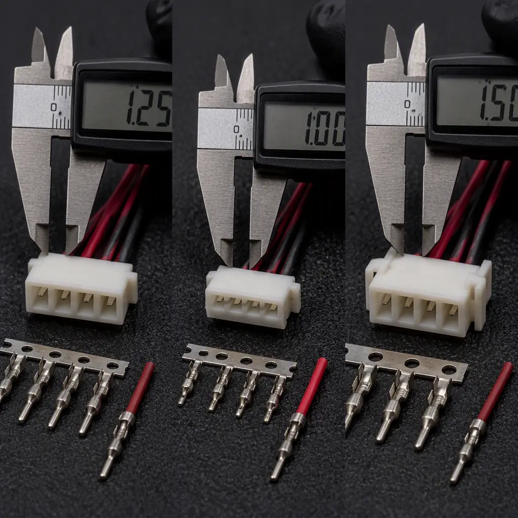
The flight controller's peripheral interfaces — UART (GPS, telemetry radio, companion computer, RC receiver), I²C (external compass, airspeed sensor, optical flow), SPI (external IMU, barometer), CAN (ESC telemetry, battery management system) and PWM (servo outputs, payload triggers) — all terminate in small-pitch board-to-wire connectors, and the procurement team's decision is which connector family to standardize on across the entire avionics stack. The two dominant families for UAV signal connectors are JST (particularly the GH, SH, ZH and PH series) and Molex (particularly the PicoBlade and PicoClasp series), and the selection criteria are: pitch (the centre-to-centre spacing between adjacent pins — 1.0 mm, 1.25 mm, 1.5 mm or 2.0 mm, which determines the connector's width on the PCB and the minimum wire gauge that can be terminated), current rating per contact (typically 1–3 A for signal connectors, determined by the contact surface area and the crimp terminal's cross-section), mating cycle rating (30–50 cycles for consumer-grade connectors, 100–500 cycles for industrial-grade — a UAV that is disassembled for maintenance every 50 flight hours will reach 100 mating cycles within 5,000 flight hours, so a 30-cycle connector rated for consumer electronics is the wrong procurement choice for an industrial UAV), and locking mechanism (a positive latch that prevents the connector from disconnecting under vibration vs a friction-fit that relies on the insertion force alone — the locking mechanism is the single most important procurement criterion for UAV connectors because vibration-induced disconnection is the most common failure mode).
 Concept illustration
JST GH (1.25 mm pitch, 1 A per contact, locking). The JST GH series is the de facto standard connector for Pixhawk and Cube flight controller peripherals — the GPS/Compass port (10-pin GH), the Telemetry 1 and Telemetry 2 ports (6-pin GH), the CAN 1 and CAN 2 ports (4-pin GH), the I²C port (4-pin GH) and the SPI port (6-pin GH) all use the GH 1.25 mm pitch connector with a positive locking latch that audibly clicks when fully seated. The GH's locking latch is critical — the connector can sustain 10–20 G of vibration (the typical vibration amplitude on a UAV motor mount is 5–15 G RMS from 50–500 Hz) without disconnecting, compared to a friction-fit connector of the same pitch that may disconnect at 3–5 G. The GH is rated for 30 mating cycles (JST's conservative rating; practical experience suggests 50–100 cycles before the latch retention force degrades noticeably) and accepts 28–32 AWG wire (0.08–0.32 mm², suitable for the 0.1–0.5 A signal currents on UAV peripherals). The procurement team should standardize on JST GH for all flight controller peripheral connections — a unified connector family simplifies the wiring harness BOM (one crimp tool, one terminal type, one housing family), reduces the procurement team's supplier count (JST GH terminals and housings are available from Digi-Key, Mouser, Arrow and most authorized distributors), and eliminates the risk of an engineer accidentally plugging a GPS into the wrong connector type.
JST SH (1.0 mm pitch, 1 A per contact, friction-fit). The JST SH is a 1.0 mm pitch connector commonly used on the Pixhawk's RC input port (the SBUS/PPM/DSM port, 3-pin SH) and on small peripheral boards (external compass modules, airspeed sensor breakout boards) where board space is at a premium. The SH's friction-fit retention (no locking latch — the connector is held in place by the insertion force of the crimp terminals against the header pins) makes it suitable only for connections that are assembled once and never disconnected during routine maintenance — the RC receiver connection, for example, is typically plugged in at the factory and remains connected for the UAV's service life, so the SH's lack of a locking latch is not a reliability concern. The SH is rated for 30 mating cycles and accepts 30–32 AWG wire. The procurement team should restrict SH connectors to permanent-connection applications (RC input, internal sensor modules that are never disconnected for maintenance) and use GH connectors for all field-serviceable connections.
JST ZH (1.5 mm pitch, 1 A per contact, friction-fit). The JST ZH is a 1.5 mm pitch connector commonly used for battery balance leads (the JST-XH balance connector on LiPo batteries is a ZH variant with a different keying — the ZH is the board-mount equivalent) and for low-current power connections to peripheral boards (3.3 V or 5 V power to a camera, a GNSS module or a telemetry radio at 0.5–2 A). The ZH's 1.5 mm pitch provides slightly more contact surface area than the GH, and the larger terminal accepts 26–30 AWG wire, making it suitable for 1–2 A power connections where a GH would be marginal. The ZH is friction-fit and should be secured with a dab of electronics-grade silicone adhesive (e.g., Dow Corning 3140 or equivalent) on the connector body after mating for vibration resistance — the adhesive prevents the connector from walking out under vibration but can be peeled off for maintenance.
Molex PicoBlade (1.25 mm pitch, 1 A per contact, friction-fit with latch option). The Molex PicoBlade 1.25 mm pitch connector is the primary competitor to the JST GH, offering a similar pitch and current rating but with a different terminal design (the PicoBlade terminal has a dual-beam contact that provides lower insertion force and higher vibration tolerance than the JST single-beam contact, according to Molex's application note). The PicoBlade's friction-fit housing can be replaced with a positive-latch housing (the PicoBlade 53398 series) that provides a locking mechanism comparable to the JST GH. The PicoBlade is rated for 30 mating cycles and accepts 28–32 AWG wire. The procurement choice between JST GH and Molex PicoBlade is largely an ecosystem decision: if the flight controller manufacturer standardizes on JST GH (as Pixhawk and Cube do), the procurement team should follow — mixing JST GH and Molex PicoBlade on the same UAV creates a wiring harness with two incompatible connector families, requiring two crimp tools, two terminal inventories and two housing inventories, increasing the procurement complexity and the risk of a technician using the wrong terminal for the wrong housing.
Power connectors: XT30, XT60, XT90, MR30 and Anderson Powerpole
UAV power connectors carry 15–150 A of DC current at 12–50 V and must satisfy three procurement criteria that signal connectors do not: ampacity (the continuous current rating at the UAV's maximum expected ambient temperature — typically +60°C in a sealed avionics bay on a summer day — derated by 20–30% from the manufacturer's 25°C rating to account for the elevated temperature, because connector contact resistance increases by approximately 0.4% per °C and the connector's ability to dissipate I²R heat decreases as the ambient temperature approaches the housing material's softening point), spark suppression (when a battery is connected to an ESC's input capacitors — typically 1,000–2,000 µF of low-ESR electrolytic capacitance — the inrush current can exceed 200 A for 1–5 milliseconds, vaporizing the connector contacts if the connector is not designed to withstand arcing on connection), and mechanical retention (the connector must not disconnect under 20 G of vibration or a 50 N pull force — a battery that ejects its XT60 connector during an aggressive climb or a hard landing loses all power to the propulsion system, and the UAV autorotates to the ground with no control authority).
 Concept illustration
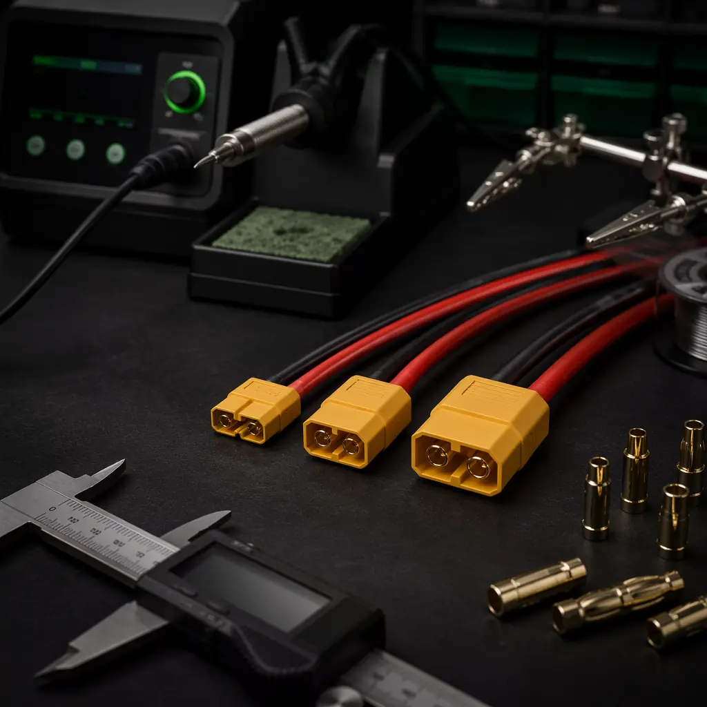
XT30 (30 A continuous, 2 mm gold-plated bullet, nylon housing). The XT30 is the standard power connector for small UAVs with a MTOW under 2 kg — a 4S 1,500 mAh battery powering four 2205-size motors with 20 A ESCs drawing a combined 40–60 A at full throttle, where the XT30's 30 A continuous rating (derated to 21–24 A at +60°C ambient) is sufficient because full throttle is a transient condition lasting 5–15 seconds on a typical flight, and the connector's short-term overload capacity (45 A for 30 seconds) covers the peak. The XT30's 2 mm gold-plated bullet contacts provide 0.5–1.0 mΩ of contact resistance (measured by the voltage drop across the connector at 10 A DC, divided by 10 A — typically 5–10 mV, confirming 0.5–1.0 mΩ), dissipating 0.5–1.0 W of heat at 30 A — acceptable for a connector in open air but requiring ventilation if the connector is enclosed in a sealed avionics bay. The XT30's nylon housing is rated for 120°C continuous — well above the connector's normal operating temperature of 40–60°C at 30 A, but the housing will soften and deform if the contact resistance increases to 10 mΩ due to a worn gold plating (dissipating 9 W at 30 A, raising the connector temperature above 120°C within 60 seconds), which is why the connector should be replaced after 200–500 mating cycles — the gold plating wears through to the nickel underplate, and the nickel-on-nickel contact resistance is 5–10× higher than gold-on-gold.
XT60 (60 A continuous, 3.5 mm gold-plated bullet, nylon housing). The XT60 is the standard power connector for medium UAVs with a MTOW of 3–10 kg — a 6S 12,000–22,000 mAh battery powering four to six 400–600 KV motors drawing a combined 60–120 A at full throttle, where the XT60's 60 A continuous rating (derated to 42–48 A at +60°C) is marginal for the peak current. The XT60's procurement decision is: if the UAV's sustained current (the current draw during a 30-second full-throttle climb, measured on a thrust stand with the production propellers and battery at 50% state of charge — this is a procurement specification, not an engineering estimate) exceeds 48 A (the derated continuous rating at +60°C), upgrade to the XT90. The XT60 can carry 80–90 A for 30–60 seconds without damage — the gold-plated contacts and the nylon housing have sufficient thermal mass to absorb the I²R heat for a short duration — but sustained operation above the derated continuous rating will cause the connector temperature to rise above the housing's softening point, leading to contact misalignment and a runaway increase in contact resistance (the contact resistance increases with temperature, which increases the I²R heating, which increases the temperature — a positive feedback loop that melts the connector within 2–5 minutes at 20–30 A above the rated current).
XT90 (90 A continuous, 4.5 mm gold-plated bullet, nylon housing with anti-spark resistor option). The XT90 is the power connector for large UAVs with a MTOW above 10 kg — a 12S 22,000–44,000 mAh battery powering six to eight 100–200 KV motors drawing a combined 120–200 A at full throttle, where the XT90's 90 A continuous rating (derated to 63–72 A at +60°C) is sufficient for most industrial UAVs but requires an anti-spark variant (XT90-S) to prevent the inrush current from vaporizing the connector contacts. The XT90-S incorporates a 5.6 Ω resistor in the positive bullet that makes contact before the main gold-plated contact, pre-charging the ESC's input capacitors through the resistor at a controlled current (V/R = 50 V / 5.6 Ω = 8.9 A for a 12S system, well within the connector's rating) over approximately 10–20 milliseconds (the RC time constant of 5.6 Ω × 2,000 µF = 11.2 ms), after which the main contact engages with a negligible voltage difference across the connector and no arcing. The XT90-S adds approximately $0.50 to the connector cost and eliminates the most common failure mode of large-UAV power connectors — a connector that develops pitting and carbon tracking on the gold-plated contacts from repeated arcing during battery connection, increasing the contact resistance from 0.5 mΩ to 5–10 mΩ after 50–100 cycles and eventually melting the housing during a high-current manoeuvre.
MR30 (30 A per contact, 3-pin, gold-plated, locking ring). The MR30 is a 3-pin circular connector rated at 30 A per pin, designed for the brushless motor phase wires — the three wires from the ESC to the motor (U, V, W phases) that carry the sinusoidal PWM current at the ESC's switching frequency (24–48 kHz) and the motor's electrical commutation frequency (50–500 Hz for a 12N14P motor at 3,000–30,000 RPM). The MR30's key procurement advantage over the traditional 3.5 mm bullet connector is the integrated locking ring — a threaded collar that prevents the connector from disconnecting under vibration, which is the most common failure mode of motor bullet connectors (a bullet connector that vibrates apart mid-flight causes a single-phase open circuit, and the motor — now running on two phases — produces zero torque at certain rotor angles, vibrates violently and may damage the motor bearings, the propeller and the motor mount within 5–10 seconds). The MR30 adds approximately 5 grams per connector (vs 3 grams for three individual 3.5 mm bullets) and costs $3–5 per set (vs $1–2 for three bullets), but the locking ring eliminates the bullet connector's single-point-of-failure reliability risk. For a UAV operating BVLOS at 10 km from the operator — where a motor phase disconnection results in a forced landing in unknown terrain — the MR30's $3 premium is negligible compared to the cost of a crashed airframe ($2,000–$15,000) and a lost mission ($5,000–$50,000 in operational downtime and re-fly costs).
Anderson Powerpole (15/30/45 A, genderless, stackable). The Anderson Powerpole PP15/PP30/PP45 series is a genderless, stackable power connector commonly used in ground control stations, battery charging setups and test bench power distribution — but rarely on the UAV airframe itself because the Powerpole's large size (25×15×10 mm for the PP30, compared to 15×10×7 mm for the XT30) and unsealed design (the contacts are exposed to moisture and debris) make it unsuitable for flight use. The Powerpole is the correct procurement choice for the ground-side equipment: the battery charger output, the ground control station power input, and the test bench power supply — applications where the genderless design (any Powerpole can connect to any Powerpole of the same series) simplifies the cabling and the stackable housing (multiple Powerpoles can be dovetailed together to create a multi-pole connector for power + ground + signal) reduces the connector count.
Wire gauge selection: AWG, insulation type and current capacity in a UAV context
The wire gauge (AWG — American Wire Gauge) determines the conductor's cross-sectional area, its DC resistance per metre, its current-carrying capacity and its weight — and the procurement team's decision is the minimum AWG that safely carries the circuit's maximum expected current without exceeding the insulation's temperature rating, because every unnecessary AWG step (e.g., 12 AWG instead of 14 AWG for a motor phase wire) adds 25–50% to the wire's weight (copper weighs 8.96 g/cm³ — a 1-metre length of 14 AWG silicone wire weighs 12 grams, while a 1-metre length of 12 AWG weighs 19 grams) and 30–60% to the wire's cost. On a UAV with 4–8 motor phase wires, each 30–60 cm long, the wire weight across all phase wires is 30–100 grams for 14 AWG and 50–170 grams for 12 AWG — a difference of 20–70 grams that directly reduces the payload budget.
AWG ampacity for UAV applications. The standard ampacity tables (e.g., the NEC 310.16 table for building wiring) are conservative for UAV applications because UAV wiring is in open air (better convection cooling than a conduit or a cable tray), the wire runs are short (30–60 cm, compared to 10–100 m for building wiring, so the voltage drop is proportionally smaller), and the current is intermittent (the full-throttle current flows for 5–30 seconds during takeoff and climb, followed by 5–15 minutes of cruise at 40–60% throttle where the current is 30–50% of the full-throttle value). The following ampacity values are appropriate for UAV applications with silicone-insulated wire (rated for 200°C) in free air at 25°C ambient, derated by 20% for operation in a sealed avionics bay at +60°C ambient:
- 22 AWG (0.33 mm²) — 5 A continuous, 8 A peak (30 seconds). Signal wiring: GPS, telemetry radio, RC receiver, I²C sensors, companion computer serial link. Weight: 3 g/m.
- 20 AWG (0.52 mm²) — 8 A continuous, 12 A peak. Servo power, camera power, gimbal power, payload trigger. Weight: 5 g/m.
- 18 AWG (0.82 mm²) — 12 A continuous, 18 A peak. Small ESC power input (20 A ESC), LED lighting, video transmitter power. Weight: 8 g/m.
- 16 AWG (1.31 mm²) — 18 A continuous, 25 A peak. Medium ESC power input (30 A ESC), BEC output to flight controller and servos. Weight: 12 g/m.
- 14 AWG (2.08 mm²) — 30 A continuous, 45 A peak. Large ESC power input (40–50 A ESC), battery-to-PDB main power (for UAVs drawing < 60 A total). Weight: 19 g/m.
- 12 AWG (3.31 mm²) — 45 A continuous, 65 A peak. Motor phase wires (40–60 A per motor), PDB-to-ESC power (for UAVs drawing 60–100 A total). Weight: 30 g/m.
- 10 AWG (5.26 mm²) — 65 A continuous, 90 A peak. Battery-to-PDB main power for large UAVs (100–150 A total), high-current PDB bus bars. Weight: 47 g/m.
Insulation type — silicone vs PVC. UAV wiring universally uses silicone-insulated wire (not PVC-insulated wire) for three procurement-critical reasons: (1) silicone insulation is rated for 200°C continuous (vs 105°C for PVC), so a wire that carries 45 A and operates at 80–100°C (well within the silicone rating) would exceed the PVC rating at the same current; (2) silicone remains flexible at −60°C (vs PVC, which stiffens and cracks below −10°C), which is critical for UAVs operating in cold climates where a PVC-insulated wire that flexes during flight at −20°C may develop insulation cracks that expose the conductor to moisture and cause an electrical short; and (3) silicone insulation strips cleanly without melting or deforming (PVC insulation melts and retracts when soldered at 350°C, exposing 2–5 mm of bare conductor beyond the intended strip length and increasing the risk of a short circuit to an adjacent connector pin or the carbon fiber airframe). Silicone wire costs approximately 2–3× more than PVC per metre ($0.50–$2/m for silicone vs $0.20–$0.80/m for PVC in small quantities) — a negligible cost difference on a UAV with 10–20 metres of total wiring ($10–$40 total) compared to the cost of a single PVC insulation failure that causes a crash.
Wire colour coding standard. A standardized wire colour code across the UAV's wiring harness reduces assembly errors (a technician connecting a black ground wire to a red power input because the colour code was inconsistent between the flight controller and the PDB) and simplifies field troubleshooting. The recommended UAV wire colour standard, adapted from the IPC/WHMA-A-620 aerospace wiring standard: red = battery positive (Vbat, 12–50 V), black = battery ground (GND), orange = regulated power (5 V or 3.3 V from a BEC or voltage regulator), yellow or white = signal (UART TX/RX, I²C SDA/SCL, SPI MOSI/MISO, PWM output), blue = motor phase (U phase, or use three distinct colours — red/black/blue or yellow/green/blue — for the three motor phases), green = CAN bus (CAN H and CAN L with a twisted pair). The procurement team should specify the wire colour code in the wiring harness assembly drawing and verify that the harness supplier follows it — a harness with inconsistent colours costs $2,000–$5,000 to rework (stripping and re-crimping every incorrectly coloured wire) vs $0 in additional material cost to use the correct colour from the start.
Power distribution board design: copper weight, trace width and thermal management
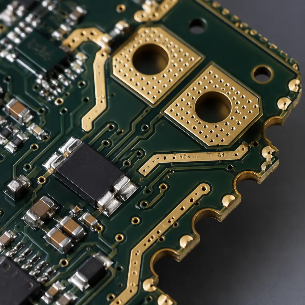
The power distribution board (PDB) routes the battery voltage to each ESC, the flight controller's power module, the companion computer's DC-DC converter and any auxiliary loads (gimbal, camera, lighting, payload release mechanism). The PDB is a custom PCB — typically a 2- or 4-layer board, 1.6 mm thick, with 2 oz (70 µm) or 4 oz (140 µm) copper on the power layers to carry the total system current (40–200 A) without excessive voltage drop or temperature rise. The procurement team specifies the PDB's copper weight and the minimum trace width for the highest-current path (the battery input to the first distribution node, which carries the full system current), and the PCB manufacturer fabricates the board to that specification — if the specification is wrong, the PDB's traces overheat and delaminate from the FR-4 substrate, creating an open circuit in the power distribution network that disables all downstream ESCs simultaneously (a total power loss event).
 Concept illustration
Copper weight selection. Standard PCB copper weights are 1 oz (35 µm), 2 oz (70 µm) and 4 oz (140 µm) — the number refers to the weight of copper per square foot of board area. For a UAV PDB carrying 40–200 A total, the copper weight selection rule is: 1 oz is insufficient for any PDB carrying more than 10 A total (a 10 mm wide, 1 oz trace can carry approximately 8–10 A with a 20°C temperature rise — too narrow for a 40 A PDB); 2 oz is sufficient for PDBs carrying 10–60 A (a 15 mm wide, 2 oz trace can carry approximately 30–35 A, and multiple parallel traces or a copper pour can distribute the current across the board); 4 oz is required for PDBs carrying 60–200 A (a 20 mm wide, 4 oz trace can carry approximately 60–70 A, and the entire power layer becomes a copper pour that distributes the current with negligible voltage drop). The procurement specification for the PDB's copper weight is: "4 oz (140 µm) copper on all power layers, with a minimum trace width of 20 mm for the battery input to distribution node path, verified by the PCB manufacturer's cross-section micrograph." The cross-section micrograph requirement ensures that the PCB manufacturer actually deposited 4 oz of copper, not 3.5 oz (which can happen if the manufacturer reuses a plating bath that is depleted — the difference between 3.5 oz and 4 oz is a 12.5% reduction in current-carrying capacity, which may push a 60 A PDB trace into thermal runaway at +60°C ambient).
Thermal relief and via stitching. The PDB's power traces and copper pours must include thermal relief connections to the ESC output pads — a spoke pattern that reduces the thermal conductivity between the pad and the copper pour, allowing the pad to be soldered at 350°C without the copper pour sinking the heat and making the solder joint cold (a cold solder joint on an ESC power pad has a resistance of 5–50 mΩ instead of the expected 0.1–0.5 mΩ, dissipating 10–100× more heat and potentially desoldering itself during a high-current manoeuvre — a failure mode where the ESC loses power mid-flight and the motor stops instantaneously, causing the UAV to yaw violently and potentially enter an unrecoverable spin). The thermal relief spoke width should be 0.3–0.5 mm for a 2 oz copper pour and 0.5–0.8 mm for a 4 oz copper pour — wide enough to carry the pad's current without fusing, narrow enough to allow the pad to reach soldering temperature. Additionally, the PDB should use via stitching (a grid of plated through-holes connecting the top and bottom copper pours) to distribute current between layers and to provide thermal vias under high-current components (the current sense resistor, the power MOSFETs on an integrated PDB) that conduct heat from the component's thermal pad to the bottom copper pour, which can dissipate heat to the airframe through a thermal pad or a heatsink.
PDB vs wiring harness — the procurement trade-off. A custom PDB (a single PCB that distributes power to all ESCs and peripherals) costs $5–15 per board in quantities of 100–500 and weighs 20–50 grams. A wiring harness (individual wires from a central solder joint or a power distribution block to each ESC) costs $2–5 in materials but requires 30–60 minutes of skilled assembly labour ($15–$30 at a loaded labour rate of $30/hour), weighs 30–80 grams (the solder joint and the wire branches add weight compared to a PCB's copper traces) and has 10–20 solder joints — each one a potential failure point. The PDB is the correct procurement choice for any UAV programme producing more than 50 units, because the PDB's unit cost is lower when the assembly labour is included, the reliability is higher (a PCB trace does not fatigue or crack from vibration, while a solder joint in a wiring harness does — particularly if the solder wicks up the wire strands, creating a rigid section that concentrates the bending stress at the solder-wire interface), and the consistency is better (every PDB is identical; every wiring harness is slightly different depending on the technician's technique). The wiring harness is the correct choice for prototyping and very low-volume production (1–10 units), where the PDB's NRE cost ($500–$2,000 for the PCB design, fabrication and assembly setup) exceeds the wiring harness's labour cost. For the build-vs-buy decision framework that applies the same logic to the entire UAV subsystem — the UAV component build vs buy guide covers the total cost of ownership calculation that determines whether a custom PDB or an off-the-shelf PDB is the lower-cost option over the programme's life.
EMI and signal integrity: shielding, twisting and separation for UAV wiring
The UAV's electrical environment is hostile to signal integrity: the four to eight brushless motors draw 20–50 A of PWM-modulated current at 24–48 kHz, with dI/dt slew rates of 50–200 A/µs (the MOSFETs switch in 50–200 nanoseconds, and the current transitions from 0 to 50 A within that switching time), radiating a magnetic field that couples into adjacent signal wires through mutual inductance. A GPS UART signal wire that runs parallel to a motor phase wire for 10 cm at a separation distance of 5 mm will experience a common-mode noise voltage of approximately 50–200 mV peak-to-peak — enough to corrupt the UART data (the STM32H7's UART receiver has a noise margin of approximately 200–300 mV for a 3.3 V logic level, so a 200 mV noise spike superimposed on the UART signal can cause a bit error that corrupts a MAVLink packet, requiring the flight controller to discard the packet and request a retransmission, adding 10–20 ms of latency to the GPS position update). The procurement team's EMI mitigation strategy has three layers, applied in order of cost and effectiveness.
Layer 1 — physical separation. The most effective EMI mitigation costs $0 and adds 0 grams: route the signal wires at least 20 mm away from the motor phase wires and the ESC power wires, and cross them at 90° when they must intersect (a perpendicular crossing minimizes the mutual inductance — the magnetic field lines from the motor wire are parallel to the motor wire's axis, and a signal wire that crosses perpendicularly captures near-zero magnetic flux). The procurement team should specify the wire routing in the wiring harness assembly drawing — a diagram that shows the physical path of every wire bundle through the airframe, with the signal bundle (GPS, telemetry, I²C, SPI, CAN — all low-current, noise-sensitive signals) routed along the top of the avionics bay (as far as possible from the motor wires, which enter the avionics bay from the arms at the sides and bottom) and the power bundle (battery, PDB, ESC power — all high-current, noise-generating conductors) routed along the bottom.
Layer 2 — twisted pair for differential signals. CAN bus, I²C (with an active terminator) and some UART implementations (RS-422) use differential signalling — the data is transmitted as the voltage difference between two wires (CAN H and CAN L), and any common-mode noise (the same noise voltage induced on both wires by a nearby motor phase wire) is rejected by the differential receiver (the CAN transceiver's common-mode rejection ratio is typically 40–60 dB, attenuating the common-mode noise by a factor of 100–1,000). Twisting the differential pair (one twist per 10–20 mm — approximately 5–10 twists per 10 cm) ensures that both wires capture the same magnetic flux from the noise source, maximizing the common-mode rejection. The procurement team should specify twisted pair for all CAN bus and I²C connections and should use pre-twisted wire (available from TE Connectivity, Alpha Wire and other wire manufacturers — a red/black twisted pair of 26 AWG, for example) rather than relying on the harness assembler to twist the wires manually (manual twisting is inconsistent — the twist pitch varies, and an uneven twist pitch reduces the common-mode rejection by 10–20 dB).
Layer 3 — shielding. For signals that cannot tolerate any noise — the GPS UART (a single-ended signal with no common-mode rejection), the video downlink coax (which carries a 5.8 GHz analog video signal that is directly modulated by any noise on the ground shield), and the companion computer's USB 3.0 link (which operates at 5 Gbps and has a signal-to-noise ratio requirement of > 20 dB) — a shielded cable is required. The shield is a braided copper sleeve or an aluminum foil wrap that surrounds the signal conductor, connected to ground at one end only (the flight controller end for a GPS UART cable — connecting the shield at both ends creates a ground loop, as described in the companion computer integration section). The shield attenuates the magnetic field by inducing an opposing current (Lenz's law) that cancels the incident field — a braided copper shield with 85% coverage provides approximately 20–30 dB of magnetic field attenuation at 24–48 kHz (the ESC's switching frequency), reducing the induced noise voltage by a factor of 10–30. The procurement team should specify shielded cables for the GPS UART (a 4-conductor shielded cable: VCC, GND, TX, RX, with the shield connected to GND at the flight controller end), the telemetry radio UART (same specification), the video transmitter coax (RG-178 or equivalent, 50 Ω impedance, SMA or u.FL connector) and any USB 3.0 connection that runs within 50 mm of a motor phase wire. For the communication protocols and RF systems that the shielded cables serve — the UAV RF communication systems guide covers the antenna matching, the coax cable loss and the interference management for 433 MHz, 868/915 MHz and 2.4 GHz data links.
Connector reliability: vibration, thermal cycling, mating cycles and environmental sealing
The procurement team's connector reliability specification must address four degradation mechanisms, each of which can cause a connector to fail within the UAV's operational life (typically 500–2,000 flight hours over 3–5 years).
Vibration. The UAV's motors generate broadband random vibration from 50–500 Hz at 0.02–0.05 g²/Hz (the MIL-STD-810G helicopter vibration profile, which the UAV's motor vibration approximates), and a connector that is not positively locked will fret — the contact surfaces rub against each other at the vibration frequency, wearing through the gold plating within 10–50 flight hours and exposing the nickel underplate (which oxidizes, increasing the contact resistance by 10–50×). The procurement specification for vibration resistance is: every connector on the UAV, including signal connectors, must have a positive locking mechanism (a latch, a locking ring, a screw lock or a bayonet lock) that prevents relative motion between the male and female contacts under the UAV's operational vibration profile. Friction-fit connectors (JST SH, ZH, PH; Molex PicoBlade without the latch variant) are acceptable only for connections that are strain-relieved (the wire is secured to the airframe with a cable tie or an adhesive pad within 20 mm of the connector, so the vibration force is absorbed by the wire's strain relief, not by the connector contacts) and that are not disconnected during routine maintenance (so the gold plating's wear from mating/unmating does not combine with the vibration fretting).
Thermal cycling. The UAV's avionics bay temperature cycles from −20°C (cold soak before a winter dawn flight) to +60°C (full-power operation in direct sunlight on a summer afternoon) — an 80°C temperature swing that occurs once or twice per flight, accumulating 500–2,000 cycles over the UAV's operational life. The connector's metal contacts and plastic housing have different coefficients of thermal expansion (CTE) — the gold-plated brass contact expands at 18–20 ppm/°C, while the nylon housing expands at 50–80 ppm/°C — so a temperature increase of 80°C causes the housing to expand 0.4–0.6% more than the contact, creating a gap between the contact and the housing that allows the contact to shift within the housing. Over 500–2,000 thermal cycles, the contact's retention force (the force required to push the contact out of the housing) decreases by 20–50%, and a contact that loses retention may back out of the housing during the next maintenance cycle, creating an intermittent connection that is difficult to diagnose (the UAV passes the pre-flight check because the contact is still partially seated, then disconnects mid-flight from vibration). The procurement mitigation for thermal cycling is: select connectors from manufacturers who publish a thermal cycling test report (JST, Molex, TE Connectivity, Amphenol — the major connector manufacturers test their connectors to 500–1,000 thermal cycles from −40°C to +85°C and provide the contact retention force before and after cycling), and derate the manufacturer's mating cycle rating by 50% for UAV applications (a 30-cycle connector is replaced after 15 maintenance cycles).
Environmental sealing. A UAV operating in rain, fog, coastal salt spray or agricultural chemical spray will expose its connectors to moisture, and a connector that is not environmentally sealed will develop corrosion on the gold-plated contacts (gold does not corrode, but the nickel underplate does — and once the gold plating is worn through at a microscopic scratch, the nickel oxidizes and the contact resistance increases by 10–100× within 10–50 flight hours of moisture exposure). The procurement specification for environmental sealing is: connectors exposed to the external environment (the GPS and telemetry antenna connectors on the top of the airframe, the payload connector on the underside) must be IP67 rated (dust-tight and protected against immersion in 1 metre of water for 30 minutes — achieved with a silicone O-ring in the connector housing or with a dielectric grease-filled boot). Connectors inside the avionics bay (the flight controller peripherals, the PDB connections, the companion computer interface) should be protected by a conformal coating (a 25–50 µm layer of acrylic, silicone or urethane coating applied to the assembled PCB after the connectors are mated — the coating seals the connector-to-PCB interface and prevents moisture from wicking into the connector through capillary action along the PCB surface) and by a desiccant pack inside the avionics bay (a 5–10 gram silica gel pack that absorbs the moisture that enters the avionics bay when the UAV transitions from a cold, high-humidity environment at altitude to a warm, humid environment at ground level — the temperature drop causes condensation on the avionics, and the desiccant absorbs it before it reaches the connectors).
Connector procurement checklist
The following checklist translates the connector selection framework into actionable procurement items that a UAV programme manager can implement during the design phase.
Connector family standardization (design phase, week 1). Select a single connector family for all flight controller peripheral connections — JST GH (1.25 mm pitch, locking) for all UART, I²C, SPI and CAN peripherals. Select a single power connector family — XT30 for UAVs under 2 kg, XT60 for UAVs 3–10 kg, XT90-S (anti-spark) for UAVs above 10 kg. Select MR30 connectors for all motor phase connections if the UAV operates BVLOS or in inaccessible terrain. Document the connector selection in the BOM with the manufacturer part number, the authorized distributor and the alternate source (a second authorized distributor for supply chain resilience — if Digi-Key is out of stock on JST GH 6-pin housings, Mouser or Arrow should have them, and the BOM should list all three distributor part numbers). The deliverable is a connector selection BOM with the manufacturer part number, the distributor part number(s) and the unit cost at the programme's expected production volume.
Crimping tool and terminal specification (design phase, week 2). Specify the crimping tool for each connector family — the JST WC-240 for GH terminals ($300–500, or the Engineer PA-09 generic crimper at $40 for low-volume production), the Anderson Powerpole crimper for PP15/PP30/PP45 terminals ($50–150). The crimping tool is a procurement item, not an engineering tool — it must be included in the production BOM and the assembly work instructions. The procurement team should also specify the crimp terminal pull-test requirement: every crimped terminal must withstand a pull force of at least 10 N (for 28–32 AWG signal wires) or 30 N (for 14–18 AWG power wires) without the wire pulling out of the terminal — a pass/fail test that takes 5 seconds per terminal and costs $200–500 for a digital force gauge (e.g., the Mark-10 Series 3). The deliverable is the crimping tool part number and the pull-test force specification in the assembly work instructions.
Wire gauge and insulation specification (design phase, week 3). Calculate the maximum expected current for each circuit (motor phase, ESC power, battery main, flight controller power, peripheral power) using the thrust stand measurement at full throttle with the production propellers and battery at 50% state of charge. Select the wire gauge per the ampacity table above, with a 20% derating for +60°C ambient operation. Specify silicone-insulated wire (not PVC) for all UAV wiring. Specify the wire colour code standard in the wiring harness assembly drawing. The deliverable is a wire specification table with the circuit name, the maximum current, the selected AWG, the insulation type and the colour code.
PDB specification (design phase, week 4). Specify the PDB's copper weight (2 oz for 10–60 A total, 4 oz for 60–200 A total), the minimum trace width for the battery input path (20 mm for 4 oz copper, 15 mm for 2 oz copper), the thermal relief spoke width (0.3–0.5 mm for 2 oz, 0.5–0.8 mm for 4 oz) and the via stitching pattern (0.3–0.5 mm diameter vias on a 1–2 mm grid under high-current components). Verify the PDB specification with the PCB manufacturer before placing the fabrication order — a 10-minute call with the manufacturer's applications engineer can prevent a PDB that delaminates on the first flight. For the supplier evaluation criteria that determine whether a PCB manufacturer can reliably produce 4 oz copper boards with the specified thermal relief — the UAV supplier evaluation checklist covers the PCB manufacturer audit criteria, the quality certifications (IPC-A-600 Class 2 or 3) and the cross-section micrograph requirement.
EMI validation (integration phase, week 5). After the wiring harness is assembled and installed in the airframe, verify the EMI performance: connect an oscilloscope to the GPS UART RX line (probe the signal at the flight controller's UART input pin — not at the GPS module's output, because the noise is induced along the cable and the worst-case noise is at the receiver end), power the motors to 50% throttle (enough to generate the PWM current that produces the EMI, without requiring the UAV to be airborne), and measure the peak-to-peak noise voltage on the UART line. If the noise exceeds 200 mV peak-to-peak, add shielding, increase the separation between the signal wire and the motor phase wires, or add a ferrite bead (a Fair-Rite 0443164251 or equivalent, 260 Ω at 100 MHz — the bead's impedance at 24–48 kHz is 5–20 Ω, enough to attenuate the PWM noise by 6–12 dB when placed within 20 mm of the flight controller's UART input pin). The deliverable is an EMI validation report with the peak-to-peak noise voltage on each signal line at 50% throttle, with a PASS/FAIL threshold of 200 mV. For the testing and validation framework that covers the full UAV system-level acceptance test — the UAV propulsion testing and validation guide covers the test protocols that apply to any electrical subsystem.
Explore custom engineering Back to Blog
Continue Reading
UAV Motor KV Selection Guide
How to calculate the motor's electrical load — the current draw at full throttle that determines whether the XT60 or XT90 connector is sufficient and whether the 14 AWG or 12 AWG motor phase wire is required.
UAV Battery & Power Management
The battery-to-PDB interface — LiPo vs Li-Ion connector requirements, the spark suppression circuit and the power budget allocation that defines the maximum current the XT60/XT90 must carry.
UAV Thermal Management
How the PDB's copper traces dissipate heat in a sealed avionics bay at +60°C ambient — and the thermal derating curves that determine whether a 4 oz copper PDB trace rated for 60 A at 25°C can carry 45 A at +60°C without delaminating.
UAV Supplier Evaluation Checklist
How to audit a connector supplier — the IPC/WHMA-A-620 crimp quality requirements, the counterfeit connector detection (clone XT60 connectors with steel contacts plated to look like gold are common on Alibaba), and the lot traceability standard.
UAV Propulsion Testing & Validation
The system-level electrical test — measuring the voltage drop across every connector in the power path at full throttle, verifying that no connector exceeds a 50 mV drop (which would indicate > 1 mΩ of contact resistance and a potential thermal failure).