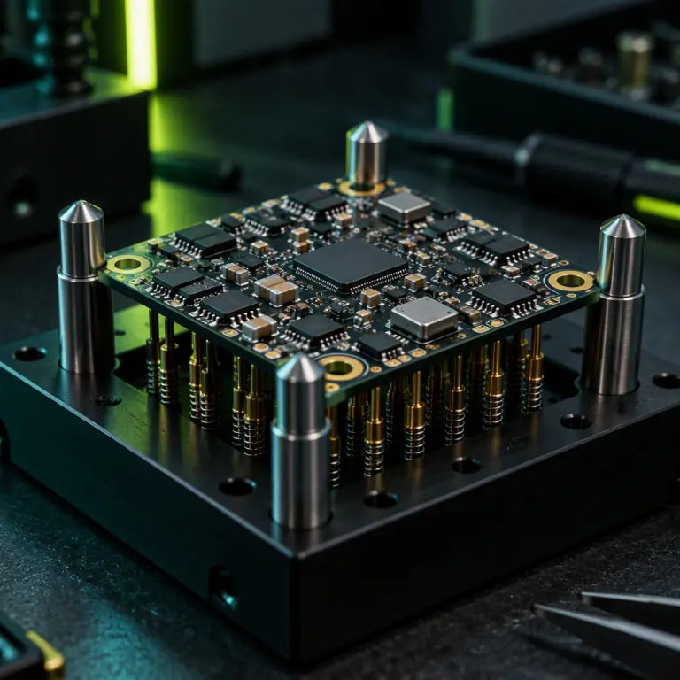
The conversation about UAV reliability usually happens at the wrong level. Buyers interrogate the component specification, the firmware version, the certification paperwork, and then accept whatever test evidence the supplier attaches to the shipment. That evidence is the output of a manufacturing test line, and it is only worth what the fixtures on that line are worth. A test report that says 100% pass tells you nothing unless you know what the station measured, how tightly it measured it, and whether the measurement could actually distinguish a good unit from a marginal one.
This is not a hypothetical risk in UAV work, because the failure modes that matter most are marginal ones. A flight controller that passes a power-on test and then drifts its gyro bias past the arming threshold at 40 °C ambient, an ESC that commutates cleanly on a bench motor and desynchronises at 92% throttle under load, a radio module with a receive sensitivity 3 dB worse than the datasheet because a matching component was placed 1.5 mm off nominal. None of those are visible to a continuity check. All three are visible to a fixture that was specified with the failure mode in mind. The examination of IPC-A-610 and J-STD-001 workmanship covers what the assembly must look like; this guide covers what it must measure.
Where production test sits, and what each stage can prove
Production test is not one event. It is a sequence of stages, each with a specific and bounded claim, and the classic mistake is to ask a cheap stage to answer an expensive question. A board that has passed in-circuit test has proven its connections; it has proven almost nothing about whether it works.
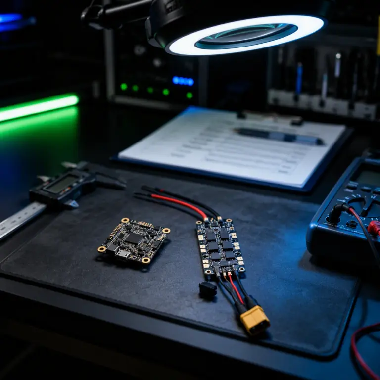
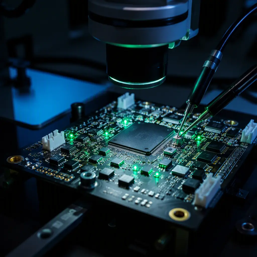
A workable stage architecture for UAV electronics runs in five steps. Automated optical inspection after reflow verifies placement and solder geometry against the reference image, and detects the missing, tombstoned and skewed parts that no electrical test will ever see because they are not in the netlist. In-circuit test on a bed-of-nails fixture verifies that the measured resistance, capacitance and diode drop at each node match the expected value within window, which catches wrong-value parts, reversed polarity, open joints and shorts. Boundary scan or a programming station loads firmware and verifies the digital interconnects the probe card cannot reach on a dense board. Functional test powers the assembly as a working device and exercises its actual interfaces — IMU output over SPI, DShot and CAN output on every motor channel, servo rail under load, telemetry port. Burn-in or thermal soak runs a subset of those functional checks at temperature to expose the marginal units.
The claim each stage is entitled to make is narrow. In-circuit test with 100% coverage — which is rare on a densely populated UAV board, where 70–85% is a realistic figure — proves the network is assembled to the netlist. It does not prove the board boots, does not prove the firmware configures its pins, and says nothing about the sensor noise that decides whether a controller can hold attitude. Functional test is the only stage that makes a claim about the unit as a device, and it is the stage where the specification effort pays back most. If the purchase order demands one test with real value, it should be a specified functional test, not a bare in-circuit report.
 Five test stages, each with a bounded claim
Bed-of-nails or flying probe: choosing the fixture for the board
Both fixtures verify the same class of defect — assembly-level connectivity and component value — but they trade setup cost against throughput and geometry, and the correct choice follows from the production volume and the board's own layout.
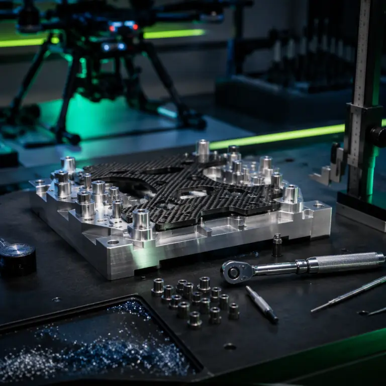
A bed-of-nails fixture probes every node simultaneously through spring-loaded pins, so test time is measured in seconds and the per-unit cost falls to almost nothing at volume. The cost is in the fixture itself: a dedicated probe card with mechanically drilled and precisely located pin positions, which for a complex board runs into thousands of dollars and several weeks of lead time, and which is worthless if the board revision changes. The geometry limit is the real constraint. A probe pin requires a free landing pad of roughly 0.6–1.0 mm diameter with clearance around it, and on a UAV flight controller board — where an IMU footprint may sit within a few millimetres of its decoupling and the whole sensor cluster occupies the centre of the board — those free pads frequently do not exist on the top side. Most bed-of-nails fixtures for drone boards therefore probe from the underside only.
A flying probe moves two or four programmable heads between test points and needs no fixture at all, so it accepts any board revision with no tooling cost and reaches test points that no pin card could access. The cost is throughput: because the heads move sequentially, a board that takes 15 seconds on a bed-of-nails station may take 4–8 minutes on a flying prober. That makes flying probe the natural choice for low-volume and prototype builds, for high-mix programmes where a dedicated fixture would never amortise, and as a first-article verifier that proves the netlist before a bed-of-nails fixture is committed to. It is the wrong choice for a 500-unit monthly build, where the probe time alone will exceed the fixture cost within a month.
The decision rule is a straightforward crossover. Below roughly a few hundred units per year per board revision, flying probe wins on total cost. Above it, bed-of-nails wins on throughput, and the engineering effort shifts to making the probe card's mechanical design survive contact with reality: alignment that does not rely on the operator, probe selection matched to the pad finish, and a fixture that is treated as a calibrated instrument rather than a jig.
The procurement consequence is direct. If a UAV component supplier is running a low-volume line on flying probe and reports in-circuit results, the report is credible but the coverage is likely lower than a bed-of-nails number would suggest, because sequential probing is often limited to a diagnostic subset rather than every node. Ask which fixture produced the data before you compare coverage percentages between two suppliers. The same discipline that applies when evaluating a UAV component supplier applies here in miniature: a number without its method is not evidence.
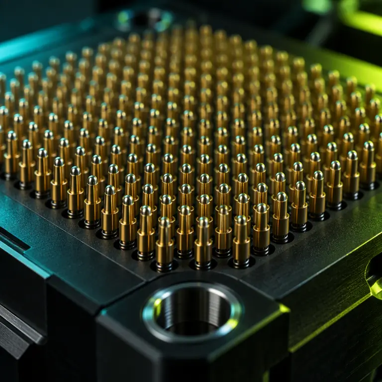 Probe card geometry limits what a pin can reach
The fixture is the most likely source of a false pass
A test station has two independent failure modes and most programmes only manage one of them. A false fail scrapes a good unit and costs money visibly, so it gets attention. A false pass ships a bad unit and costs money invisibly, sometimes years later and often in the field where the diagnosis is expensive. Production test fixtures are far more likely to produce false passes than false fails, because every mechanism of fixture degradation loosens a measurement rather than tightening it.
The mechanisms are concrete and all of them are measurable. Pogo pins carry a rated life, commonly 10 000 to 100 000 mating cycles depending on the series, after which spring force falls and contact resistance rises and becomes variable. Alignment pins wear their bores: a 0.4 mm wear on a locating pin lets the board float enough that a probe designed for a 0.8 mm pad lands on the solder mask instead. Probe tips oxidise and accumulate flux residue, so the resistance at a node climbs gradually and stays inside the pass window while masking a genuinely marginal joint. Board flex under probe force changes contact pressure from the centre of the board to its edges, so the same fixture can measure a node correctly at the corner and poorly in the middle.
Guarding against this is a specification act, not a maintenance habit. Require the fixture to be qualified by measurement rather than by installation: run the same known-good reference board through the station 30 times and record the spread of every measurement, then set the pass windows from that observed spread rather than from the component tolerance. A station whose repeated measurement of a fixed reference varies by more than about 10% of the tolerance window is not measuring to the window it claims to test. Require a scheduled reference-board check with recorded results, probe replacement at a stated cycle count, and a documented correlation between the fixture and a bench instrument so that a change in reading can be attributed to the fixture or to the product. None of this is exotic. It is the difference between a test line and a rubber stamp, and it is the same reasoning that underlies the third-party pre-shipment audit — except that it applies to every unit rather than a sample.
What a functional test station has to simulate
The functional station is where a UAV board is tested as a device, and the specification question is what the station must present to the unit's inputs and what it must measure at its outputs. Get this wrong and the station produces confident passes on units that will fail on the aircraft.
Three requirements dominate. First, the unit must be tested in its correct state. A flight controller or ESC that configures its output pins in firmware will read as faulty if the station probes those pins before the firmware has run. The station must load firmware, wait for a defined ready signal, and only then assess outputs — the sequences that decide the firmware update and configuration workflow in the field apply identically at the test bench, because the failure signature of probing too early is indistinguishable from a real hardware fault.
Second, the load must be realistic. An ESC verified on a station that presents a resistor instead of a motor will not reveal desynchronisation or thermal drift in commutation. A servo-rail measurement taken with no current draw will not reveal the regulator behaviour under the transients a set of digital servos produces. Where a real load is impractical, the station should at minimum present a modelled one and record the assumption explicitly in its protocol, so that the gap between station and aircraft is known rather than assumed away.
Third, the measurement must be a number, not a verdict. A station that reports "pass" is unauditable. A station that records the gyro bias in degrees per second, the current draw at a stated idle condition, the ESC commutation timing at each throttle step, and the receive sensitivity of the radio module in dBm produces data whose drift can be tracked across a production run. That record is what converts a shipment from a claim into a dataset — and it is what lets a programme detect that a supplier silently changed a component or a process between batch 2 and batch 9, because the numbers moved even though the pass verdict did not. For a parameter as consequential as the TVS and grounding network that protects these assemblies, a recorded leakage measurement is the only way to know the protection is still inside specification.
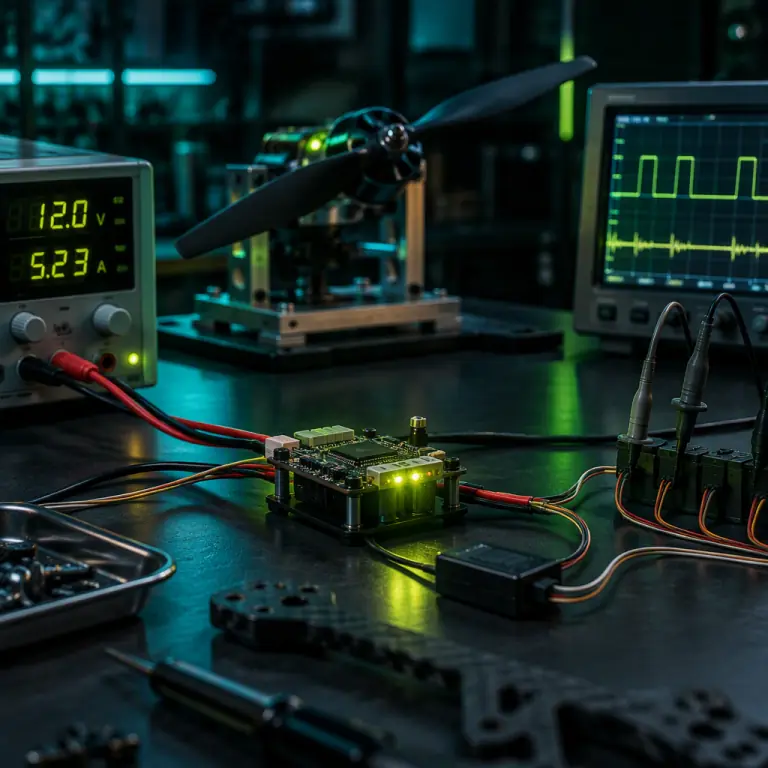 A recorded number is auditable; a verdict is not
The coverage arithmetic matters as much as the capability. A functional station that exercises every interface but tests only at 25 °C is measuring a device that will spend its life at −20 °C through +55 °C and often inside a sealed airframe that runs warmer than ambient. Full thermal qualification is a design-phase activity, correctly placed alongside the MIL-STD-810 and DO-160 environmental qualification work. Production test does not need to repeat that campaign, but it does need a soak stage: a subset of functional checks at the two temperature extremes the product will see in service, applied to every unit rather than to a qualification sample. The distinction is that qualification proves the design once, while the soak stage catches the individual unit that was assembled differently from the one that passed.
Specifying test fixtures and ATE in the RFQ
Production test is a deliverable and belongs in the purchase order in the same way as the component specification. The clauses that carry the most weight are the ones that make test behaviour observable and auditable rather than asserted.
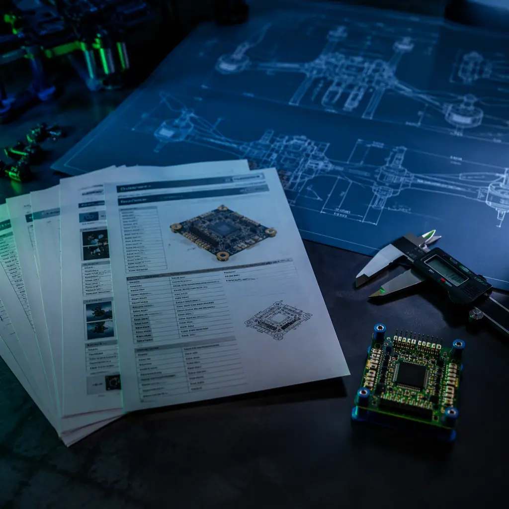
Require the test coverage and the fixture type to be stated per board, not per programme. "In-circuit test" is not a specification; "bed-of-nails in-circuit test with the coverage list and the fixture's calibration interval" is. Require the test protocol to be submitted and reviewed before the first production lot, including what the station measures, the load it presents, the temperature conditions, and the pass window for every measured parameter.
Require the fixture qualification record: the reference-board repeatability study, the probe cycle count at the time of test, the date of the last reference check, and the correlation result against a bench instrument. Require per-serial measurement data rather than a lot-level pass stamp, delivered in a machine-readable file, so that a field failure can be traced back to its production record and to its sibling units. Require the fixture change control commitment — that any revision to a fixture or a station executes after notification and re-qualification, which is where the silent fixture alteration that quietly widens a pass window gets caught.
Finally, require a defined first-article test run: the first units of a new lot or a new revision go through the full station while the customer's representative or an appointed inspection body witnesses it, structurally the same discipline as the first-article inspection covered in the guide to UAV assembly tooling and fixtures — applied to the test line rather than the build line. These go into the same RFQ document whose specification clauses are discussed in writing a UAV component RFP, and they are priced into the unit rather than negotiated afterwards.
What this changes about how you buy UAV electronics
Test evidence is the negotiation point where a UAV component purchase most often goes wrong, because it is the deliverable that looks settled while remaining ambiguous. A supplier reporting 100% pass rate is saying something about a station whose fixture type, coverage, load model, temperature conditions and pass windows are not in the sentence. Those five omissions are where marginal units escape, and marginal units are exactly what a drone programme cannot tolerate.
The practical position is to buy test as a specified deliverable. Ask what the station measures and write it down. Ask for a number rather than a verdict and require the data file with the shipment. Ask how the fixture is qualified and how often, and put the answer in the purchase order. None of these requests is unusual enough to slow a competent supplier down, and the response to them is itself a signal: a supplier with a real test line answers with records, and a supplier without one answers with reassurance. That distinction is more informative than any capability statement, and it costs nothing to establish before the first order rather than after the first field failure.
Send your component list and volume — we will specify the test plan
Tell us the boards in question, the annual and lot volumes, the interfaces each one presents, and the field failure modes you are trying to exclude. We will respond with the recommended test stage architecture, the fixture type and its qualification requirements, the parameter list and pass windows we would propose, the per-serial data format, and the test clauses to carry in the purchase order — reviewed by the engineering team before quotation so the test plan and the component specification are issued as one document.
Explore Testing Capabilities Back to Blog