
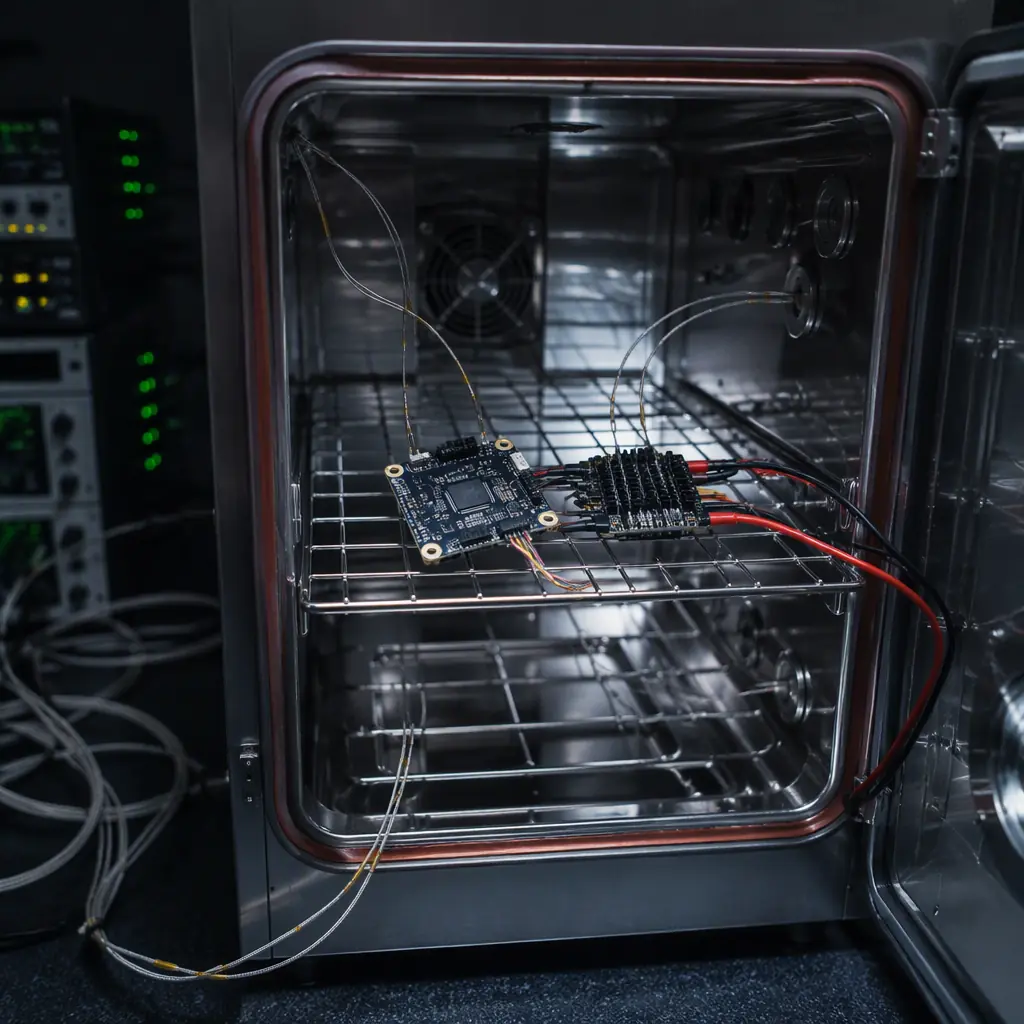
The gap between a component that passes its datasheet checks and a component that survives its mission is environmental exposure. A flight controller can pass every electrical test on the bench and still fail after 200 thermal cycles, when the coefficient-of-expansion mismatch between a BGA package and the PCB finally cracks a ball. An ESC can deliver its rated current at 25 °C and derate itself into a brownout at 55 °C. A telemetry module can pass its range test and then lose the link when vibration loosens the U.FL connector. Environmental qualification testing is the systematic exposure of hardware to the environments it will meet, before the airframe does it for you. The propulsion testing and validation guide covers the thrust-chain tests; this guide covers the environmental test methods from MIL-STD-810 and RTCA DO-160 that every UAV component buyer should understand.
MIL-STD-810 vs DO-160: which standard to specify
Two standards dominate UAV component environmental testing, and they answer different questions. MIL-STD-810 (now 810H) is a U.S. Department of Defense standard describing test methods for military equipment. It is method-oriented, letting the buyer tailor test levels to the platform. RTCA DO-160 (now DO-160G) is the airborne equipment standard used in civil aviation certification (including the EASA/FAA path for UAS). It is category-based, with defined severity levels chosen by the equipment's installation. For UAV components, the practical guidance:
| Aspect | MIL-STD-810H | RTCA DO-160G |
|---|---|---|
| Origin | Military equipment, U.S. DoD | Airborne equipment, civil aviation (RTCA/EUROCAE) |
| Structure | Method per environment (Method 501.7 high temp, 514.8 vibration…) | Sections per environment (Section 4 temperature, 8 vibration…), severity categories |
| Tailoring | Levels tailored by the buyer to the platform | Categories selected by installation class |
| Common UAV use | Defense, public safety, rugged commercial components | Certified aircraft equipment, UAS type certification programs |
| Test report value | Method + tailored levels + measured data | Category + pass/fail per section |
Most rugged commercial UAV components are tested to MIL-STD-810 methods with tailored levels; components intended for certified aircraft are tested to DO-160 categories. Both are only as meaningful as the tailoring. A "MIL-STD-810 tested" claim without the method, level and duration is marketing, not data. The certification and compliance guide explains how these test standards relate to the CE, FCC and export compliance stack.
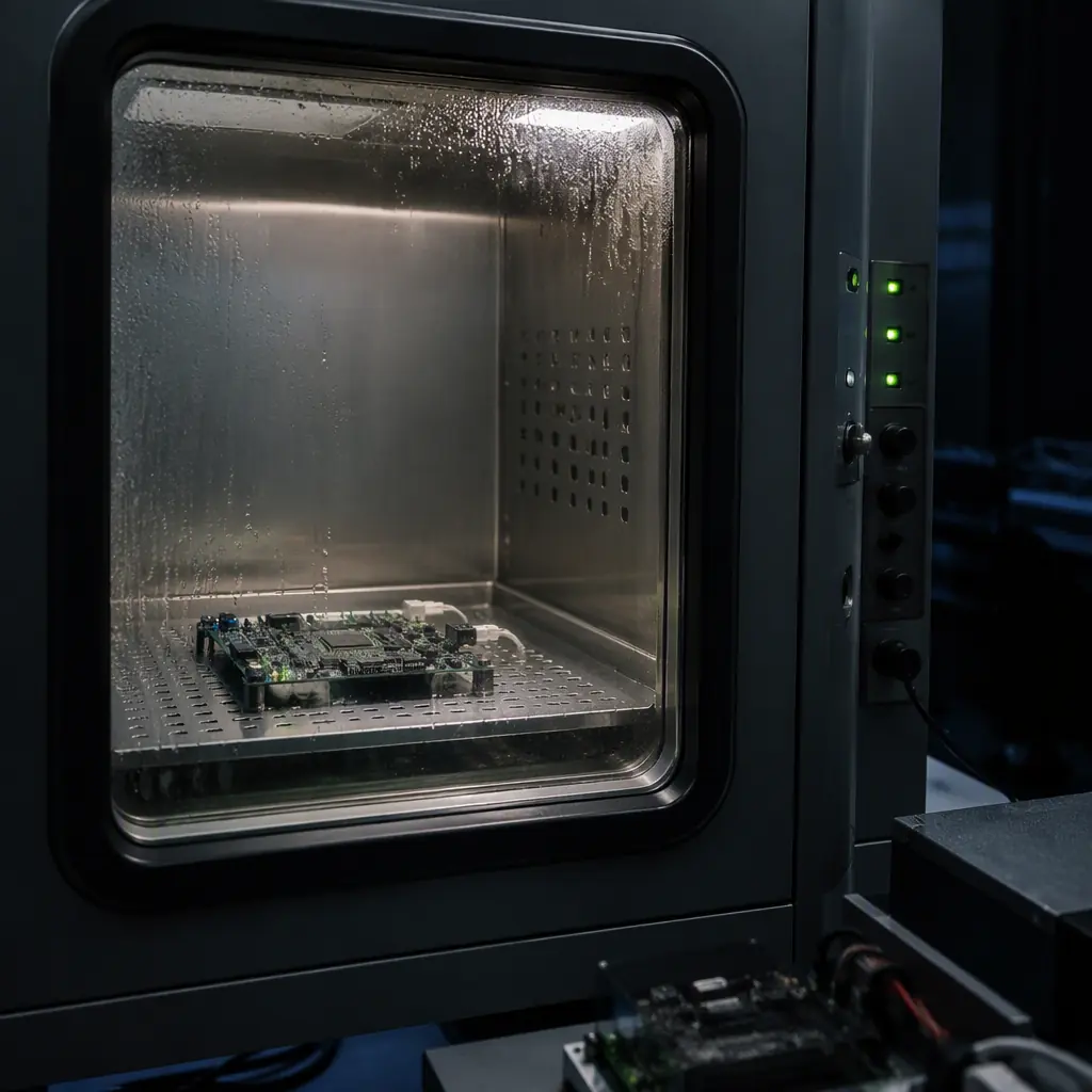 Thermal chamber
Temperature: the test that finds most solder failures
Temperature is the environment that UAV electronics cannot avoid: every flight crosses a thermal gradient, and the daily mission cycle (charge, fly, cool, charge again) is itself a thermal cycle. The two relevant test modes:
- High and low temperature operation and storage (MIL-STD-810 Methods 501.7 and 502.7; DO-160 Sections 4.5.1-4.5.2). The component operates (or survives) at defined temperature extremes for a soak duration. A typical industrial UAV specification is continuous operation -20 °C to +50 °C, with storage -40 °C to +70 °C. And the report must state whether the component was powered during the soak, because powered and unpowered behavior differ.
- Thermal cycling and thermal shock (MIL-STD-810 Method 503.7; DO-160 Section 5). The component is cycled between temperature extremes at a defined ramp rate and dwell time. Thermal cycling is the test that cracks BGA balls, delaminates PCB layers and separates conformal coating, failures that appear only after tens or hundreds of cycles. A credible UAV component qualification runs 50-200 cycles over a range of at least 70 °C.
What to check in the report: the actual temperature at the component (not the chamber set point), the ramp rate, the dwell time, whether the unit was powered, and the pass criteria, including for example, "no intermittent operation, no deviation beyond ±5% on supply current, no data errors on the serial bus." The thermal management guide covers the design side that keeps components inside these limits in flight.
Vibration and shock: what 500 flight hours does to a connector
Propeller-driven vibration is the defining mechanical environment of a UAV. A multirotor at hover excites its airframe at the rotor blade-pass frequency: typically 50-150 Hz for a 15-30 cm propeller at 5,000-12,000 RPM, plus broadband turbulence and motor harmonics. The test methods:
- Random vibration (MIL-STD-810 Method 514.8; DO-160 Section 8). The component is driven with a random vibration spectrum (PSD, power spectral density, in g²/Hz) across typically 10-2,000 Hz, for a defined duration per axis. UAV components are commonly qualified at 2-6 g RMS over 1-2 hours per axis, on all three axes. The failures this finds: connector fretting, solder fatigue, component lead cracking, fastener loosening.
- Resonance search and sine sweep. A low-level sine sweep identifies the component's resonant frequencies; the design goal is to keep the primary resonances away from the rotor excitation band, or to damp them. A component whose resonance sits at 60 Hz on a 6,000 RPM multirotor will vibrate itself apart.
- Shock (MIL-STD-810 Method 516.8; DO-160 Section 7). Half-sine or sawtooth pulses: typically 20-40 g, 11 ms for operational shock on a rugged UAV component, with 6 orientations. Shock finds brittle failures: ceramic capacitor cracking, crystal oscillator damage, solder joint fracture at the board edge.
The report must include the PSD profile (not just the g RMS), the duration per axis, the mounting method (because mounting changes the response), and functional checks during and after the test. A component that passes vibration with a foam mount and fails hard-mounted is a component that will fail in service, the report's mounting photos matter. The propeller balancing and vibration guide covers the airframe-side reduction of the same excitation.
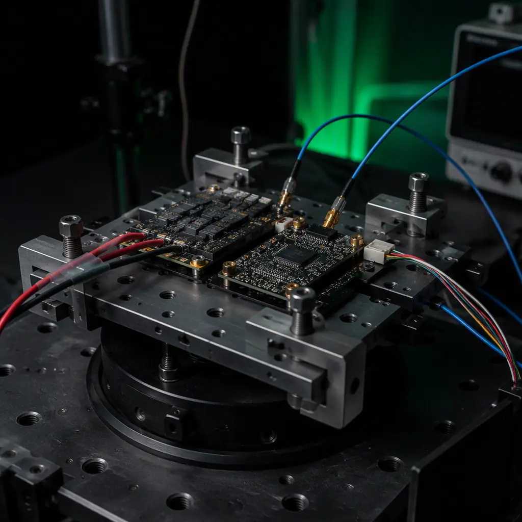 Vibration test rig
Humidity, salt fog, sand and dust: the corrosion and abrasion trio
Environmental qualification is not only about physics, it is about chemistry. Three test families cover the corrosive and abrasive world a UAV flies through:
- Humidity (MIL-STD-810 Method 507.6; DO-160 Section 6). The component is exposed to high relative humidity (typically 95% at 30-60 °C) in cycles that cause condensation. The failure mode is electrochemical: moisture + bias voltage + ionic contamination = dendritic growth and leakage currents. Condensation on powered electronics is the reason UAV avionics need conformal coating, the electronics manufacturing quality guide covers the IPC-A-610 and coating standards that make humidity test pass rates respectable.
- Salt fog (MIL-STD-810 Method 509.7). A 5% NaCl fog at 35 °C, typically 24-48 hours, accelerates corrosion of unprotected metals. It is the test for coastal operations, offshore inspection and maritime logistics UAVs. Bare aluminum, non-stainless fasteners and uncoated connectors fail fast; the report should state the exposure duration and the acceptance (no functional degradation, no red rust on critical surfaces).
- Sand and dust (MIL-STD-810 Method 510.7). Airborne dust (blowing dust, typically 10-150 µm particles) and blowing sand (150-850 µm) test seal integrity and abrasion resistance. For UAVs this is the desert and agricultural environment test, the same environment covered on the mission side by the agriculture components guide. Dust ingress into gimbal bearings, connectors and cooling intakes is a leading cause of field failure in arid regions.
The waterproofing and IP ratings guide connects these tests to the IP code. An IP67 rating is a separate verification (dust-tight + immersion) that complements, but does not replace, MIL-STD-810 corrosion testing.
Altitude and pressure: the derating nobody budgets for
Altitude testing (MIL-STD-810 Method 500.6; DO-160 Section 4.6) covers two distinct effects that UAV operations at 1,000-5,000 m altitude trigger:
- Reduced cooling. Air density at 3,000 m is about 70% of sea level, so convective cooling of ESCs, motors and batteries drops by roughly the same fraction. A propulsion system thermally validated at sea level can overheat at altitude under the same load, the reason the heavy-lift propulsion design guide insists on altitude-aware thermal margins.
- Reduced dielectric strength and pressure differentials. Lower pressure reduces the breakdown voltage of air (relevant for high-voltage power electronics) and creates pressure differentials across sealed enclosures, the venting problem covered in the waterproofing guide's pressure-equalizing vent section. A sealed payload at 4,000 m with no vent sees internal overpressure that can push moisture past gaskets on descent.
The report should state the tested altitude (or the chamber pressure in kPa), the powered or unpowered state, and the functional criteria: for example, "full throttle endurance at 3,000 m simulated altitude with no thermal derating beyond the specified curve."
How to read an environmental test report
An environmental test report is only as useful as its completeness, and UAV component reports vary from a single sentence ("temperature tested OK") to full data packages. The five checks that separate a real qualification from a checkbox:
- 1. Method and standard stated. "MIL-STD-810H Method 501.7, Procedure I (storage)" with the standard revision, not "tested to MIL-STD-810".
- 2. Tailored levels and durations. Temperature range, soak hours, cycle count, PSD profile, g RMS, duration per axis. A report without levels is a brochure.
- 3. Powered or unpowered. Whether the unit was operating during each phase. Powered testing is harder and more meaningful for electronics.
- 4. Functional pass criteria. What "pass" meant: measured current draw, data integrity, timing, output accuracy, not "no visible damage".
- 5. Sample count and serialization. How many units, from which batch, with serial numbers. One hand-picked unit is not a qualification.
For procurement, these checks belong in the RFP, the UAV component RFP guide shows how to write test clauses with defined verification, and the supplier evaluation checklist shows how to score the responses. Environmental test data is one of the clearest signals of a manufacturer that tests what it ships: a supplier that publishes full reports with serial numbers is a supplier that runs the tests.
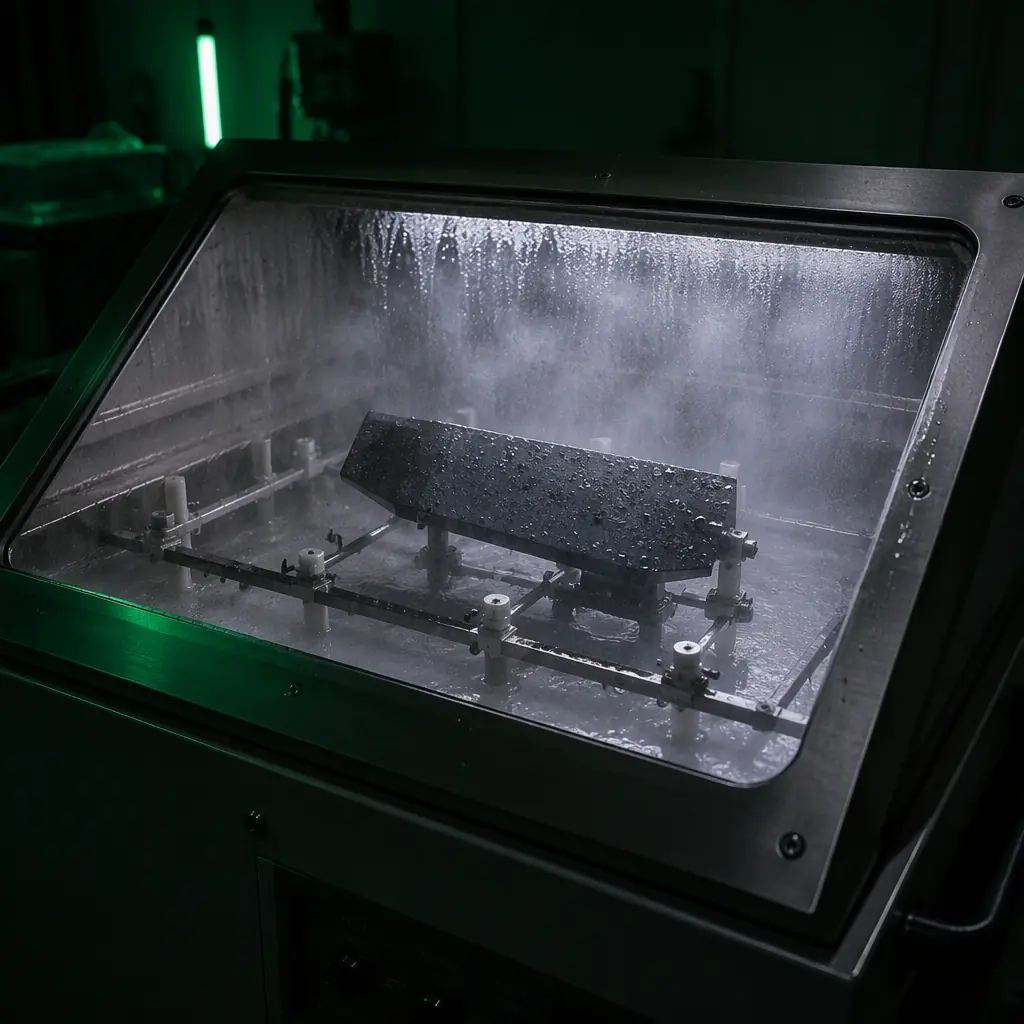 Salt fog chamber
Specifying environmental testing in procurement: the minimum clause
A workable environmental qualification clause for a UAV component purchase, covering the mission profile the buyer knows (operating region, flight altitude, coastal or desert exposure, flight hours per year):
- Temperature: continuous operation -20 °C to +50 °C, storage -40 °C to +70 °C, 100 thermal cycles over the operating range, powered during cycling, with measured supply current and no data errors.
- Vibration: random vibration 10-2,000 Hz, 4 g RMS, 1 hour per axis, three axes, hard-mounted, functional check at 0 dBm RF output stability and no connector discontinuities.
- Humidity: 95% RH at 40 °C, 10 cycles with condensation, powered, leakage current below the datasheet limit.
- Salt fog and dust: only if the operating environment requires them, coastal and desert missions respectively, 24-48 h salt fog, blowing dust per Method 510.7, acceptance = no functional degradation.
- Reporting: serial-numbered per-unit test reports with the standard, method, levels, durations, mounting photos, and functional data, delivered with the hardware.
The bottom line: environmental qualification is how a component buyer converts "it works on the bench" into "it works on the airframe, in the region, for the mission." The standards exist, the methods are documented, and the difference between suppliers is whether the test data exists and whether it is real. EMS Drone tests every critical component, flight controllers, ESCs, RF modules, with powered functional checks and thermal cycling as standard, and can supply MIL-STD-810-style environmental test data, vibration profiling and altitude testing for custom stacks. Send the operating environment and the mission profile, and we will return the test plan that matches it.
Explore testing & validation Back to Blog
EMS Drone manufactures qualification-tested avionics under one roof, from component sourcing through production test. If you are specifying for a build, see the full capability set and the tolerances we hold.
Continue Reading
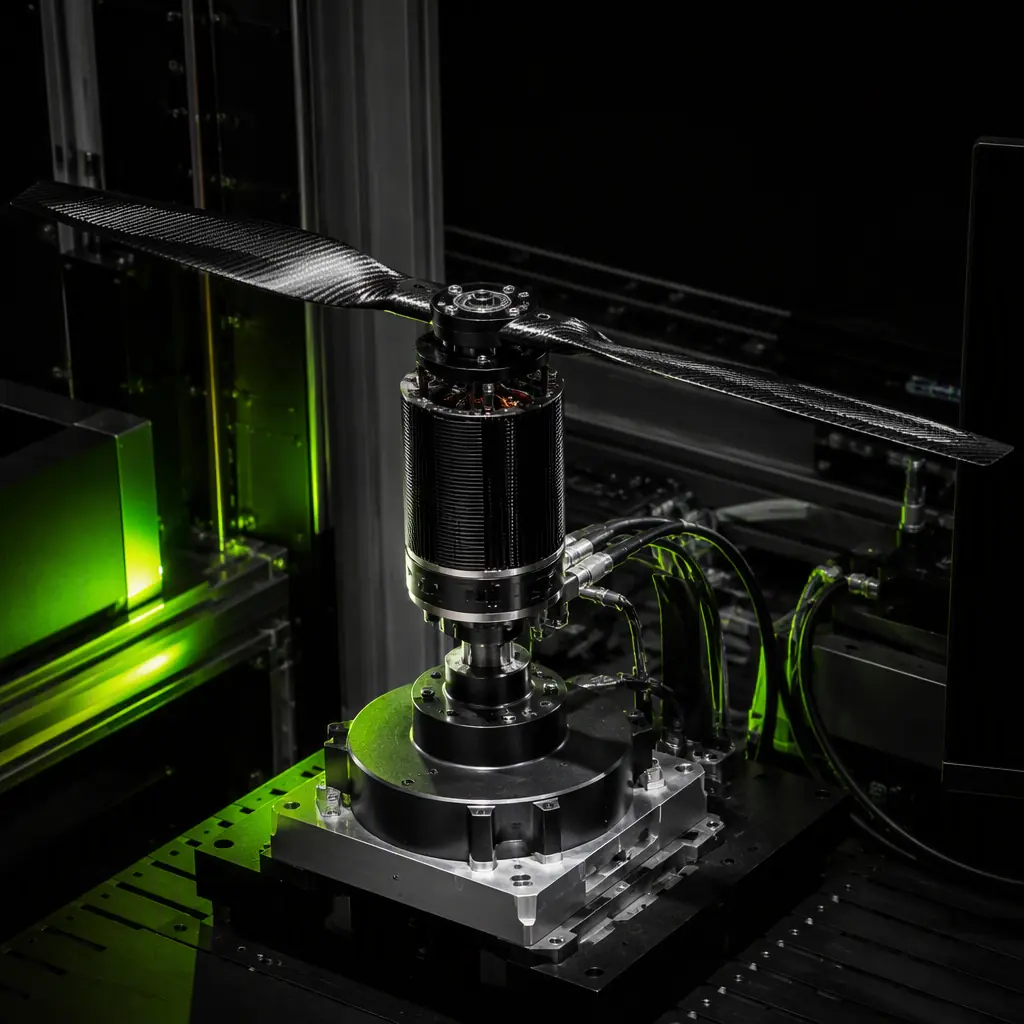
UAV Propulsion Testing and Validation
The thrust-chain test philosophy that pairs with environmental qualification.
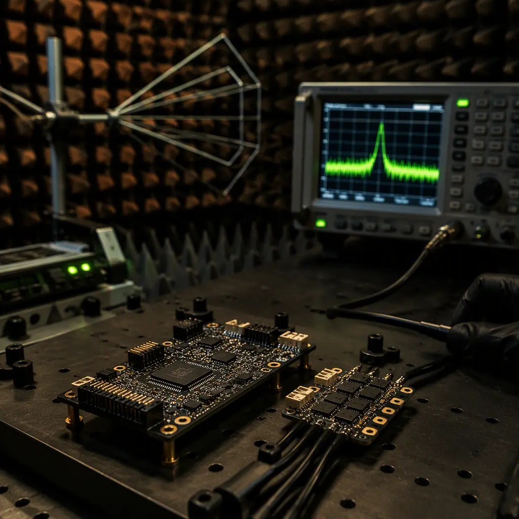
UAV Avionics EMC and EMI
The electromagnetic test methods that run alongside environmental qualification.
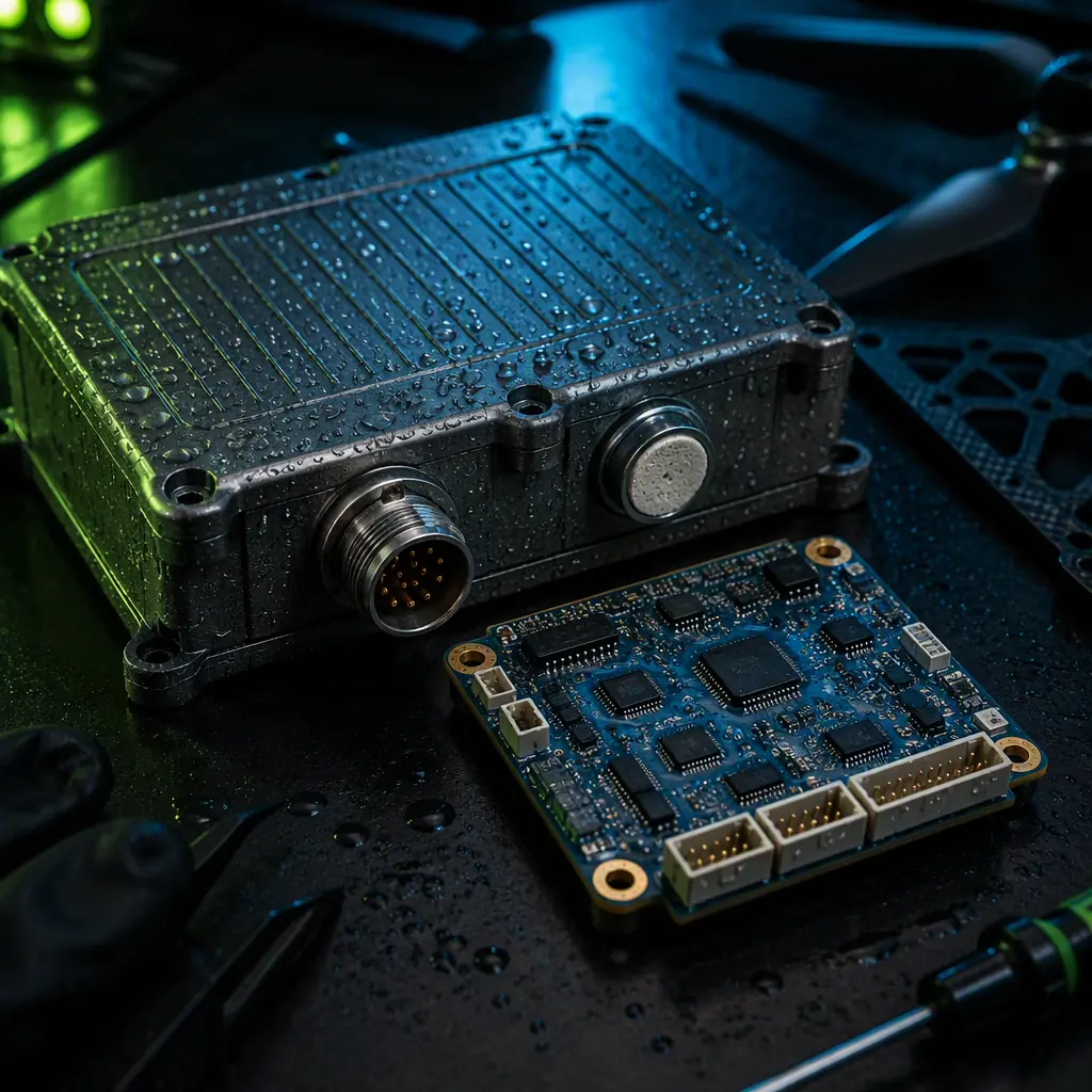
UAV Waterproofing and IP Ratings
How IP ingress verification complements MIL-STD-810 corrosion testing.
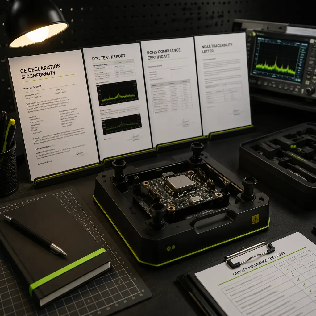
UAV Certification and Compliance
Where test standards fit in the CE, FCC and export compliance stack.
Writing a UAV Component RFP
How to write the environmental test clause into the specification and acceptance criteria.