
Every UAV program reaches the same milestone: the day the aircraft stops being a prototype and becomes a fleet. At that point the firmware question changes character. A single aircraft can be reflashed at the bench by an engineer; twenty aircraft spread across three operating sites cannot. The update pipeline becomes infrastructure — and like all infrastructure, it is either designed deliberately or improvised badly. The engineering reality is that an OTA update for a UAV is not a file transfer; it is a state transition of a safety-critical system performed over an unreliable radio link, with the possibility of power loss, link loss or a corrupted image at every step. This guide breaks the problem into the five layers a procurement specification must address: the update channel, the boot-chain security, the atomic mechanism, the fleet version control, and the in-flight behavior rules.
Why OTA is now a procurement requirement, not a convenience
The shift from bench reflashing to over-the-air updates is driven by three concrete pressures, each of which shows up in a written requirement rather than a wish list:
Security patches. UAV flight controllers and companion computers run real operating systems and real network stacks, and the vulnerability disclosures now arrive on the same cadence as the drone industry. When a vulnerability is disclosed in an autopilot stack or a radio protocol, the exposure window is measured in days, not weeks — a fleet that must be physically recalled to be updated is a fleet that flies with the vulnerability for that entire window. The UAV defense and security components guide treats the patching path as part of the security architecture for exactly this reason.
Regulatory linkage. Remote ID firmware versions are tied to the declaration of compliance: an aircraft whose Remote ID broadcast format changes in firmware must match the version recorded in the operator's documentation. The Remote ID and BVLOS components guide covers the compliance side, and the practical consequence is that the operator needs a controlled, traceable way to move the fleet to the new version — not a box of micro SD cards.
Fleet economics. The UAV fleet management components guide documents the maintenance loop that scales with fleet size: an update path that requires physical access costs a technician day per aircraft per update. At twenty aircraft and four updates a year, that is eighty technician days — the entire business case for OTA is recoverable from that line item alone.
The update channel: what "over-the-air" actually means for a UAV
The channel is the first decision, and it is a bandwidth and reliability budget, not a marketing label. The realistic options for a UAV, in order of increasing payload size:
- Radio telemetry link (868/915 MHz, 2.4 GHz). Typical effective throughput after protocol overhead is 10–100 kbps. A 4 MB flight controller firmware image takes 5–50 minutes at these rates — feasible for a single aircraft on the bench, marginal for a fleet, and exposed to link loss for the entire window. This is the channel for small, infrequent updates.
- Cellular (4G/LTE, 5G). Throughput in the hundreds of kbps to several Mbps, available whenever the aircraft is within coverage — which for logistics and inspection operations is most of the time. This is the practical fleet update channel, and it is the reason the UAV RF communication systems guide treats the data link as a bidirectional resource rather than a telemetry-only pipe.
- Local Wi-Fi or Ethernet during servicing. Tens of Mbps, used for initial provisioning, large payload firmware (companion computer images in the hundreds of MB) and recovery from a failed update. Not OTA in the strict sense, but the mandatory fallback path in the update architecture.
The specification number that matters is not the peak throughput but the update time and the link-loss behavior: "a 4 MB flight controller image shall transfer and verify in under 10 minutes over the cellular link, and the process shall be resumable from the last complete block after link loss." That sentence forces the supplier to think about chunking, checksums and resumption — the properties that make a radio-link update survivable.
 Concept illustration
Signed firmware and the boot chain: verifying what actually runs
The most common OTA failure is not a dropped packet — it is a malicious or corrupt image that the aircraft accepts and boots. The defense is the signed boot chain, and it has three links that must all be specified:
Image signing at build time. Every firmware image is signed with the manufacturer's private key; the signature covers the image hash, so any modification invalidates it. The signature algorithm and key length are the procurement-relevant details — a minimum of Ed25519 or ECDSA P-256 is the current benchmark; SHA-1-signed images should be rejected on sight.
Signature verification at boot. The bootloader verifies the signature of the application image before executing it, using a public key stored in a write-protected region — ideally a secure element or a one-time-programmable memory. If verification fails, the bootloader refuses to boot the image and falls back to the last known-good version. This is the property that turns "the aircraft will not run unverified code" from a slogan into a testable requirement.
Key management and rotation. The private key must never be on the aircraft, the update server must be able to sign images offline, and the aircraft must support key rotation so a compromised key can be revoked. The UAV electronics manufacturing quality guide covers the factory side — the programming, the write-protection and the serialized key provisioning that happen before the aircraft ships.
The test that belongs in the acceptance criteria: "the aircraft shall refuse to boot an unsigned or incorrectly signed image, and shall report the verification failure to the ground station." A supplier that cannot demonstrate this on a bench test does not have a secure update path — it has a file transfer.
A/B partition and atomic update: protecting the aircraft from a failed flash
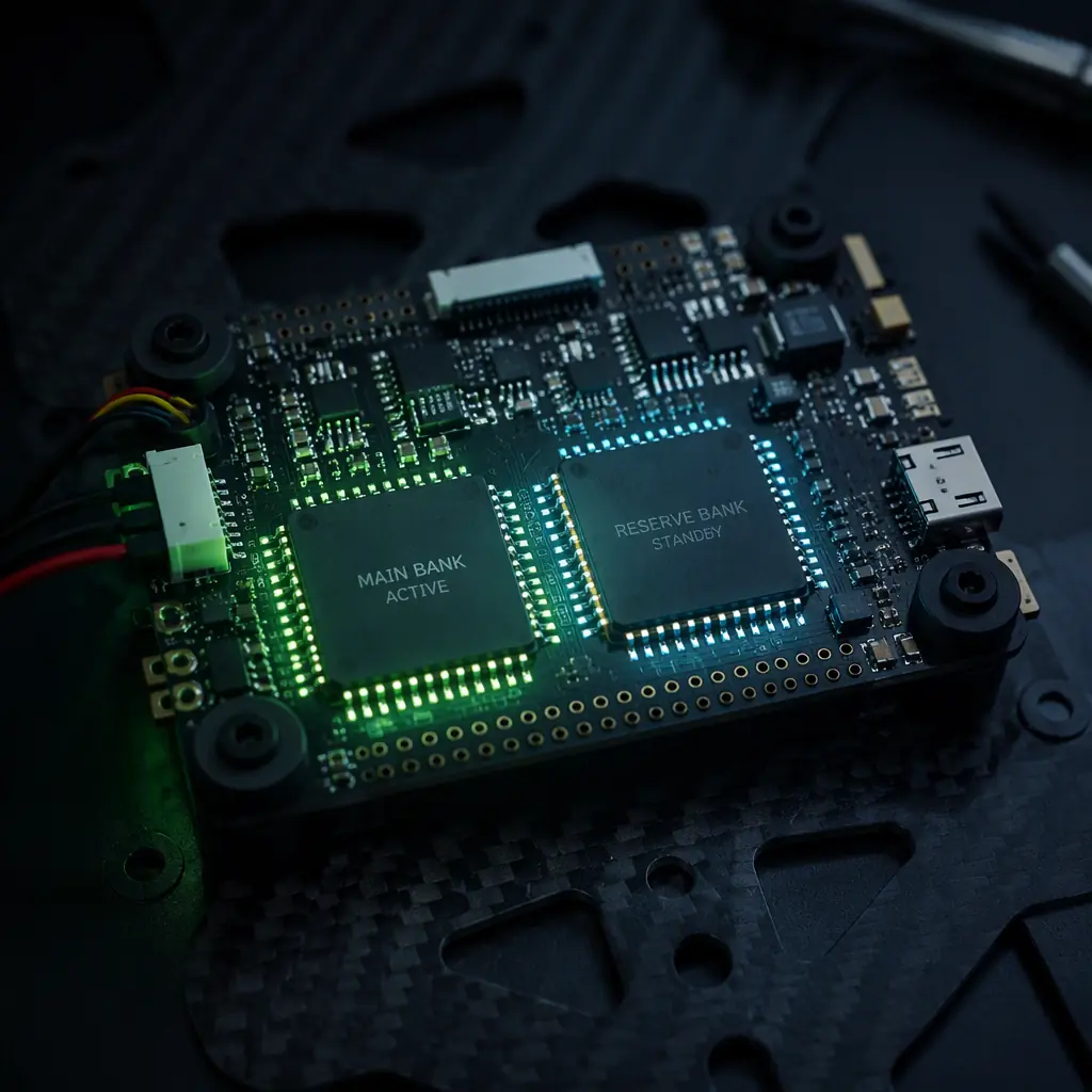
The second structural defense is the atomic update mechanism — the reason a failed flash cannot leave the aircraft un-bootable. The industry-standard architecture is A/B partitioning: the firmware storage is divided into two banks, the active bank (A) and the standby bank (B). The update writes the new image to the standby bank, verifies it completely, and only then flips the active flag. If the new image fails verification, the flag never flips and the aircraft keeps running the old, known-good image. The update becomes a two-phase commit:
- Download phase. The image transfers to the standby bank, chunk by chunk, with checksums. A link loss here is harmless — the transfer resumes or restarts, and the active bank is untouched.
- Commit phase. The image is verified (hash and signature), the boot flag is updated, and the aircraft reboots into the new version. The commit is a single atomic step — power loss exactly at this moment leaves the aircraft able to boot the previous version on the next power-up, because the flag write is itself protected.
- Post-boot confirmation. The new image runs a self-check and reports success to the ground station; only then does the system consider the update complete. If the new image fails its self-check, the bootloader rolls back automatically to the previous bank.
The cost of A/B partitioning is flash capacity — the storage requirement doubles, and the flight controller needs enough non-volatile memory for two full images. For a flight controller with a 4–8 MB image, that means a 16–32 MB flash part, which is a routine component today. The ESC firmware selection guide shows the same pattern on the ESC side — the modern ESC protocols support firmware updates over the CAN bus, and the same dual-bank logic applies to the ESC's own flash, where a bricked ESC is a much harder field repair than a bricked flight controller.
 Concept illustration
Rollback and fleet version control: the operational discipline
The technical mechanism is only half of the system; the operational half is fleet version control — knowing what version is on every aircraft, and being able to move the fleet forward or backward deliberately. The three artifacts a fleet operator needs:
A fleet version matrix. A record of aircraft serial number, current firmware version per component (flight controller, ESC, radio, companion computer, payload), and update history. This is the input to every update decision and the evidence for any compliance audit. The UAV component obsolescence management guide covers why the version matrix is also the obsolescence record — a component whose firmware can no longer be updated is a component approaching end-of-life.
A staged rollout policy. The fleet is never updated all at once. The standard pattern is canary → pilot group → full fleet: one aircraft first, then a small operational group, then the rest after a defined observation period (typically 24–72 hours per stage). This turns a bad release from a fleet-wide grounding into a one-aircraft incident. The rollout stages should be written into the update policy, not improvised at release time.
A rollback trigger. The policy must name the conditions that trigger a rollback — a defined set of failure symptoms (altitude hold error, ESC desync, telemetry dropout rate above threshold) observed within a defined window (usually the first operational flights after update). Because the A/B mechanism keeps the previous image available, a rollback is a config change, not a reflash.
The version control question is also an autopilot question: the ArduPilot vs PX4 guide compares how each open-source stack handles release channels, parameter compatibility and version migration — differences that matter when the fleet operator must decide whether a minor autopilot release is safe to push OTA or must wait for a bench cycle.
 Concept illustration
Update behavior during flight: when the aircraft may and may not update
An OTA update on a flying aircraft is a different problem from an update on the ground, and the specification must say explicitly which is allowed. The safe architecture is simple: ground-only update, with a defined state gate. The aircraft shall accept an update only when it is on the ground, the motors are disarmed, and the battery state of charge is above a threshold (typically 30–50%, depending on the flash duration and the risk of a power-loss mid-commit).
The reason is power, not bandwidth: a flash write is atomic only if power is held through the commit. A LiPo at low state of charge under load can sag below the flight controller's minimum input voltage exactly when the commit writes the boot flag. The UAV battery and power management guide covers the power-budget side — the same voltage sag analysis that sizes the power system for flight applies to the flash path.
Two additional in-flight rules belong in the spec. First, no update over a link that is in use for control: if the telemetry link is also the update channel, the update traffic must be throttled so that control and telemetry frames have priority — a firmware download must never crowd out the control link. Second, no auto-update: the aircraft shall never initiate an update without an explicit operator command, and the update command shall require a confirmation step. A UAV that "auto-updates" on the ground station's schedule is a UAV whose operator has surrendered the decision.
 Concept illustration
Remote ID, compliance and the update audit trail
The regulatory layer ties the technical update path to the compliance record. The pattern that matters: a Remote ID firmware change alters the broadcast message format, and the operator's declaration of compliance references a specific firmware version. An aircraft updated in the field without a record creates a compliance gap — the aircraft broadcasts a format that the operator's documentation does not cover. The UAV certification and compliance guide covers the CE/FCC/RoHS side, and the Remote ID and BVLOS guide covers the broadcast-format details; the OTA system's contribution is the audit trail:
- Update log per aircraft. Serial number, previous and new firmware versions, image hash, timestamp, initiating operator, and the verification result. The log is append-only and stored both on the aircraft and on the ground station.
- Compliance mapping. The update system records which regulation-relevant components (Remote ID transmitter, navigation, radio) changed in each update, so the operator can regenerate the declaration-of-compliance evidence after any fleet movement.
- Signed update records. The same signing infrastructure that protects the firmware protects the log — a tampered log is detectable, which is the property a regulator's audit actually checks.
For defense and dual-use programs, the audit trail crosses into the export-control conversation: the UAV export logistics and ITAR/EAR shipping guide notes that the firmware configuration shipped with an aircraft is part of the export documentation, and an OTA update that changes the configuration after export should be traceable for the same reason.
The RFQ checklist: 10 line items for specifying OTA capability
The following line items translate the OTA architecture into an RFQ-ready specification. Each item names the evidence the supplier should provide, and the checklist works for a flight controller, an ESC with bus-update capability, or a complete aircraft program.
1. Update channel. The update path (cellular, radio telemetry, local) and the minimum sustained throughput per channel. Verification: the interface document and a measured transfer test.
2. Image signing. Signature algorithm (minimum Ed25519 or ECDSA P-256) and the signing/key-management process. Verification: a sample signed image and the verification toolchain.
3. Secure boot. The bootloader shall verify the signature before executing any image, using a write-protected key store. Verification: a bench demonstration of refused unsigned image.
4. A/B partition. The update shall write to a standby bank and commit atomically. Verification: the memory map documentation and a forced-power-loss test showing the aircraft boots the previous version.
5. Resumable transfer. A link loss during download shall not corrupt the update; the transfer resumes from the last complete block. Verification: a link-drop test at a defined point in the transfer.
6. State gate. The aircraft shall accept updates only on the ground with motors disarmed and battery above the stated threshold. Verification: the state-machine documentation and a test attempting update in flight (must be refused).
7. Rollback. The previous image shall remain bootable and the rollback shall be a configuration action, not a reflash. Verification: the rollback procedure and a triggered-rollback test.
8. Version reporting. The aircraft shall report the current version of every updateable component to the ground station. Verification: the version-report message and a capture.
9. Update audit log. Append-only per-aircraft update records with hashes and operator attribution. Verification: the log format and a sample log.
10. Key rotation. The system shall support rotating the signing keys and revoking a compromised key. Verification: the rotation procedure and a revocation test.
The component context for the rest of the update chain is covered in the UAV communication protocols guide — the CAN, DShot and bus-level update mechanisms that move firmware between boards — and the UAV safety and redundancy systems guide, which covers how the update state machine interacts with the fail-safe architecture.
Explore custom engineering Back to Blog
Continue Reading

ESC Firmware: BLHeli_32 vs AM32 vs FOC
The ESC-side update mechanisms — CAN-bus firmware updates, dual-bank flash and the firmware support-lifetime question.
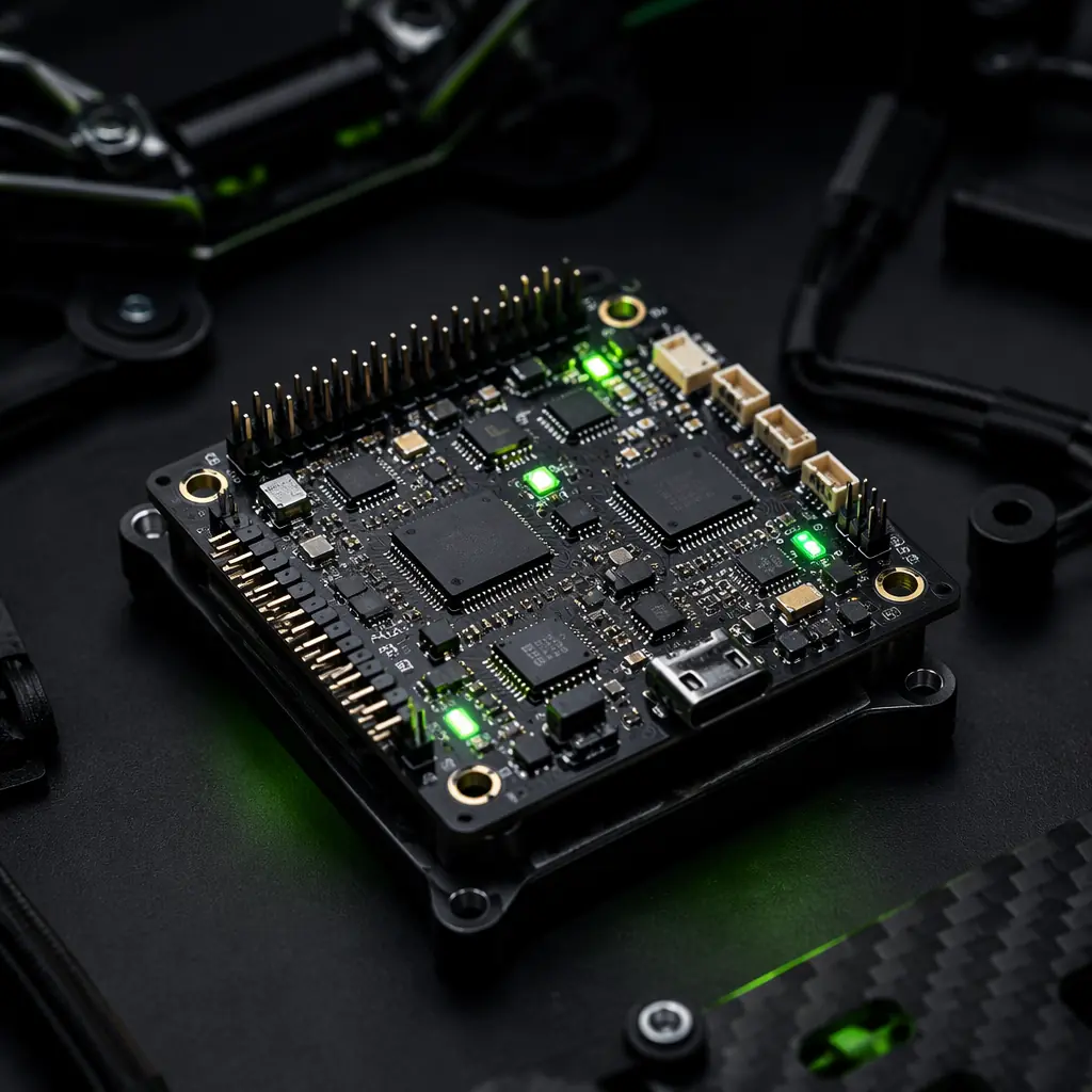
ArduPilot vs PX4: Open-Source Autopilot Comparison
How the two autopilot stacks handle release channels, version migration and parameter compatibility across updates.
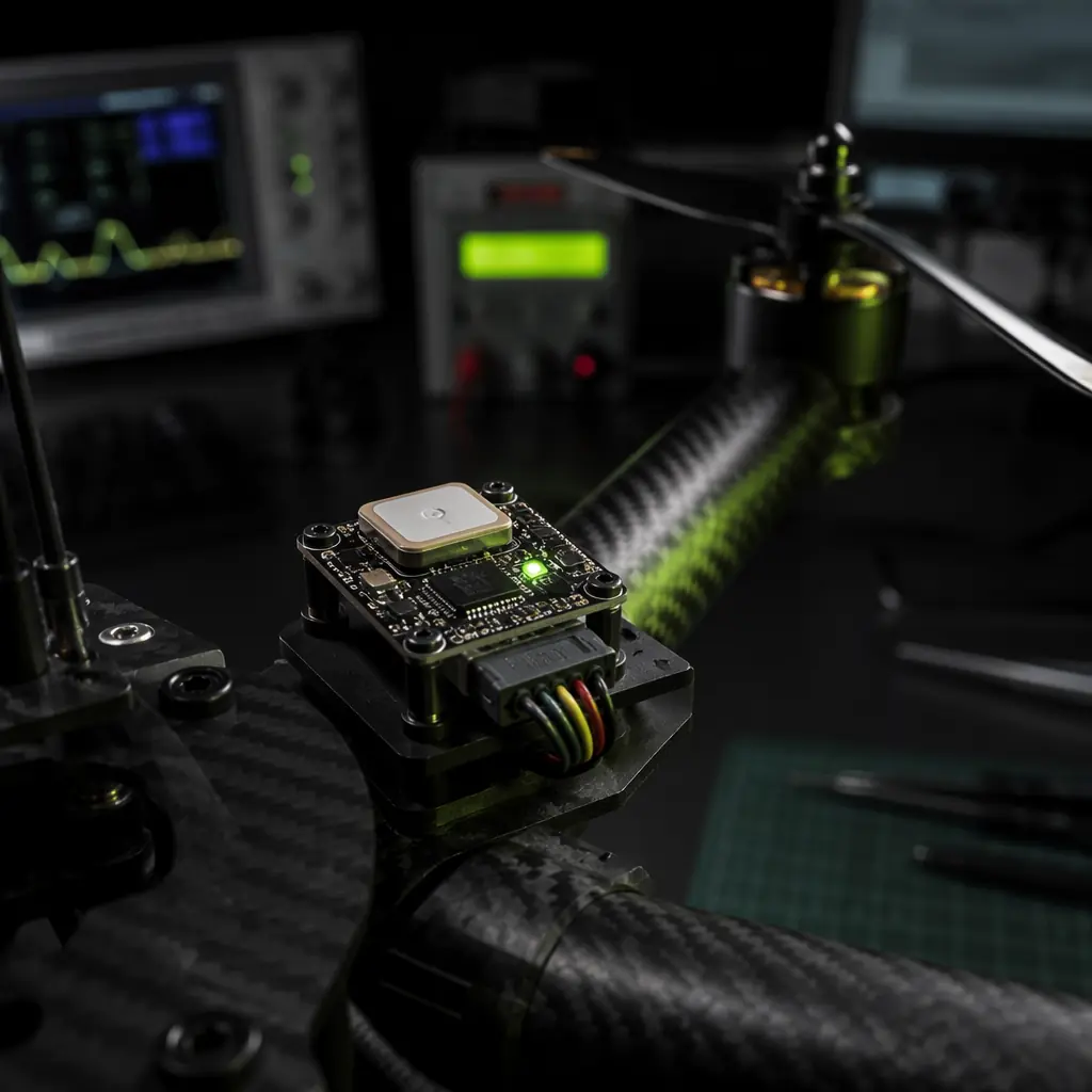
UAV Remote ID and BVLOS Compliance Components
Why the Remote ID firmware version must match the declaration of compliance — and how OTA updates affect it.

UAV Fleet Management Components
The maintenance loop that scales with fleet size — and why the update path is a fleet-management decision.
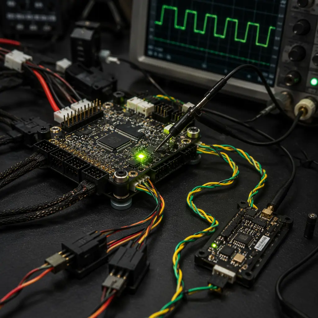
UAV Communication Protocols: CAN, DShot, PWM, SBUS, CRSF
The bus-level update mechanisms that move firmware between flight controller, ESCs and peripherals.