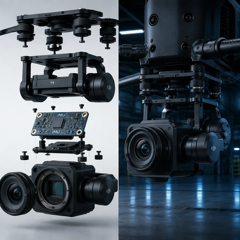
Conceptual UAV payload system with camera, gimbal and sensor integration visualization Concept illustration
Capabilities / Payload

Payloads & Sensors

The mission layer: cameras, thermal imagers, LiDAR, spray systems, drop mechanisms and specialist sensors — everything the aircraft carries to do its job.

RoleMission Equipment
TypesCamera / Sensor / Gimbal / Spray / Drop
Key InterfacesMechanical / Power / Data / Control
ScopeSingle Device → Integrated System
Overview

The payload defines why the aircraft flies.

Without a payload, a UAV is just a propulsion system with a flight controller. The payload — camera, sensor, sprayer, gripper or release mechanism — is the reason the aircraft exists. Payload selection influences weight distribution, power budget, vibration isolation, communication architecture and flight endurance. Integrating a payload means solving four interconnected domains: mechanical mounting, electrical power, data transmission and control interface. Each domain must be addressed for mission success; a payload attached but not powered, or powered but not commanded, is dead weight.

Camera gimbal assembly with thermal imaging sensor, RGB camera, and quick-release mounting plate Concept illustration
Payload Types

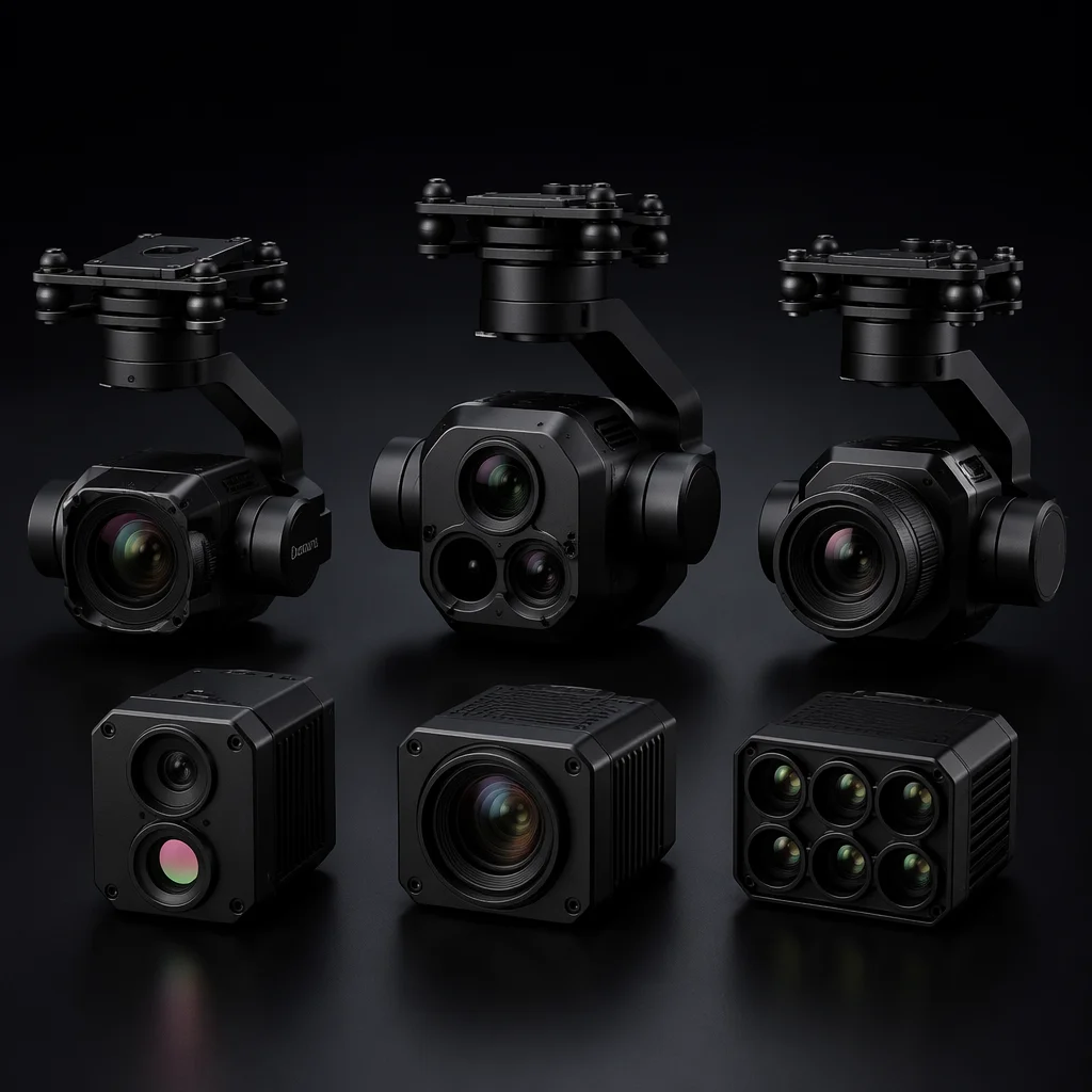
Six payload categories spanning the industrial UAV mission spectrum.

From passive imaging to active delivery, each payload type has distinct integration requirements for mounting, power, data and control.

RGB Cameras

High-resolution visible-light imaging

20–61 MP sensors with mechanical or electronic shutter for photogrammetry, inspection and cinematography. Sony A7R series and Phase One industrial cameras for mapping; Sony UMC-R10C and similar purpose-built survey cameras with intervalometer trigger inputs. The camera must support shutter synchronization with the flight controller for geotagging accuracy — either via hot-shoe trigger adapter, PWM cable or MAVLink camera command. Lens selection (24 mm, 35 mm, 50 mm equivalent) trades ground sample distance against coverage swath width. Onboard recording to SD/SSD with simultaneous HDMI output for a live preview downlink is the standard configuration for professional mapping workflows.

  • 20–61 MP
  • Mechanical shutter
  • Geotag sync
  • HDMI preview
  • Photogrammetry
Thermal Cameras

Radiometric long-wave infrared

Uncooled microbolometer sensors (FLIR Boson, DJI H20T thermal module) at 320x256 to 640x512 resolution, 7.5–13.5 um waveband. Radiometric models record per-pixel temperature data with accuracy typically within +/-5 degrees C or 5% of reading — essential for solar panel inspection, building thermal audit, electrical substation survey and search-and-rescue. Non-radiometric thermal cameras provide visual heat contrast only, not calibrated temperature measurement. Lens options (wide FOV for area survey, telephoto for standoff inspection) determine the working distance for a given target size. Dual-sensor payloads combine a thermal core with a visible-light camera for overlay and picture-in-picture presentation at the ground station.

  • 640x512 LWIR
  • Radiometric
  • Solar inspection
  • Search & rescue
  • Dual-sensor
Multispectral

Vegetation index and crop analysis

Multiple narrow-band sensors — typically Red, Green, Blue, Red Edge (717 nm) and Near-Infrared (840 nm) — with a calibrated reflectance panel and downwelling light sensor (DLS) for ambient light correction. MicaSense RedEdge-MX and Altum-PT are the common platforms, with the Altum adding a thermal band for combined vegetation stress and water status analysis. Used for precision agriculture: NDVI, NDRE, NDWI and chlorophyll index mapping. Multispectral data requires post-processing in specialized photogrammetry software (Pix4Dfields, Agisoft Metashape) to generate orthomosaic reflectance maps and vegetation index layers. Flight planning must account for solar angle consistency across the survey area.

  • 5–6 band
  • NDVI / NDRE
  • DLS correction
  • Precision ag
  • Calibrated panel
LiDAR

3D point cloud generation

Airborne laser scanning payloads (YellowScan, Rock R3 Pro, DJI Zenmuse L2) combining a laser scanner, survey-grade IMU and dual-frequency GNSS into a single integrated unit. Scan rates from 100 kHz to 1.2 MHz with ranging accuracy of 1–3 cm. Multiple returns per pulse enable ground detection under vegetation canopy — a capability that photogrammetry alone cannot provide. Applications: terrain modeling under tree cover, corridor mapping (power lines, pipelines), volumetric stockpile measurement and digital twin creation. LiDAR requires a rigid mechanical mount (any flex between the sensor and IMU introduces point-cloud error), post-processed GNSS trajectory (PPK or RTK), and a dedicated processing workflow (LiDAR360, TerraScan, CloudCompare).

  • 100–1200 kHz
  • 1–3 cm accuracy
  • Multi-return
  • Canopy penetration
  • PPK/RTK trajectory
Spray Systems

Precision aerial application

Liquid spray payloads for agricultural crop treatment, orchard spraying and vector control. Systems include a tank (5–30 L capacity), pump (diaphragm or centrifugal), boom with multiple nozzles (flat fan or cone), and a flow control system that adjusts spray rate based on aircraft ground speed. Pump flow rates range from 1–8 L/min with pressure regulation for consistent droplet size. The spray controller receives PWM or serial commands from the flight controller to start/stop flow and adjust rate based on mission waypoints. Integration considerations: tank baffles to prevent slosh-induced CG shift, quick-drain valve for field cleaning, corrosion-resistant wetted components (stainless steel, EPDM, Viton) for compatibility with common agricultural chemicals, and electrical isolation of the pump circuit from avionics to prevent EMI.

  • 5–30 L tank
  • 1–8 L/min flow
  • PWM rate control
  • Slosh baffle
  • Chemical resistant
Drop Mechanisms

Controlled release and delivery

Mechanical release payloads for package delivery, bait drops, life-preserver deployment, fishing line delivery and payload airdrop applications. Servo-actuated or solenoid-driven release mechanisms with load capacities from 500 g to 25 kg. Single-release (one drop per flight) or multi-release (magazine-style sequential drops) configurations. The release mechanism is commanded via a PWM channel from the RC receiver or a MAVLink servo command from the flight controller. Critical integration requirements: fail-safe behavior on signal loss (do not release), mechanical locking that cannot be defeated by vibration or G-loading, payload attachment point rated for 5x static load, and release confirmation feedback (micro-switch or current sensing) telemetered to the operator. For delivery applications, a parachute or autogyro descent system on the payload itself may be integrated to control drop impact velocity.

  • 0.5–25 kg capacity
  • Servo/solenoid
  • Multi-release
  • Failsafe lock
  • Release confirm
Gimbal Systems

Keep the sensor pointed where it needs to be — regardless of aircraft motion.

A stabilized gimbal isolates the payload from aircraft attitude changes, vibration and wind gusts. The gimbal's axis count, damping strategy and weight class determine which payloads it can carry and how precisely it can point them.

Axis Configuration

2-axis vs. 3-axis stabilization

2-axis gimbals stabilize pitch and roll — sufficient for mapping cameras that always point nadir (straight down) and do not require yaw control. 3-axis gimbals add yaw (pan) stabilization — required for inspection cameras that must hold a fixed heading independent of aircraft rotation, and for cinematography where smooth panning is an essential creative tool. The third axis adds approximately 150–300 g of weight, 5–15 W of additional power draw, and incremental cost — but is non-negotiable for any off-nadir imaging task where the camera must track a target or hold a specific compass bearing. For survey-grade LiDAR, a rigid fixed mount without any gimbal is often preferred because the LiDAR's own IMU must maintain a known, fixed lever-arm relationship to the sensor head.

Damping & Vibration Isolation

Decoupling the sensor from the airframe

Gimbal vibration isolation operates at two levels. First, the gimbal mounting plate uses elastomeric dampers (silicone or TPU balls, Shore A30–A50) to attenuate motor-frequency vibration (100–300 Hz) before it enters the gimbal structure. Second, the gimbal's own stabilization loop — running an independent IMU at 1–8 kHz — corrects for residual motion that passes through the dampers. Damper durometer and quantity must be tuned to the gimbal-plus-payload mass: too soft and the payload oscillates at low frequency (5–15 Hz) on its dampers; too hard and high-frequency vibration reaches the IMU uncut. On larger platforms, a wire-rope isolator system provides broader-bandwidth isolation than elastomer mounts alone.

Weight Classes

Micro to industrial gimbal categories

Micro (under 200 g): for action cameras and small sensors on sub-2 kg aircraft. Typically 2-axis with limited payload capacity and basic stabilization. Compact (200–500 g): for mirrorless cameras and medium-format sensors, 3-axis with brushless direct-drive motors, suitable for 2–5 kg multi-rotors. Professional (500 g–1.5 kg): for DSLR and cinema cameras, 3-axis with encoder feedback and 0.01-degree stabilization accuracy, payload capacity 1–3 kg, used on 5–15 kg platforms. Industrial (1.5–5 kg): for large-format cameras, multi-sensor arrays and heavy LiDAR payloads, 3-axis with high-torque motors, payload capacity 3–10 kg, used on 15–50 kg heavy-lift platforms. The gimbal and its payload together should not exceed 30–40% of the aircraft's total payload budget — the remainder is needed for batteries, avionics and structural margin.

Integration Interface

Three connections that turn a mounted payload into a working system.

Beyond the physical attachment, payload integration requires standardized control, power and data interfaces that work across different payload types and aircraft configurations.

Mechanical

Quick-release mounts and standardized rails

Payload mounting systems that allow rapid swapping between missions — a mapping camera in the morning, a thermal camera in the afternoon — without re-rigging or re-calibrating. Common standards include dual-rail systems (12 mm carbon tubes at 155 mm or 210 mm spacing) with cam-lock clamps, and dovetail plate systems (Arca-Swiss or proprietary) with spring-loaded retention pins. The mount must be repeatable: removing and reinstalling the same payload should return it to within 0.5 mm and 0.5 degrees of its previous position to maintain CG trim and camera alignment. Quick-release mechanisms must include a secondary lock — a pin, latch or threaded collar that prevents accidental release from vibration or impact. For payloads that require a specific orientation (nadir cameras, forward-facing sensors), the mount should include alignment pins or keyed interfaces that prevent incorrect installation.

Control Protocol

PWM, S.Bus and CAN bus command

Payload control signals take several forms depending on complexity. Simple on/off or single-axis control: PWM pass-through from an RC receiver channel — a 1000–2000 us pulse commands shutter trigger, spray pump on/off, release mechanism or gimbal pitch angle. This is the simplest and most common interface for single-function payloads. Multi-channel or multi-function control: S.Bus serial protocol carries up to 16 channels over a single wire, allowing independent control of gimbal pitch, yaw, camera zoom, shutter and mode selection from the RC receiver or flight controller. Advanced payload integration: CAN bus enables bidirectional communication — the payload can report status (temperature, activation confirm, remaining capacity) while receiving commands. CAN is the standard for industrial and agricultural payloads where the payload is an intelligent subsystem, not just a dumb actuator. The control architecture must be defined early — retrofitting after the aircraft is built often requires re-working the FC serial port allocation and wiring harness.

Power Delivery

Voltage regulation, filtering and payload power budget

Payload power requirements span a wide range: small cameras and sensors draw 5–15 W at 5–12 V; medium gimbals and cameras draw 15–50 W; LiDAR and large spray pumps draw 50–150 W or more. The power architecture must deliver clean, regulated voltage to each payload without introducing electrical noise into the avionics supply, and without the payload's current draw causing voltage sag that affects flight-critical systems. Voltage regulation options: dedicated BEC (battery eliminator circuit) for low-power payloads, isolated DC-DC converter for medium-power payloads where ground-loop isolation matters, or a dedicated payload battery for high-power payloads that would otherwise dominate the flight battery budget. Input filtering (LC filter or ferrite choke) at the payload connector suppresses conducted EMI from ESCs and motors. Connector standardization — XT30 for sub-50 W, XT60 for 50–150 W, XT90 or Anderson Powerpole for 150 W-plus — ensures field-swappable payloads connect reliably without adapters.

Related Capabilities

Payload connects to structure, control and communications.

The payload defines the mounting, power, data and control requirements that flow into every other subsystem of the aircraft.

Airframe

Mount, clearance and CG envelope

Payload weight, dimensions, required field of view and mounting interface determine the airframe's structural design — landing gear height, payload rail position, CG shift allowance and vibration isolation strategy all start from the payload specification.

Airframe
Communications

Payload video downlink and data telemetry

Payload video streaming, sensor data transmission and remote control commands drive the communication frequency plan, bandwidth allocation, antenna placement and ground station architecture.

Communications
Start With the Mission Payload

Bring the application — we will map the sensor and interface.

Tell us what you need to see, measure, spray or deliver from the air. We will define the payload type, gimbal configuration, mounting interface, power architecture and control protocol for your aircraft.