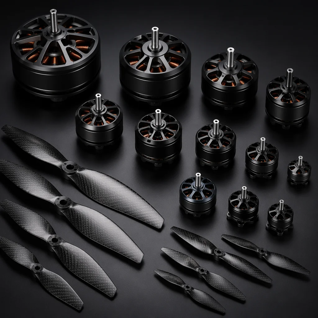
Conceptual UAV brushless motor and carbon fiber propeller visualization Concept illustration
Capabilities / Propulsion

Propulsion

Motors, propellers and powertrain matching — the thrust layer that converts electrical power into controlled lift, maneuverability and endurance.

RoleThrust Generation
Motor TypesBrushless Outrunner / Inrunner
Prop MaterialsCarbon Fiber / Plastic / Wood
Key MetricThrust-to-Weight Ratio
Overview

The motor and propeller are one system, not two choices.

Motor KV, stator volume and winding resistance define the electrical load. Propeller diameter, pitch and blade count define the aerodynamic load. Match them correctly and the system runs at peak efficiency. Mismatch them and you get excess heat, wasted battery capacity or insufficient thrust. Every other component decision — ESC rating, battery capacity, airframe strength — follows from this match.

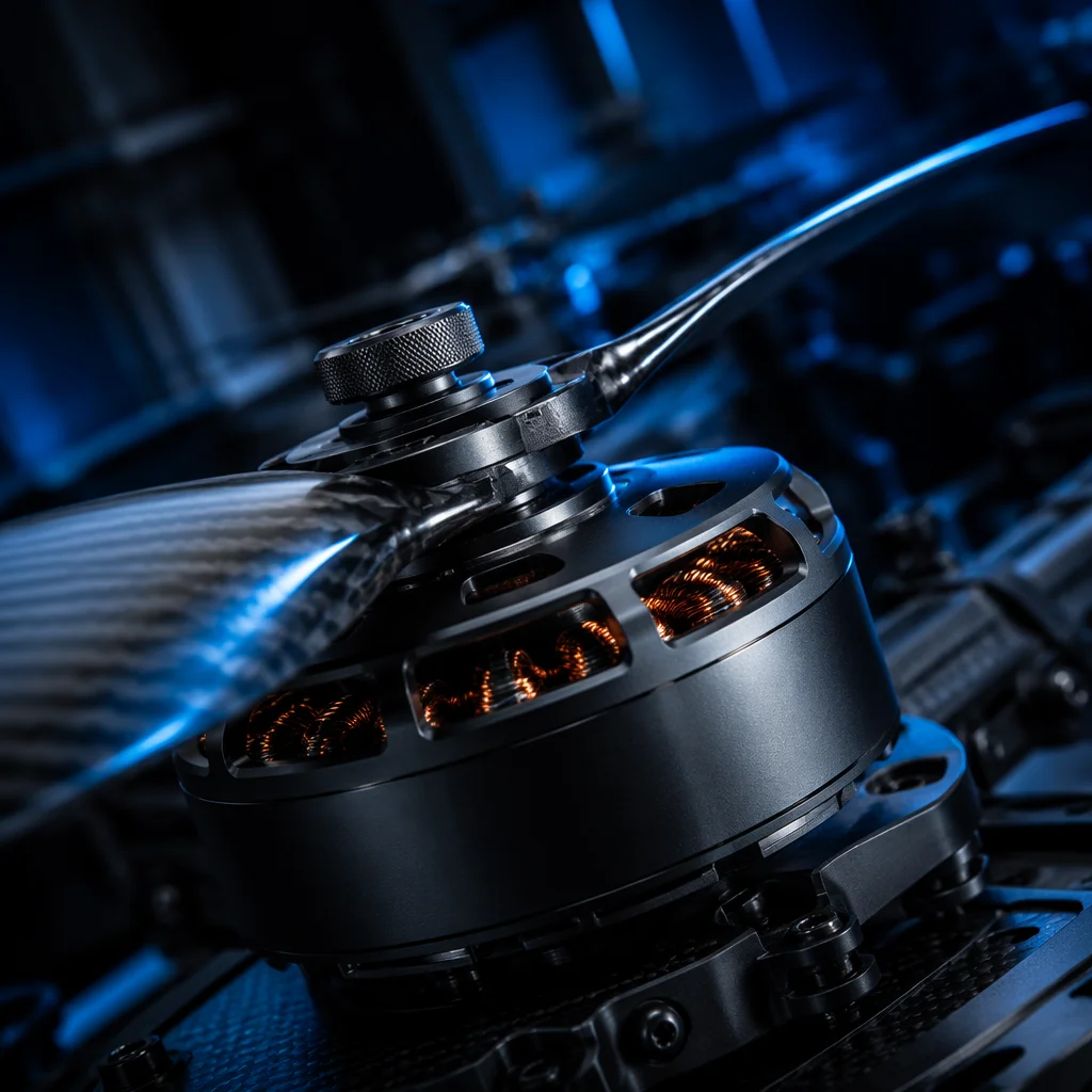
Brushless outrunner motor with carbon fiber propeller mounted on thrust test stand Concept illustration
Motor Types

Stator size, KV and efficiency define the motor's character.

Brushless outrunner motors dominate multi-rotor and fixed-wing UAV propulsion. Understanding the naming convention and performance parameters is the first step in selection.

Motor Sizing

Stator dimensions and naming

Motor names encode stator dimensions: a 2812 motor has a 28 mm stator diameter and 12 mm stator height. Larger stator volume handles more current and produces more torque — but adds weight. The relationship is not linear: a 2812 at 900 KV on 6S might produce 1.8 kg of thrust with a 9-inch prop, while a 4014 at 400 KV on 6S produces 3.5 kg with a 15-inch prop. Stator width contributes more to torque than height because torque scales with the square of radius.

  • 2207–2812 (3–7 inch)
  • 3510–4014 (7–15 inch)
  • 5010–6215 (15–22 inch)
  • 8318+ (24+ inch)
KV Rating

RPM per volt — but not the whole story

KV is RPM per volt with no load. Low KV (300–600) suits large propellers on high voltage — high torque, low RPM, efficient cruise. High KV (1800–2700) suits small propellers on lower voltage — high RPM, responsive throttle, shorter flight times. The practical KV choice is constrained by the battery voltage and propeller size: a 6S battery at 2400 KV would spin a 5-inch prop at over 50,000 RPM — exceeding the structural limits of most plastic propellers. KV must be selected in the context of both voltage and prop diameter.

  • Low KV: 300–600
  • Mid KV: 800–1200
  • High KV: 1800–2700
Efficiency Curves

Every motor has a sweet spot

Motor efficiency (grams of thrust per watt) peaks at 40–60% of max throttle for most outrunners. Above 80% throttle efficiency drops sharply as copper losses (I²R) dominate. For endurance-focused builds, the cruise throttle should sit in the motor's efficiency plateau. For agile builds, peak efficiency matters less than power-to-weight ratio and throttle response time. High-quality motors publish thrust tables across throttle positions with multiple propellers — the essential reference for matching.
Propeller Selection

Material, diameter, pitch and blade count.

The propeller converts motor torque into thrust. Four parameters define its performance envelope.

MaterialCarbon fiber: stiffest, lightest, most efficient — and most expensive. The standard for professional multi-rotors above 10-inch diameter. Plastic (polycarbonate/nylon composite): flexible, durable on impact, cheaper — acceptable below 7-inch where tip deflection is small. Wood: used on large fixed-wing props for vibration damping and tradition, less common in multi-rotor.
DiameterLarger diameter moves more air per revolution at lower RPM — more thrust per watt but slower response. A 15-inch prop at 5000 RPM produces roughly the same static thrust as a 10-inch at 8500 RPM, but with 30–40% less power draw. The trade-off is disc area: larger props need wider motor spacing and a bigger airframe.
PitchPitch (inches of forward travel per revolution, theoretically) determines the blade's angle of attack. Higher pitch (4.5–6.0 inch) gives higher top speed but loads the motor more at low RPM — higher current draw, more heat. Lower pitch (2.5–3.5 inch) gives better low-speed thrust and efficiency but lower maximum speed. Multi-rotors hovering at zero airspeed want lower pitch; fixed-wing cruising at 15–20 m/s can use higher pitch.
Blade countTwo-blade: most efficient in isolation. Three-blade: smoother, more thrust per disc area (important when prop diameter is constrained), slightly less efficient. Four-blade and above: used where disc loading is extremely high or for scale appearance — significant efficiency penalty. Most multi-rotors use 2-blade or 3-blade depending on whether diameter or smoothness is the priority.
Motor-Prop Matching

Methodology for finding the efficiency sweet spot.

Matching is an iterative process using manufacturer thrust tables — not guesswork.

Using thrust tables

Manufacturer data tables list thrust (g), current (A), power (W) and efficiency (g/W) for a motor at multiple throttle positions with specific propellers and voltages. Start with the aircraft's all-up weight, divide by the number of motors, multiply by 1.5–2.0 for hover headroom (hover at 50–65% throttle) — that is the target thrust per motor. Scan the thrust table for a prop that delivers that thrust at 50% throttle on the target voltage. The current at that throttle point tells you the ESC rating. The efficiency at that point tells you the expected flight time.

Common pitfalls

Over-propping: too large a propeller for the motor's current rating — the motor overheats and the ESC may desync or burn. Under-propping: too small a propeller leaves thrust on the table and forces high RPM to hover — wasting battery and generating unnecessary noise. Wrong voltage-KV combination: high KV on high voltage with even a moderate prop can pull destructive current. Always check that the propeller-motor-voltage triplet lands within the manufacturer's specified current range at full throttle, with headroom.

Thrust-to-Weight Guidance

How much thrust does your aircraft need?

Thrust-to-weight ratio (TWR) is the single number that defines flight performance. Different missions demand different TWR.

Hover-capable (TWR 1.5–2.0:1)Minimum for stable multi-rotor hover with control authority. Hover at 50–65% throttle leaves headroom for climb, wind correction and maneuver. Suitable for slow inspection platforms where endurance matters more than agility.
General purpose (TWR 2.0–3.0:1)Standard for professional multi-rotors. Hover at 33–50% throttle. Responsive climb, confident wind handling and reserve for payload variation. Most mapping, survey and light delivery platforms operate in this range.
Agile / heavy payload (TWR 3.0–4.0:1)For cinematography platforms that need rapid attitude changes, or heavy-lift platforms carrying payloads near the aircraft's structural limit. Hover at 25–33% throttle. Thermal management becomes critical because of the high installed power.
Fixed-wing (TWR 0.5–1.0:1)Fixed-wing aircraft generate lift from the wing, not just thrust. TWR below 1.0 is normal — the wing does the lifting, the motor provides forward speed. Hand-launch and climb performance set the minimum TWR; cruise efficiency sets the motor-prop match.
Vibration & Balancing

Unbalanced propulsion degrades everything.

Propeller and motor balance directly affect flight controller sensor noise, video quality and structural fatigue.

Propeller balancing

Even factory-balanced carbon fiber props can have residual imbalance — especially at larger diameters where a small mass asymmetry creates significant centrifugal force. A prop balancer (magnetic suspension type) and fine-grit sanding or tape on the lighter blade are the standard correction method. Dynamic balancing (balancing the hub as well as the blades) becomes important above 12-inch diameter where hub asymmetry is a noticeable vibration source.

Motor balance and mounting

Motor bell imbalance transfers vibration through the arm to the flight controller's IMU. Soft-mounting the FC with silicone grommets helps isolate gyro data from motor vibration, but does not fix the source. Motor bells should be checked for runout and balance — particularly on larger motors (35XX stator and above) where the rotating mass is significant. Prop adapter concentricity matters equally: an off-center prop creates a once-per-revolution vibration that is hard to filter.

Related Capabilities

Propulsion connects to power and structure.

Motor current defines the ESC. Propeller disc area shapes the airframe. Thrust loads flow through the structure.

ESC & Power

Motor current sizes the ESC

The motor-prop match determines current draw at every throttle position. ESC selection follows directly — the ESC must handle the motor's max current with 20–30% headroom at the operating voltage.

ESC & Power
Airframe

Motor mount and arm geometry

Thrust forces, motor mounting patterns and prop clearance define arm length, motor mount design and structural reinforcement requirements.

Airframe
Start With Thrust Requirements

Bring the aircraft weight and performance targets.

Tell us the all-up weight, desired thrust-to-weight ratio, preferred voltage and any diameter constraints. We will map the motor-prop match and verify it against your ESC and battery architecture.