
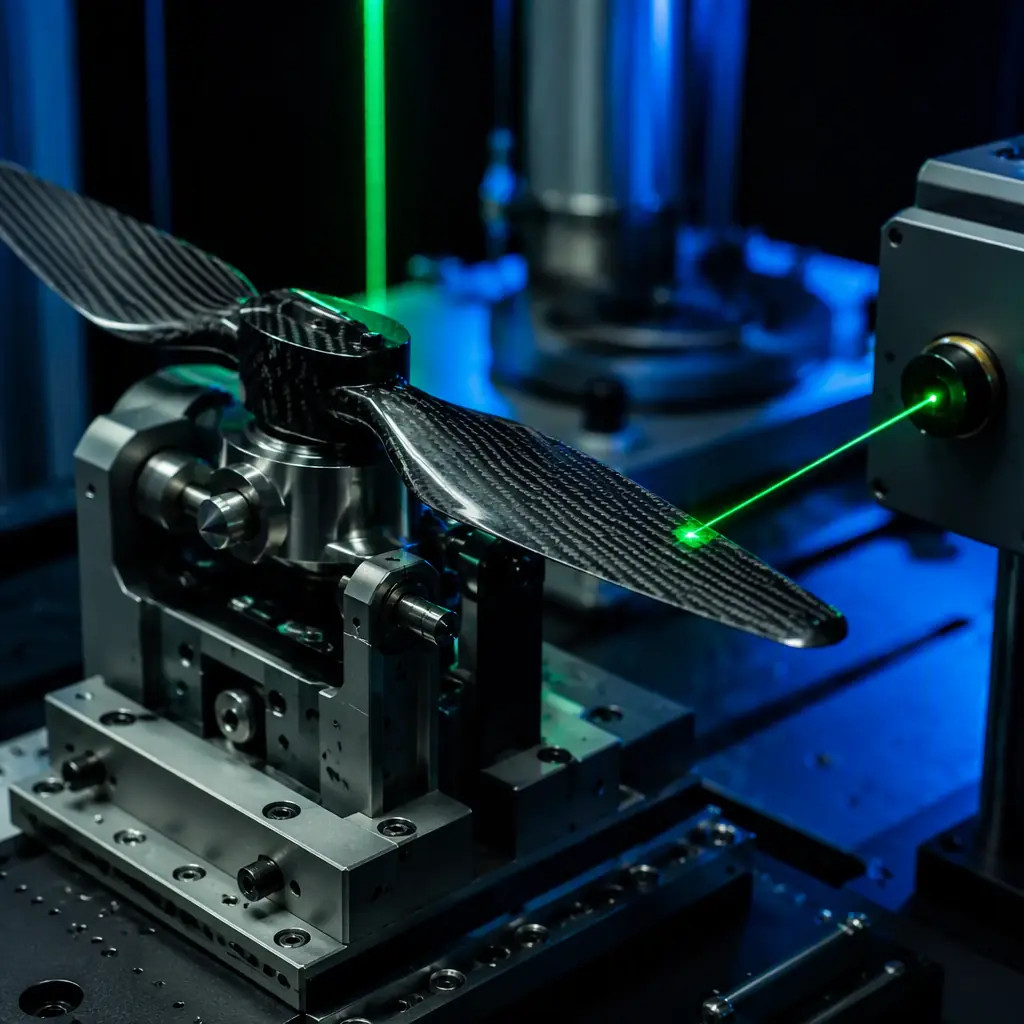
Propeller imbalance is the most common source of vibration in a multirotor or fixed-wing UAV, and it is also the cheapest to eliminate. The propeller selection guide covers how to choose diameter, pitch, blade count and material for a mission profile; this guide covers what happens after the propeller is chosen, how to specify its balance, measure the vibration it produces, and correct it in the field and at the factory. It sits alongside the propulsion testing and validation guide, which covers the thrust-stand and endurance testing that a complete propulsion system should pass before deployment.
Why propeller imbalance is a system problem, not a spinning part problem
Imbalance converts rotational energy into a sinusoidal force at the propeller's rotational frequency, and that force propagates through the motor mount into the airframe. The magnitude scales with the square of the rotational speed: the same residual imbalance that produces a barely measurable buzz at 2,000 RPM produces a destructive force at 6,000 RPM. For a two-blade propeller at 6,000 RPM the fundamental frequency is 100 Hz. Right in the range where a carbon fiber arm's first bending mode lives (typically 80–150 Hz for a 650 mm quadcopter arm, as the motor topology guide notes in its torque-ripple discussion). When the two coincide, the airframe amplifies rather than attenuates the vibration.
The system-level costs are measurable. The IMU sees the vibration as attitude noise, which degrades position hold and increases the correction effort the flight controller must apply, the safety and redundancy guide explains why a saturated IMU is a failure mode, not a nuisance. The camera and gimbal see it as image blur and servo wear. The motor sees it as accelerated bearing wear, and the ESC sees it as current ripple from the motor fighting the oscillation. Every one of those components has a vibration specification in its datasheet, and propeller imbalance is the single most likely reason the airframe exceeds them.
Static balance vs dynamic balance: which one your propellers actually need
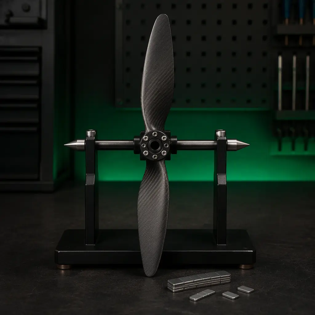
Balance comes in two forms, and the distinction decides what test equipment you need. Static balance is the center-of-gravity test: the propeller is placed on horizontal knife edges or a magnetic balancer, the heavy blade rotates to the bottom, and material is removed from (or added to) the light blade until the propeller rests in any position. Static balance removes the out-of-plane mass asymmetry but says nothing about how the mass is distributed along the hub axis.
Dynamic balance is the in-plane test: the propeller is spun on a balancing machine that measures the vibration at two bearing planes and computes the correction required in each plane. A propeller can pass static balance and still be dynamically unbalanced: for example, when both blades have equal mass but the mass is distributed differently along the span, producing a couple that only appears at speed. For a small UAV propeller the practical rule is simple: static balance is sufficient for propellers under roughly 250 mm diameter; dynamic balance is required above that, and for any propeller on a precision platform (mapping, survey, inspection) regardless of size. The mapping and survey components guide is the reference for why precision platforms are the demanding case: a centimetre-level RTK solution is meaningless if the IMU is vibrating through its noise floor.
 Concept illustration
Balance grades: what G2.5 and G6.3 mean for a UAV propeller
The ISO 1940-1 standard defines balance quality grades by the product of residual specific unbalance and rotational speed, the quantity G, expressed in millimetres per second. The relevant grades for propellers and rotors are G6.3 (typical for production propellers, fans and rotors with no special requirement) and G2.5 (for rotors with strict requirements, grinding machine spindles, aircraft propellers, and precision rotating assemblies). The residual eccentricity allowed at a given speed is e = G × 1000 / ω, where ω is the rotational speed in radians per second. At 6,000 RPM, ω = 628 rad/s, so G6.3 permits a residual center-of-gravity offset of about 10 µm and G2.5 permits about 4 µm.
Those numbers translate into procurement language. A 24-inch (600 mm) carbon fiber propeller of 25 grams balanced to G2.5 at 6,000 RPM carries a residual unbalance of roughly 0.1 g·mm. Below the resolution of most workshop scales, which is exactly why factory balance data matters more than a visual inspection. Nylon injection-molded propellers come out of the mold with blade-to-blade mass variation of ±3% in a production lot, as the propeller selection guide documents, and need post-molding balancing to reach a usable grade; carbon fiber propellers with consistent layup achieve ±0.5% and hold G2.5–G6.3 depending on the manufacturer's QC. When a supplier states a balance grade, ask for the test method and the per-unit data. A grade without a measurement report is a marketing claim.
Measuring vibration: from IMU logs to a balancing rig
Before balancing propellers, measure the vibration baseline. The aircraft's own telemetry is the cheapest instrument you already own. ArduPilot and PX4 log the IMU accelerometer at the full gyro rate; the ArduPilot vs PX4 guide covers the stacks, and both record the data you need. The procedure: hover the aircraft at cruise throttle in calm conditions, download the log, and inspect the FFT of the accelerometer axes. A sharp peak at the propeller rotational frequency (for example 100 Hz at 6,000 RPM on a two-blade propeller) is imbalance; a peak at the blade-pass frequency (200 Hz for a two-blade propeller at 6,000 RPM, 400 Hz for a four-blade) is an aerodynamic or tracking issue; broadband noise is usually motor bearing or ESC-related.
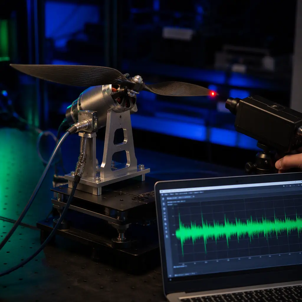
The acceptance threshold used by most flight controller vendors is vibration below 1 g RMS at the IMU, with 0.3–0.5 g as the target for smooth logs. If the baseline is above 1 g, or the rotational-frequency peak dominates the FFT, move to the bench: mount the motor on a thrust stand or rigid fixture, fit a calibrated accelerometer at the motor mount, and run the motor across the throttle range with a laser tachometer recording RPM. The propulsion testing guide describes the thrust-stand methodology this builds on. This measurement separates propeller imbalance from motor imbalance: spin the motor with no propeller and record the floor, then add the propeller. The delta at the rotational frequency is the propeller's contribution.
 Concept illustration
Where imbalance comes from: manufacturing, erosion, repair and mounting
Imbalance is not a binary defect; it is a property that drifts over the propeller's life, and a procurement team that treats it as a one-time factory check will be surprised by field results. The sources, in the order a propeller experiences them:
- Manufacturing. Mold parting lines, gate vestiges and inconsistent layup compression in composites create the initial imbalance. This is the source the balance grade covers. And the reason the acceptance test should be per-unit, not per-lot.
- Erosion and damage. Leading-edge erosion from particulate impact removes material unevenly, and the selection guide notes that erosion also triggers micro-cracks and UV degradation of the resin matrix. A propeller that was balanced at delivery can develop a gram-scale tip imbalance after a season of operations in dusty or sandy conditions.
- Repair and rework. Sanding, filling and re-tipping a damaged blade changes its mass distribution. Any repaired propeller must be rebalanced. And the repair itself should be documented, because the obsolescence management guide makes the broader point that field-modified components complicate the replacement and spares story.
- Mounting. The most common source of "imbalance" in the field is not the propeller at all: a collet that grips off-axis, a prop adapter with a bent shaft, a spinner that sits eccentrically, or debris under the mounting face. Always check the mounting hardware before rebalancing the propeller. The fix for a bent collet is a new collet, not tape on a blade.
- Moisture and temperature. Nylon absorbs moisture and changes mass and stiffness with humidity; composite propellers are far more stable. A nylon propeller balanced in a dry workshop can be measurably out of balance after a humid flight day, another argument for composite propellers on precision platforms.
Field balancing: the procedure that removes the last 90% of vibration
Factory balance gets a propeller to its grade; field balancing corrects the residual interaction of propeller, collet, motor and spinner as an assembly. The procedure that works in practice:
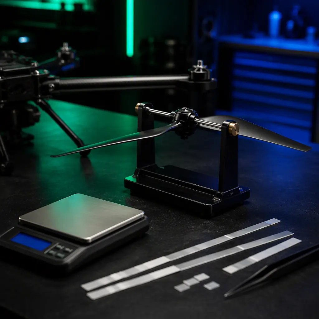
Step 1, static check. With the propeller off the aircraft, place it on a magnetic balancer or two knife edges. Mark the heavy blade (it rotates to the bottom), and add a small strip of tape to the light blade's tip or remove material from the heavy blade's back face, a few milligrams at a time. Repeat until the propeller rests at any angle. For a 24-inch carbon fiber propeller, the correction is typically 0.1–0.5 g.
Step 2, bench dynamic check. Mount the propeller and spinner on the motor, run up to cruise RPM on the instrumented fixture, and confirm the rotational-frequency peak dropped to the motor-only floor. If a peak remains at the rotational frequency with the propeller fitted but not without it, the residual is in the propeller/hub assembly, re-check the collet and hub runout first (a hub runout of 0.05 mm produces a significant imbalance force at 6,000 RPM), then re-balance the propeller as an assembly with the spinner fitted.
Step 3, in-flight verification. Re-hover and re-log the IMU. The acceptance criteria: the rotational-frequency peak is gone from the FFT, and overall vibration is below the 0.3–0.5 g target. Log the result per aircraft, because the fleet management guide shows how a per-aircraft vibration log turns a one-time fix into a maintenance trigger. When the vibration peak grows back, the propeller or its mounting has changed and it is time to inspect.
 Concept illustration
Resonance and the vibration budget: coupling, modes and margins
Balance removes the forcing function; resonance decides whether the airframe amplifies what remains. Every airframe has structural modes, the first bending mode of a carbon fiber arm, the torsional mode of a folding arm latch, the mounting resonance of a gimbal or antenna mast, and the design discipline is to keep the propeller's rotational and blade-pass frequencies away from those modes across the operating throttle range. The motor topology guide gives the concrete example: a 3.36 kHz torque ripple from a high-ripple motor couples weakly into a 650 mm quadcopter whose arm modes sit at 80–150 Hz, but a 100 Hz propeller fundamental sitting directly on an arm mode is a different story.
The practical vibration budget has four layers: isolate (motor mounts and gimbal isolators with the correct durometer, the thermal management guide makes the related point that soft mounts also change heat paths, so the isolation choice is coupled to the thermal design), absorb (damping material on the arm, tuned mass dampers on the gimbal), filter (the flight controller's low-pass filters on the IMU, the sensor fusion guide covers the filtering architecture), and remove the source (balance the propeller). A propeller balanced to G2.5 removes the largest source; the other three layers then have a manageable input to work with instead of a saturated one.
The procurement specification: balance grade, measurement and acceptance
The specification that closes the loop with suppliers has five clauses, each with a verification method:
1. Balance grade. State the ISO 1940-1 grade per propeller size, G2.5 for propellers above 250 mm diameter and for precision-platform applications, G6.3 as the minimum acceptable for small production propellers. Verification: the supplier's per-unit balance report with the test RPM.
2. Balance test method. State whether static balance is acceptable (propellers under 250 mm) or dynamic balance is required (above 250 mm, and all precision-platform propellers). Verification: the test equipment description in the QC documentation, cross-checked against the electronics manufacturing quality guide for how QC documentation should be structured.
3. Blade-to-blade mass tolerance. State the maximum blade-to-blade mass difference per propeller size, ±0.5% for composite propellers on precision platforms, ±3% for nylon production propellers with post-molding balancing. Verification: the per-lot mass measurement data.
4. Acceptance testing. State the acceptance vibration threshold at the motor mount, below 1 g RMS at the IMU in hover, 0.3–0.5 g target, and the test procedure (motor-only floor vs propeller fitted). Verification: the test report from the propulsion testing program.
5. Field re-balance support. State whether the supplier provides balance data for replacement and repaired propellers, and the process for re-balancing repaired units. Verification: the repair and replacement documentation in the warranty and RMA terms.
The specification is only as good as the measurement it references. A procurement team that specifies G2.5 but accepts visual inspection has written a requirement it cannot verify; a team that specifies G2.5 and audits the balance report against its own bench measurement has closed the loop, and the supplier evaluation checklist is the framework for making that audit part of the vendor score.
Explore custom engineering Back to Blog
EMS Drone manufactures balanced propulsion assemblies under one roof, from component sourcing through production test. If you are specifying for a build, see the full capability set and the tolerances we hold.
Continue Reading
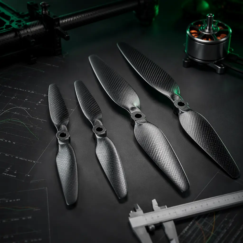
UAV Propeller Selection Guide
Diameter, pitch, blade count and material. The selection methodology that determines what balance grade a given propeller can actually hold.
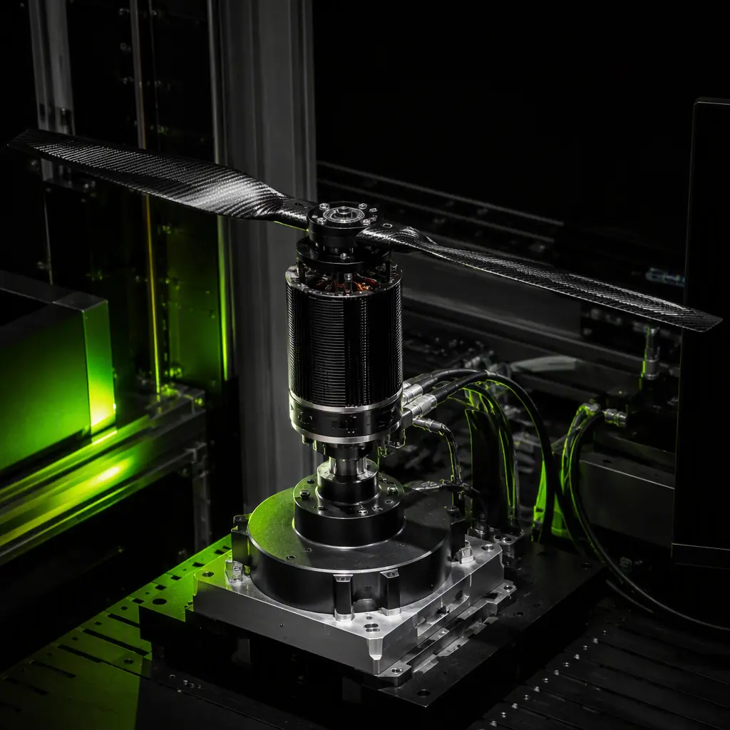
UAV Propulsion Testing & Validation
Thrust stand, thermal endurance and propeller efficiency measurement, the test program that turns a balance specification into verified performance.
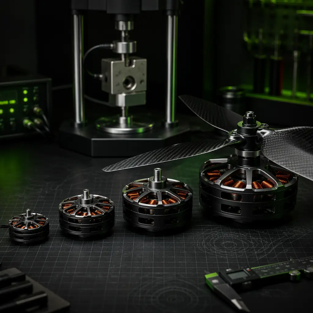
UAV Brushless Motor KV Selection
How motor KV sets the operating RPM range. And therefore the balance grade and blade-pass frequency your propeller specification must reference.
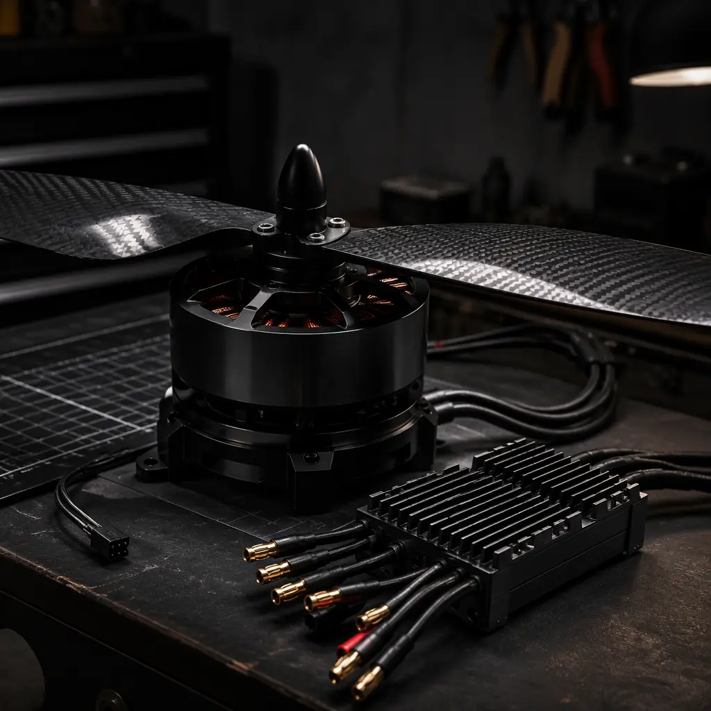
UAV Heavy-Lift Propulsion Design
Large propellers at high disc loading, where imbalance forces scale fastest and dynamic balance becomes non-negotiable.
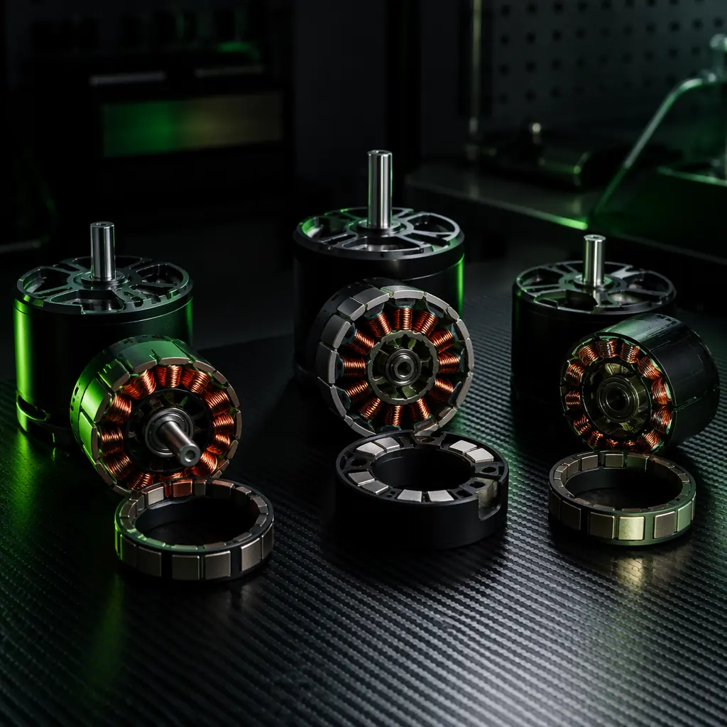
UAV Motor Topology: BLDC vs PMSM vs PMAC
Torque ripple and harmonic content from the motor side, the other half of the coupled vibration problem this guide addresses.