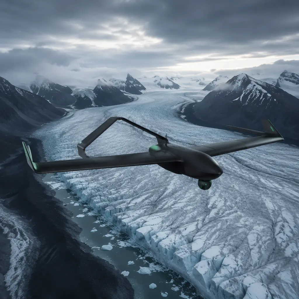
Environmental monitoring is the fastest-growing non-military UAV application segment by mission hours flown. The global fleet of environmental research UAVs logged approximately 4.2 million flight hours in 2025, up from 1.1 million in 2021 — a 40% compound annual growth rate driven by climate research funding, biodiversity monitoring mandates and the replacement of manned aircraft surveys with UAV platforms that cost 85–95% less per flight hour. But the environmental UAV component supply chain is fundamentally different from every other UAV segment. An inspection drone that loses GNSS lock returns to launch and the mission is rescheduled. An environmental monitoring drone that loses GNSS lock over a melting ice shelf 60 km from the base station is gone. The procurement standard for environmental monitoring UAV components is endurance first, resilience second, and performance third — endurance because the mission radius demands it, resilience because the deployment environment will break anything that is not overbuilt for it, and performance because the sensor data must be good enough to publish in a peer-reviewed journal.
The environmental monitoring component chain has four interacting constraints that do not appear together in any other UAV application. The airframe must provide 90–180 minutes of endurance in a platform light enough to be carried to the deployment site — which may be a 6-hour hike from the nearest road. The communications link must maintain telemetry and low-bandwidth data relay at ranges of 30–80 km without cellular infrastructure, using frequency bands that are legal in the deployment country and that do not interfere with the sensor payload. The power system must operate in ambient temperatures from −20°C (alpine glacier) to +50°C (desert ecology plot), with solar augmentation that adds 15–30% to the endurance but introduces MPPT electronics that add failure modes. And the sensor payload — a multi-parameter air quality monitor, a water sampling mechanism, an acoustic recorder, a thermal camera — must be electrically isolated from the propulsion system to prevent motor EMI from corrupting sensor readings at the parts-per-billion level. These four constraints are coupled: adding solar panels increases endurance but increases drag, which requires more thrust, which draws more current, which requires a larger battery, which increases weight, which reduces endurance. The component decisions must be made as a system, not as a list.
Airframe and endurance architecture: fixed-wing, hybrid VTOL and lighter-than-air
The airframe decision for environmental monitoring is primarily an endurance decision, but the deployment context constrains the viable configurations. A fixed-wing platform with a 2.5-meter wingspan and a 3–5 kg all-up weight delivers 90–150 minutes of flight time on a 6S Li-Ion pack, covering 60–100 km of transect at 15–18 m/s cruise speed — the standard configuration for wildlife surveys, vegetation mapping and coastal erosion monitoring. But a fixed-wing requires a launch and landing zone: a 30–50 meter clear strip for hand-launch and belly-landing, or a catapult launcher and parachute/net recovery system that adds 1.5–2.5 kg to the logistics load. When the deployment site is a research vessel with a 5 × 5 meter helideck or a forest clearing with no approach path, a hybrid VTOL platform — a fixed-wing with four lift rotors for vertical takeoff and landing — provides the endurance of a fixed-wing with the deployment flexibility of a multirotor, at a 15–25% endurance penalty from the lift-rotor battery and motor mass that are dead weight in forward flight.
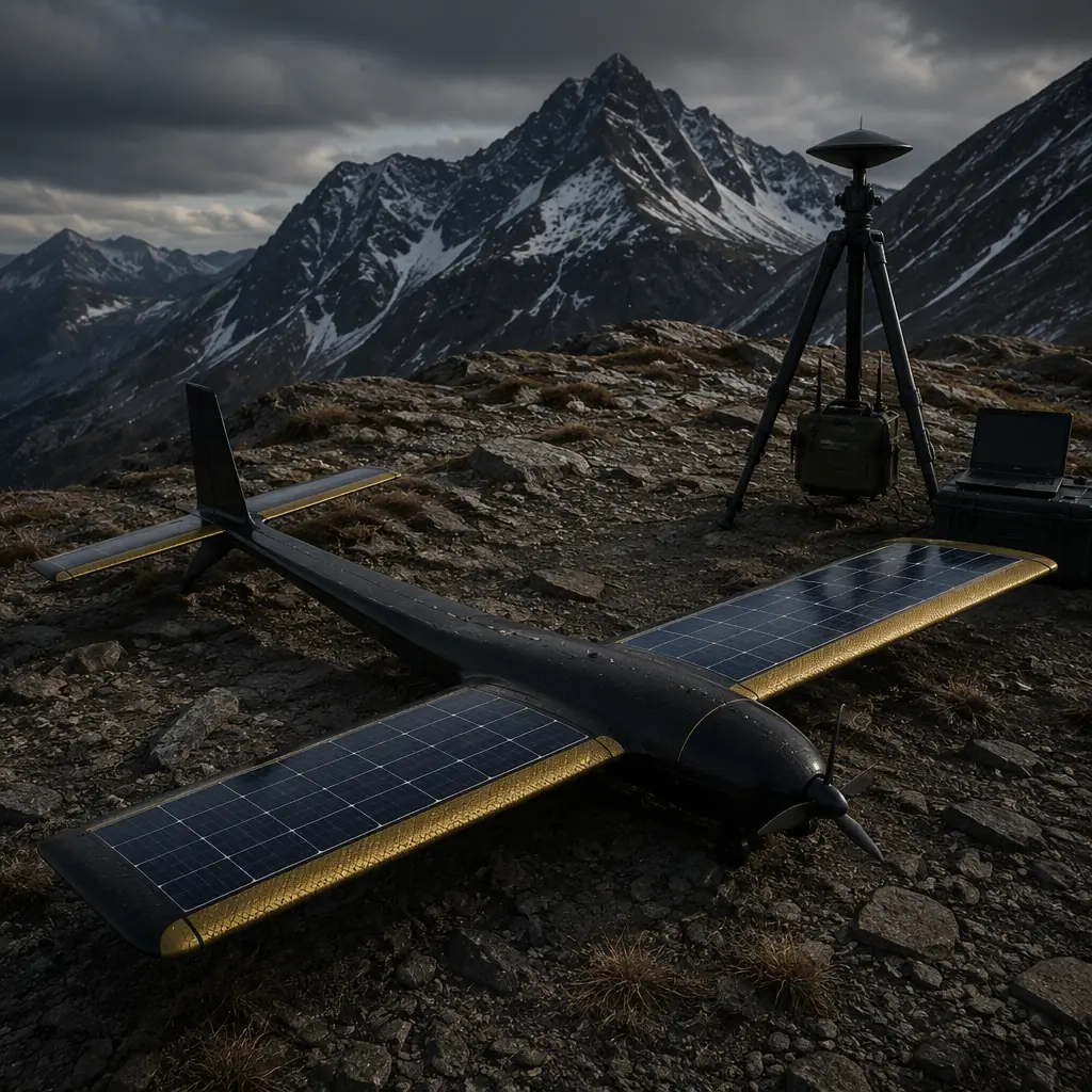
Fixed-wing airframe materials for field deployment. The airframe must survive repeated hand-launches (3–5 g longitudinal acceleration) and belly-landings on unprepared surfaces — grass, gravel, sand, snow — without structural damage. A carbon fiber wing with a foam core and a Kevlar or fiberglass leading-edge strip provides the impact resistance for 200+ belly-landings on gravel. The Kevlar strip at the leading edge (approximately 150 g/m², applied as a wet layup over the carbon fiber) absorbs the abrasion and point-impact of gravel and frozen ground landings without cracking the underlying carbon laminate. Without the Kevlar strip, a carbon fiber leading edge develops delamination cracks within 20–30 gravel landings, reducing the wing's bending stiffness by 15–25%. The fuselage should be a carbon fiber monocoque with a removable payload bay floor — not a permanently bonded structure — to allow sensor reconfiguration in the field without specialized tools. The tail surfaces should be removable (nylon wing bolts or quick-release pins) for transport in a standard Pelican case; a fixed-wing platform that cannot be broken down to fit in airline checked baggage (62 linear inches, 158 cm) is useless for international research deployments.
 Concept illustration
Lighter-than-air for stationary monitoring. For applications that require persistent station-keeping — atmospheric profiling above a fixed point, methane leak monitoring over a pipeline, wildlife observation at a waterhole — a tethered lighter-than-air platform (helium aerostat or kytoon) provides continuous flight endurance measured in days, not hours. A 5–8 m³ helium envelope lifts a 3–5 kg sensor payload to 100–300 meters AGL, with the tether providing both power (via a copper conductor pair in the tether cable) and data (via fiber in the same cable). The tether station — a ground-level winch with a slip-ring for continuous 360° rotation — requires approximately 500 W of power from a generator, solar array or vehicle inverter. The aerostat's envelope material must be a polyurethane-coated polyester or Tedlar laminate with a helium permeability below 0.5 L/m²/day/atm to require reinflation less than once every 14 days. For the airframe and structure trade-offs that apply across UAV configurations, the UAV airframe materials guide covers the carbon fiber, aluminum and composite selection methodology.
Remote telemetry: satellite, LoRa and mesh architectures
The communications challenge for environmental monitoring is not bandwidth — most environmental sensors produce data at 1–100 kbps, easily within the capacity of even low-data-rate links — but range, reliability and regulatory compliance in the deployment country. A marine mammal survey UAV operating 80 km offshore has no cellular coverage and no line of sight to a ground station. An Amazon canopy-monitoring multirotor has no cellular coverage and no line of sight to anything except the leaves 2 meters above it. The communications architecture must be designed for the worst-case scenario in the deployment environment, not the average.
Satellite communications for beyond-line-of-sight telemetry. For deployments beyond 30 km from any ground infrastructure, satellite-based telemetry is the only viable option. The Iridium Short Burst Data (SBD) service provides global coverage with 340-byte messages at approximately 0.5–1.0 second latency, at a cost of roughly USD 0.05–0.10 per message — adequate for transmitting aircraft position, battery voltage, airspeed and a single sensor reading every 10–30 seconds. An Iridium 9603 or 9602 modem weighs 12–30 grams and draws 1.5 W in transmit, easily integrated into a fixed-wing UAV's payload bay with a ceramic patch antenna on the upper fuselage. For higher-bandwidth applications — transmitting a 0.5 MB image from a multispectral camera once per transect — the Iridium Certus service (L-band, 176 kbps) or a Starlink Mini terminal (Ku-band, 100+ Mbps, 1.1 kg, 25–40 W) provides the throughput, but at a weight and power cost that only the largest fixed-wing platforms (5+ kg AUW, 6S or higher) can carry. The Starlink terminal's 25–40 W power draw during transmission represents approximately 15–25% of the cruise power budget of a 3-meter fixed-wing UAV — a non-trivial endurance penalty that must be modeled before committing to the architecture.
LoRa and sub-GHz mesh for distributed sensor networks. When multiple UAVs or ground sensors operate in the same deployment area — a wildfire monitoring campaign with three aircraft and 20 ground-based weather stations — a LoRa mesh network at 868/915 MHz provides local data relay at ranges of 10–30 km (air-to-ground) with 0.3–50 kbps data rates at power consumption below 100 mW per node. A Semtech SX1276 or SX1262 transceiver module (USD 8–15, 2 grams) integrated with a simple wire or helical antenna provides the physical layer. The mesh architecture means each UAV relays data from the ground sensors to the base station, so the aircraft at the edge of the network can communicate with the base station through intermediate nodes. The LoRa modulation's spreading factor (SF7–SF12) trades data rate against range: SF7 delivers 5.5 kbps at 2–5 km, SF12 delivers 0.3 kbps at 15–30 km in clear air. For environmental monitoring campaigns that combine UAV and ground sensors, the UAV RF communication systems guide covers the frequency band selection and antenna placement for sub-GHz links.
Power systems for extreme environments and solar augmentation
The power system of an environmental monitoring UAV must deliver consistent energy across an ambient temperature range that spans 70°C — from the −20°C of a winter glacier deployment to the +50°C surface temperature of a desert ecology plot. Standard LiPo packs lose 20–30% of their rated capacity at −10°C and experience accelerated aging above 45°C. The battery chemistry, pack configuration, thermal management and solar augmentation strategy form a single integrated power architecture decision.
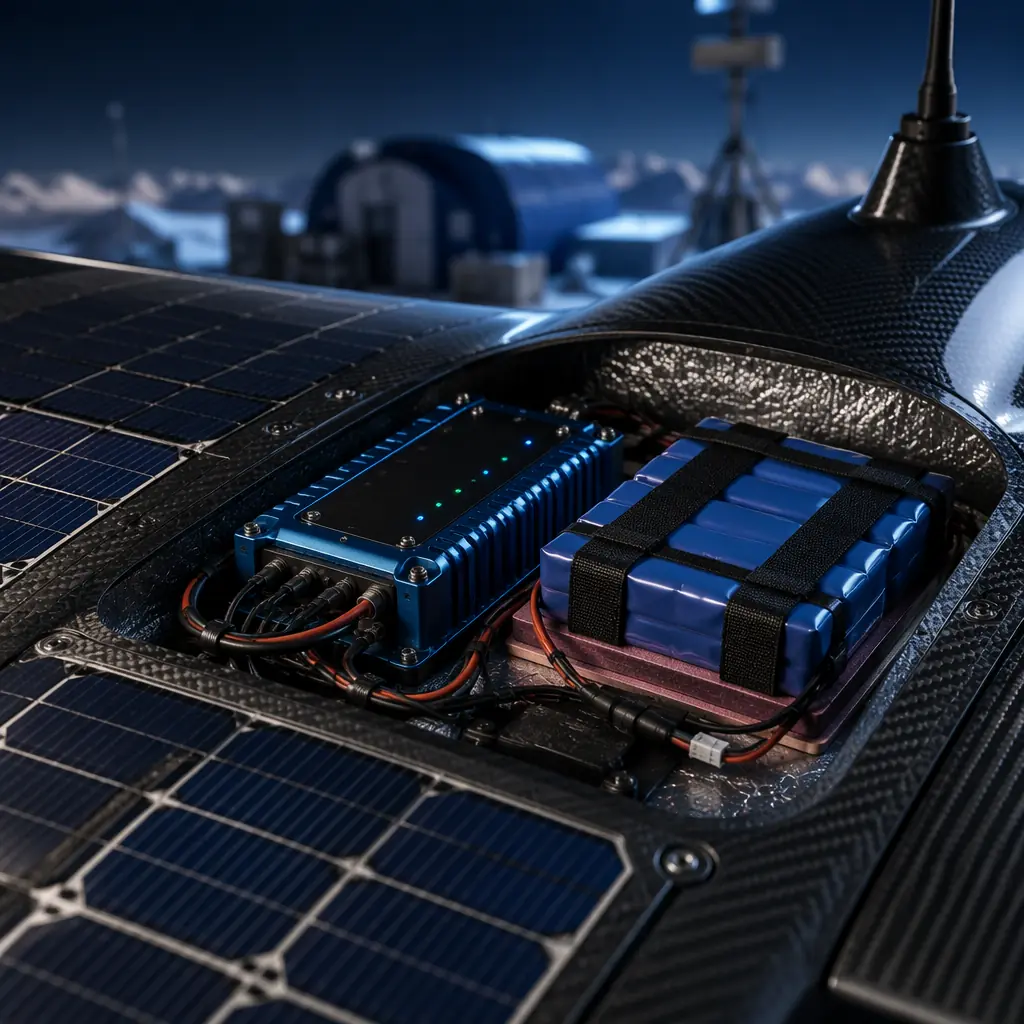
Battery chemistry for temperature extremes. Li-Ion cells (18650 or 21700 form factor, NMC or NCA chemistry) outperform LiPo packs in environmental monitoring applications for two reasons: wider operating temperature range and higher energy density. A Samsung 50E or Molicel P42A 21700 cell delivers 210–230 Wh/kg at 25°C and retains approximately 75–80% of that capacity at −10°C, compared to 55–65% for a typical LiPo pouch cell. At the high end, Li-Ion cells tolerate 50°C ambient with approximately 5–8% accelerated capacity fade per 100 cycles, compared to 10–15% for LiPo. The trade-off is discharge rate: a 21700 Li-Ion pack in a 6S4P configuration (22.2 V nominal, 16–20 Ah) delivers 30–40 A continuous (1.5–2C), which is adequate for a fixed-wing UAV cruising at 8–12 A, but not for a multirotor hovering at 40–60 A. For multirotor environmental monitoring platforms, a LiPo pack in a thermally insulated enclosure — closed-cell foam or aerogel blanket, 5–10 mm thickness — with a resistive heating pad (5–10 W, thermostatically controlled to maintain the pack above 5°C) recovers 85–90% of the capacity loss at −20°C ambient, at the cost of 5–10 W of continuous heating power drawn from the pack itself.
 Concept illustration
Solar augmentation design. Wing-mounted solar panels — SunPower Maxeon or similar mono-crystalline cells with 22–24% efficiency — can add 15–30% to the endurance of a fixed-wing environmental monitoring UAV flying in clear-sky conditions at latitudes below 50°. On a 2.5-meter wingspan platform with 0.35 m² of wing area, a solar array of 20–24 cells (each 125 × 125 mm, 3.5–4.0 W per cell at AM1.5) delivers 70–96 W peak, or approximately 35–50 W averaged over a flight in partly cloudy conditions with the sun angle varying as the aircraft turns. At a cruise power draw of 120–180 W for a 3–4 kg fixed-wing UAV, the solar array provides 20–40% of the cruise power — not enough for indefinite flight, but enough to extend a 90-minute endurance to 110–130 minutes. The MPPT (maximum power point tracking) charge controller must be a dedicated module — not the BMS's built-in charging circuit — with an efficiency above 92% across the input voltage range of the solar array (8–12 V for a 12-cell series string). The MPPT output connects to the battery's charge input through a blocking diode that prevents reverse current flow when the solar array is in shade. For the battery selection methodology and BMS configuration for multi-cell packs, the UAV battery and power management guide provides the cell-level selection framework.
Sensor payload integration and EMI isolation
The sensor payload of an environmental monitoring UAV is a collection of instruments that collectively cost 3–10× the airframe — a Picarro CRDS greenhouse gas analyzer at USD 40,000, a LI-COR CO₂/H₂O gas analyzer at USD 25,000, a multi-spectral camera at USD 5,000–15,000, or a water sampling mechanism that lowers a Niskin bottle on a winch from a hovering multirotor. The sensor integration challenge is not mechanical mounting — the sensors bolt to a standard payload rail — but electromagnetic isolation from the propulsion system. When a 12S ESC switches 40 A at 24 kHz, the radiated EMI from the motor wires induces 5–50 mV of noise on any unshielded signal cable within 30 cm of the power wiring, and a CO₂ analyzer measuring concentration changes of 0.1 ppm is looking for a signal change of 0.1 μV from its detector — five orders of magnitude below the EMI noise floor.
EMI isolation for precision sensors. The sensor payload must be isolated from the propulsion system at three levels: physical separation, electrical isolation and signal-domain filtering. Physical separation means the sensor compartment is located at least 30 cm from the ESCs and motor power wiring — in the nose of a fixed-wing fuselage or on an isolated sub-frame below a multirotor — with the intervening structure acting as a partial Faraday cage if it is carbon fiber (carbon fiber provides approximately 20–40 dB of shielding at 1–100 MHz, depending on the weave density and the contact resistance between the fiber tows and the ground plane). Electrical isolation means the sensor payload is powered from a separate battery or a galvanically isolated DC-DC converter — not from the same bus as the propulsion system — to prevent motor current ripple from appearing on the sensor power rail. A 5 V or 12 V isolated DC-DC converter (CUI, Traco or Murata, 1–3 W, >1,500 V isolation) costs 10–20 grams and eliminates the conducted EMI path between the propulsion battery and the sensor electronics. Signal-domain filtering means all analog sensor outputs pass through a differential amplifier with a common-mode rejection ratio above 80 dB at the noise frequency (24–48 kHz for most ESC PWM frequencies), and all digital sensor interfaces use differential signaling (RS-485 or CAN bus) rather than single-ended (I²C, UART) for cable runs longer than 20 cm.
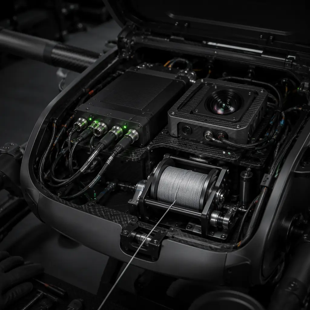
Water sampling mechanism integration. A multirotor UAV that hovers above a lake, river or coastal water body and lowers a sampling bottle on a winch requires two specialized components: a corrosion-resistant winch mechanism and a payload release that does not contaminate the sample. The winch uses a brushless motor (200–300 KV, similar to a gimbal motor) driving a 30–50 mm diameter spool through a 5:1–10:1 belt reduction, with a Spectra or Dyneema braided line (0.5–0.8 mm diameter, 20–30 kg breaking strength) that is chemically inert — nylon line absorbs water and introduces contamination. The sampling bottle is a standard Niskin or Van Dorn bottle (1–2 liter capacity) with PTFE end caps and silicone O-rings — no metal parts below the waterline to avoid trace metal contamination. The mechanical release is a servo-actuated pin that triggers the bottle's spring-loaded end caps when the bottle reaches the target depth (measured by a pressure sensor in the winch head, 0.1 dbar resolution). The entire winch-and-bottle assembly weighs 400–800 grams and draws 15–30 W during descent and ascent, manageable for a multirotor with 3–5 kg payload capacity. For the mechanical and electrical integration standards that apply across payload types, the UAV payload integration guide covers the interface design and EMI management methodology.
 Concept illustration
Flight controller and autonomy for unattended missions
An environmental monitoring UAV that flies a pre-programmed transect for 90 minutes with no human interaction needs a flight controller that handles GNSS loss, wind compensation, airspeed management and autonomous landing without a ground-station operator making decisions. The ArduPilot ecosystem (Pixhawk Cube Orange+, CUAV X7, or Holybro Durandal running ArduPlane 4.x) provides the autonomy framework for fixed-wing environmental monitoring, and ArduCopter 4.x for multirotor platforms. The flight controller's 8 kHz IMU and 1 kHz control loop are standard across these platforms. The differentiating firmware parameters for environmental monitoring are the failsafe behaviors and the airspeed management strategy.
Failsafe strategy for beyond-recovery-range flight. The standard ArduPilot failsafe behavior — enter Return-to-Launch (RTL) mode on loss of RC signal or GNSS — is inadequate when the aircraft is 60 km from the launch point and has 30 minutes of battery remaining for a 60-minute return flight. The correct failsafe configuration for environmental monitoring is a tiered strategy: on loss of RC signal but with valid GNSS and adequate battery for the return flight plus a 20% reserve, execute RTL at the most efficient cruise speed (not maximum speed, which depletes the battery faster per kilometer traveled). On loss of GNSS but with RC signal, enter a loiter pattern at the last known position and the current altitude, transmitting the last known coordinates over the telemetry link, and wait for the operator to issue a manual recovery command. On simultaneous loss of RC and GNSS — the worst case — execute a pre-programmed forced landing at the nearest waypoint designated as a forced-landing zone in the mission plan, using dead-reckoning from the last known GNSS position and the IMU's attitude and heading reference. The forced-landing zone waypoints must be surveyed in advance and stored in the mission file; they should be clear areas (roads, dry lake beds, beaches) with a 50-meter radius and no obstacles above 2 meters. For the flight controller and ESC integration that enables precise autonomous flight, the flight controller and ESC matching guide covers the protocol and failsafe configuration parameters.
Airspeed management for fixed-wing endurance. The endurance of a fixed-wing UAV is maximized when the aircraft flies at its best L/D (lift-to-drag ratio) speed — not its minimum power speed and not its maximum range speed. For a typical 3–4 kg environmental monitoring airframe with a 2.5-meter wingspan, the best L/D speed is approximately 15–17 m/s indicated airspeed (IAS), at which the airframe produces approximately 12–15 N of drag and requires 180–250 W of propulsion power. The flight controller must maintain this target airspeed using a pitot-static airspeed sensor (not GPS ground speed, which includes wind) — a digital airspeed sensor such as the MS4525DO or DLVR-L10D with 0.5 m/s accuracy at 10–50 m/s is adequate. The autopilot's TECS (Total Energy Control System) algorithm adjusts throttle to maintain the target total energy (kinetic + potential) and elevator to control the energy distribution between speed and altitude, enabling the aircraft to maintain the best-L/D airspeed while climbing or descending through thermals, wind shear and density altitude changes. A pitot tube heater (5–10 W, thermostatically controlled to maintain the pitot above 5°C) is mandatory for flights in visible moisture or at altitudes where the ambient temperature is below freezing — a blocked pitot tube produces an airspeed reading of zero, which causes the autopilot to command full throttle in an attempt to increase airspeed, depleting the battery in minutes.
Procurement checklist: 6 component decisions for environmental monitoring UAVs
These six component decisions form the minimum validation gate before ordering hardware for an environmental monitoring UAV. Each is tied to a specific deployment requirement — survival in the target environment and data quality sufficient for peer-reviewed research output.
1. Airframe endurance verification. Calculate the required endurance from the mission radius, the time-on-station at the survey area, and a 20% reserve for headwinds. Verify that the airframe's endurance at the best-L/D cruise speed meets or exceeds this requirement at the maximum deployment altitude (reduced air density = reduced propeller efficiency, approximately 5–10% thrust loss per 1,000 meters above sea level). Validate with a flight test at the deployment site or a site with equivalent density altitude: the aircraft must complete the full mission profile and land with ≥15% battery remaining.
2. Communications link budget for the deployment range. Calculate the link budget for the maximum planned range between the aircraft and the ground station, including antenna gain, cable loss, free-space path loss and a 10 dB fade margin. If the link budget does not close with terrestrial radios (LoRa, 900 MHz, 2.4 GHz), plan for satellite telemetry. Validate by ground-testing the telemetry link at the maximum range before the first flight.
3. Battery thermal management for the deployment temperature. Characterize the battery pack's capacity at the lowest expected ambient temperature. If the capacity loss exceeds 20% at the deployment temperature, add thermal insulation and a heating pad. Validate by cold-soaking a test pack at the deployment temperature for 4 hours, then discharging at the expected cruise current: the delivered capacity must meet the mission requirement with a 15% reserve. For the cell-level specification, see the battery management guide.
4. Sensor EMI validation. Measure the noise floor of each sensor's analog output with the propulsion system operating at cruise power — motors running, ESCs switching at their PWM frequency. The peak-to-peak noise induced on the sensor signal must be below 10% of the sensor's specified resolution. If the noise exceeds this threshold, add physical separation, electrical isolation or both. For the shielding and grounding standards, see the payload integration guide.
5. Failsafe configuration audit. Verify that the flight controller's failsafe parameters are configured for the mission profile: RTL altitude above the highest terrain obstacle on the return path, forced-landing waypoints at surveyed clear areas within 20 km of the survey zone, and a battery failsafe threshold that triggers RTL with enough reserve for the return flight plus a 20% margin calculated at the worst-case headwind. For the FC parameter mapping, refer to the FC and ESC matching article.
6. Solar augmentation cost-benefit analysis. If the deployment involves flights longer than 90 minutes or repeated flights from the same launch point with limited battery logistics, evaluate the endurance gain from wing-mounted solar panels against the weight, cost and complexity penalty. At current cell prices (USD 1.5–2.5 per cell for SunPower mono-crystalline), a 20–24 cell wing array costs USD 40–80 and adds 150–250 grams including the MPPT controller and wiring — a cost of approximately USD 0.20–0.40 per additional minute of flight endurance for a 3–4 kg fixed-wing platform. For the economic analysis framework, see the build vs. buy cost analysis.
Explore research solutions Back to Blog
Continue Reading
UAV RF Communication Systems
LoRa, 900 MHz, 2.4 GHz and satellite link budgets for remote environmental deployments.
Battery & Power Management
Li-Ion cell selection, cold-weather thermal management and solar MPPT integration.
UAV Payload Integration Guide
EMI isolation, galvanic separation and sensor mounting standards across payload types.
Airframe Materials Guide
Carbon fiber, Kevlar leading edges and foam-core wing structures for field durability.
Flight Controller & ESC Matching
ArduPilot failsafe tiers and TECS airspeed management for autonomous long-range flight.