
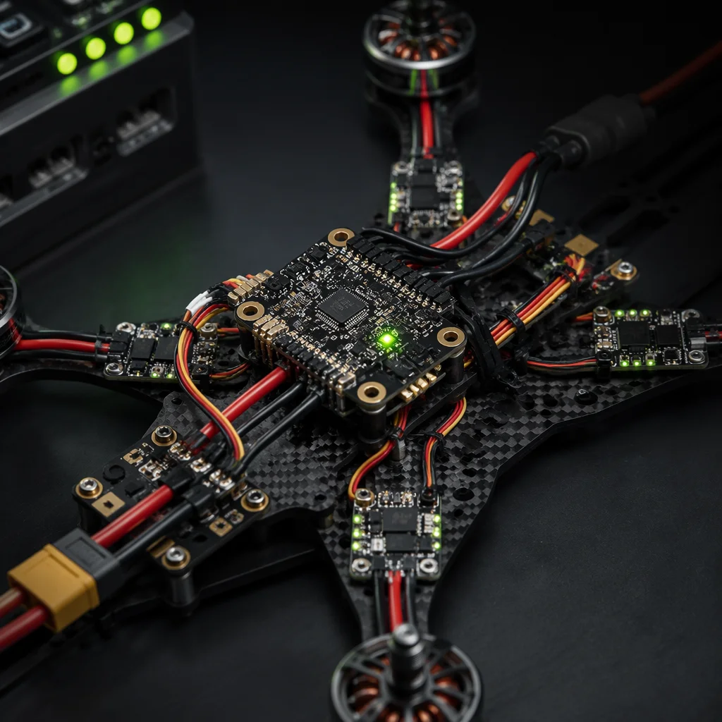
Flight controllers and electronic speed controllers sit at the center of how a UAV senses, decides and converts commands into thrust. Selecting them independently is a common source of late-stage rework: wiring changes, firmware limits, unexpected heat or motor behavior that does not match the airframe.
Start with the shared interfaces
Before comparing feature lists, document the interfaces that bind the control and power layers:
- Communication protocol . How the controller issues motor commands and receives feedback
- Voltage architecture . Pack voltage, distribution and what the ESC and peripherals expect
- Current and thermal context . Continuous and peak demand relative to mounting and airflow
- Firmware and configuration path . Parameters, calibration steps and bench-check expectations
These are system questions. Answering them early reduces the chance that a “good” board or ESC becomes the wrong fit for the rest of the stack.
Coordinate motors and mechanical fit early
ESC selection is incomplete without motor and propeller context. Kv, prop load, mounting geometry and wire routing all influence whether the electrical path stays within a workable envelope. Likewise, controller placement affects sensor noise, cable length and access for service.
Treat the propulsion decision as a chain: controller ↔ ESC ↔ motor ↔ prop ↔ structure. Changing any link should reopen the compatibility review for the adjacent links.
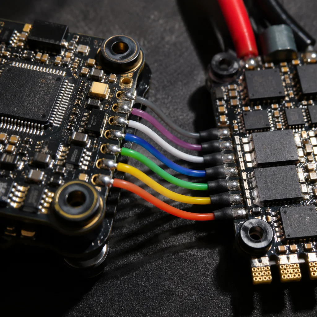 Concept illustration
A practical matching sequence
- Capture mission priorities that drive thrust and endurance assumptions
- Lock or shortlist the voltage and protocol constraints
- Review ESC topology and motor options against those constraints
- Confirm controller I/O, telemetry and firmware alignment
- Plan bench checks for direction, power path and parameter sanity before flight
Exact product options and ranges should be reviewed against your technical brief. Published catalogs alone rarely capture harness, thermal or firmware edge cases.
Education, not a deployment story
This note is industry education for teams building or sourcing UAV stacks. It does not claim a specific customer outcome, certified configuration or production capacity. Use it to structure the conversation, then validate with your mission and interface data.
Signal Paths That Matter
The physical link between flight controller and ESC is the DShot or PWM signal wire, but the engineering link goes deeper. The flight controller's PWM update rate, the ESC's firmware response time, and the motor's electrical time constant form a control loop that must be stable across the entire throttle range.
On multirotor platforms, the loop runs at 1 kHz or higher, which means signal latency of even a few milliseconds shows up as visible oscillation or poor yaw response. This is why matching is not just about connector compatibility. It is about selecting an ESC firmware that responds fast enough for the flight controller's chosen protocol, and a motor that does not exceed the ESC's current rating during aggressive maneuvers.
For industrial platforms carrying payloads, we recommend documenting the full signal chain in the integration spec: protocol, update rate, ESC firmware version, and motor winding. Teams that write this down once eliminate an entire class of field failures that otherwise surface only after deployment.
Common Mismatch Failure Modes
The most common field failure is the silent mismatch: a flight controller that defaults to a conservative PWM rate paired with an ESC that expects a faster protocol. The aircraft flies, but with degraded responsiveness that pilots often describe as "soft" or "laggy." Diagnosing this requires checking the actual configured protocol on both ends, not just the datasheet.
Current rating mismatches are the second most common issue. An ESC rated for continuous current will tolerate brief peaks, but a motor that pulls above that peak during hard braking or sudden throttle changes will eventually destroy the ESC's MOSFETs. The fix is margin: select an ESC rated at least 1.5x the motor's peak current draw.
Firmware version drift is the third. ESC firmware updates change timing and response characteristics, and a flight controller tuned for an older version may oscillate or lose sync after an update. Distributors who publish firmware compatibility matrices reduce these field issues substantially and position themselves as engineering partners rather than parts suppliers.
The bottom line: matching is an engineering discipline, not a paperwork exercise. Document the signal chain, verify current margins, and control firmware versions across the fleet. Teams that treat matching as a first-class design activity see measurable improvements in flight quality and a sharp reduction in field failures.
Bench-testing the pair before airframe assembly
Most ESC and flight-controller mismatches surface at the bench, not in flight, and they are far cheaper to catch there. Wire the pair on a test stand with a current sensor and a bench power supply, then verify that throttle commands, bidirectional communication, and the expected current draw all line up with the data sheet before the kit goes into the airframe. Logging a short hover in a safe enclosure exposes thermal limits and timing drift that a static bench check can hide. This ten-minute bench pass routinely prevents a fielded unit that behaves erratically at full load.