
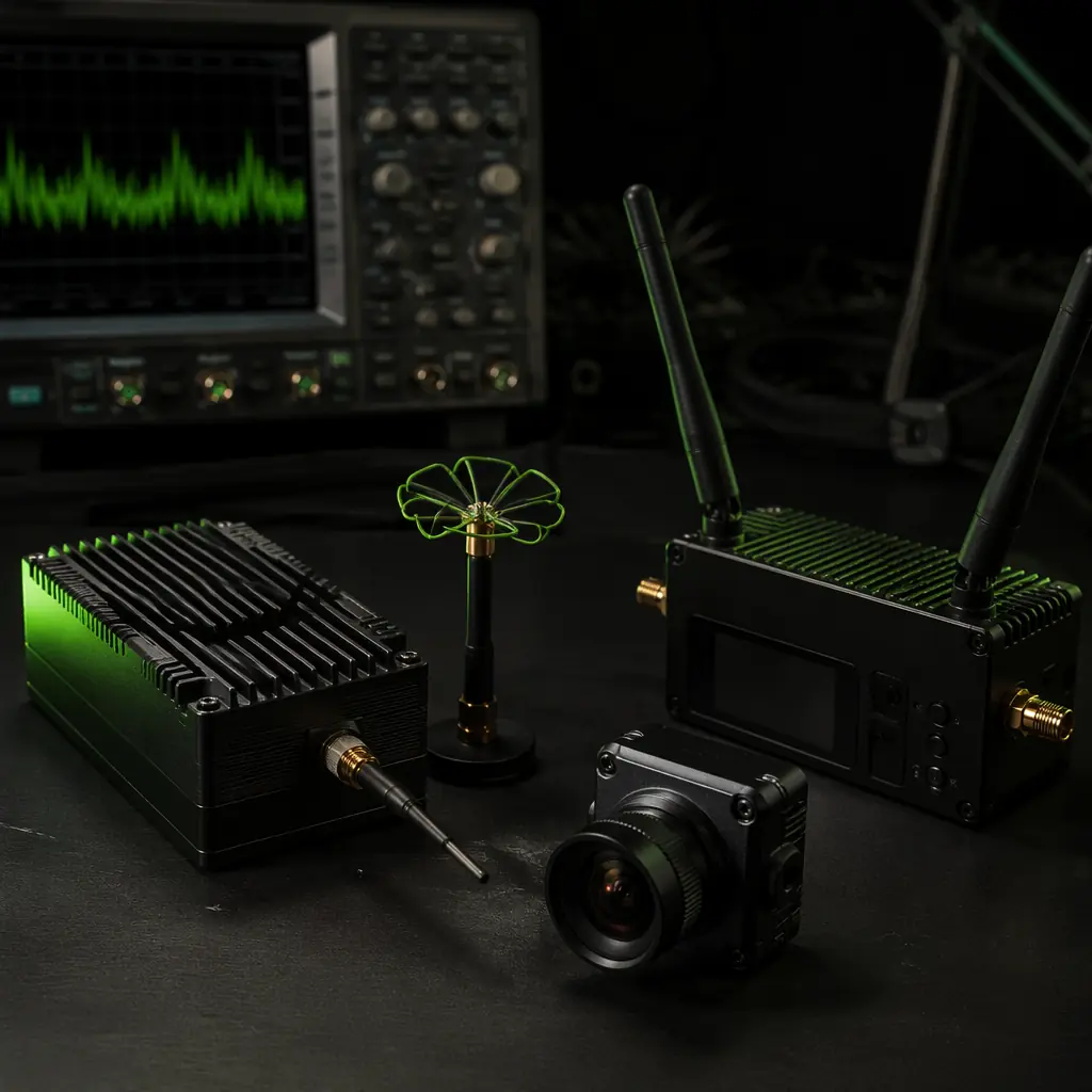
The industrial UAV video downlink market has bifurcated into two technology families that share almost no common infrastructure. Analog transmission — the 40-year-old technology that originated in broadcast television and was adapted to consumer FPV racing — uses FM-modulated NTSC or PAL video over the 1.2 GHz, 2.4 GHz or 5.8 GHz ISM bands, with fixed latency of approximately 15–35 milliseconds from camera sensor to display, a resolution ceiling of approximately 720 × 576 pixels (PAL, effectively 0.4 megapixels) and no forward error correction — if the signal degrades, the image degrades progressively from noise to snow, with no cliff effect. Digital transmission — the technology family that DJI, HDZero and Walksnail have commercialized for the UAV market since 2019 — uses H.264 or H.265 compressed video over 5.8 GHz with OFDM modulation, adaptive bitrate, forward error correction and a resolution range from 720p to 1080p (HDZero at 720p, Walksnail and DJI at 1080p, approximately 0.9 to 2.1 megapixels), but with variable latency of 22–50 milliseconds (HDZero at the low end, DJI at the high end) and a cliff effect — when the signal-to-noise ratio drops below the forward error correction threshold, the image disappears entirely rather than degrading gracefully. The procurement decision is not "which is better" — it is "which failure mode is acceptable for this mission, and which resolution-latency trade-off maximizes the mission's operational effectiveness."
This article builds a video downlink selection methodology from the procurement team's perspective. It starts with the physics of video transmission — frequency, modulation, coding gain and link budget — and progresses through the three digital ecosystems available to industrial UAV integrators: DJI (the closed ecosystem with the highest resolution and the highest latency), HDZero (the open-architecture system with the lowest digital latency) and Walksnail (the middle ground with 1080p resolution and moderate latency). It addresses the analog option — why analog video still dominates for specific mission profiles where predictable degradation is more valuable than high resolution — and provides the frequency band selection criteria for 1.2 GHz, 2.4 GHz and 5.8 GHz in the context of different regulatory environments (FCC Part 15 in the United States, CE in Europe, the SRRC in China). It covers the antenna selection — linear vs circular polarization, omnidirectional vs directional, the diversity receiver architecture and the MIMO systems that are beginning to appear in the industrial video downlink market. And it provides a procurement checklist that the team can use to specify a video downlink that matches the payload camera, the airframe's antenna mounting constraints, the mission's range and latency requirements and the operational environment's RF noise floor. For the broader RF communication system — including the telemetry link, the command-and-control link and the GNSS receiver — the UAV RF communication systems guide covers the end-to-end RF architecture. For the payload integration that determines what the video downlink is transmitting — the gimbal, the camera sensor and the video encoding pipeline — the UAV payload integration guide covers the sensor-to-downlink interface.
The video link budget: why range is never just about transmitter power
A 1 W (30 dBm) video transmitter does not deliver twice the range of a 500 mW (27 dBm) transmitter — it delivers approximately 1.4 times the range, because radio propagation in free space follows an inverse-square law: doubling the distance reduces the received power by a factor of four (6 dB), and doubling the transmitter power increases the received power by only 3 dB. The link budget — the accounting of every gain and loss between the transmitter's output connector and the receiver's input connector — is the procurement team's primary tool for predicting whether a given video downlink configuration will deliver usable video at the mission's maximum range. The link budget equation for a video downlink is:
Received Power (dBm) = Transmitter Power (dBm) + Transmitter Antenna Gain (dBi) + Receiver Antenna Gain (dBi) − Free-Space Path Loss (dB) − Cable Loss (dB) − Connector Loss (dB) − Polarization Mismatch Loss (dB) − Fading Margin (dB)
The free-space path loss at 5.8 GHz over 5 km is approximately 122 dB — and that number dominates the link budget. A 1 W transmitter (30 dBm) with a 3 dBi omnidirectional transmitting antenna and a 13 dBi directional patch receiving antenna, after 122 dB of path loss and 3 dB of combined cable and connector losses, delivers approximately 30 + 3 + 13 − 122 − 3 = −79 dBm to the receiver's RF front end. An analog video receiver typically requires −85 to −90 dBm for a usable image (defined as a signal-to-noise ratio of approximately 25 dB, at which snow is visible but the image is interpretable) — so the link closes with a margin of 6–11 dB, which is adequate for line-of-sight operation but may be insufficient if the UAV banks and the transmitting antenna's polarization rotates relative to the receiving antenna (a 20 dB polarization mismatch loss from a 90-degree rotation between a vertically polarized transmitting antenna and a horizontally polarized receiving antenna). A digital video receiver operating in the DJI ecosystem requires approximately −95 dBm for the minimum modulation and coding scheme (MCS0, the most robust but lowest-data-rate modulation), which provides a larger link margin, but at the maximum range the digital system will drop to MCS0 — at which point the video bitrate is approximately 5–8 Mbps, sufficient for a 720p image at 30 fps but not for 1080p. The procurement team must specify the minimum acceptable video quality at the maximum range — not just at the bench — and must verify that the link budget closes at that quality level with the specified antennas, cable losses and a 10 dB fading margin for multipath and antenna orientation variation during flight.
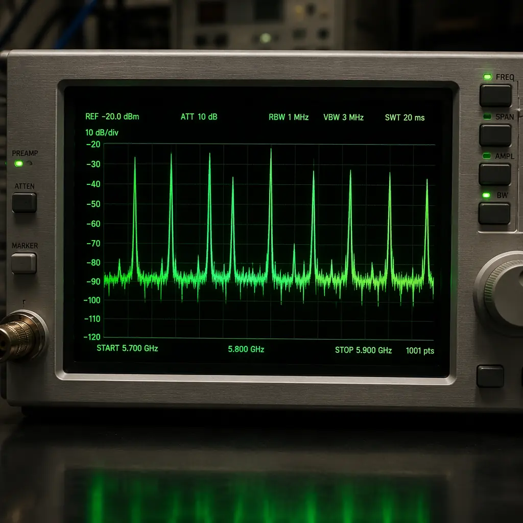
The choice of frequency band is the single largest determinant of the link budget. At 1.2 GHz, the free-space path loss over 5 km is approximately 108 dB — 14 dB less than at 5.8 GHz — which means a 1.2 GHz system with the same transmitter power and antenna gains will deliver approximately 5 times the received power (14 dB = a factor of approximately 25, but the 1.2 GHz band is noisier — the ambient RF noise floor in urban environments is typically 10–15 dB higher at 1.2 GHz than at 5.8 GHz because of broadcast television harmonics, amateur radio and industrial equipment — so the effective range advantage is approximately 3–4 times, not 5 times). However, 1.2 GHz video transmitters are illegal for airborne use in most jurisdictions without a specific license (the 1.2 GHz band is allocated to aeronautical radio navigation in many countries, and a UAV transmitting on 1.2 GHz can interfere with DME and TACAN ground navigation aids), and the antennas are approximately 3–4 times larger than 5.8 GHz antennas for the same gain (a 5 dBi 1.2 GHz antenna is approximately 12 cm in diameter; a 5 dBi 5.8 GHz antenna is approximately 3 cm). For the vast majority of industrial UAV applications, 5.8 GHz is the default band because of its global license-exempt status, its compact antenna form factor and its compatibility with all three digital ecosystems. The 2.4 GHz band — shared with Wi-Fi, Bluetooth and the UAV's own 2.4 GHz control link — is generally not recommended for video downlinks because the band is congested and the simultaneous operation of a 2.4 GHz video transmitter and a 2.4 GHz control receiver on the same UAV creates mutual interference that neither system's front-end filtering can fully suppress. The 868/915 MHz bands (ISM, license-exempt in Europe and North America respectively) offer even lower path loss — approximately 99 dB at 5 km for 868 MHz — but the available bandwidth (typically 200–500 kHz per channel) is inadequate for video (which requires 5–20 MHz of bandwidth depending on the modulation) and these bands are better suited to telemetry and command-and-control as covered in the UAV RF communication systems guide.
 Concept illustration
Digital ecosystems compared: DJI, HDZero and Walksnail
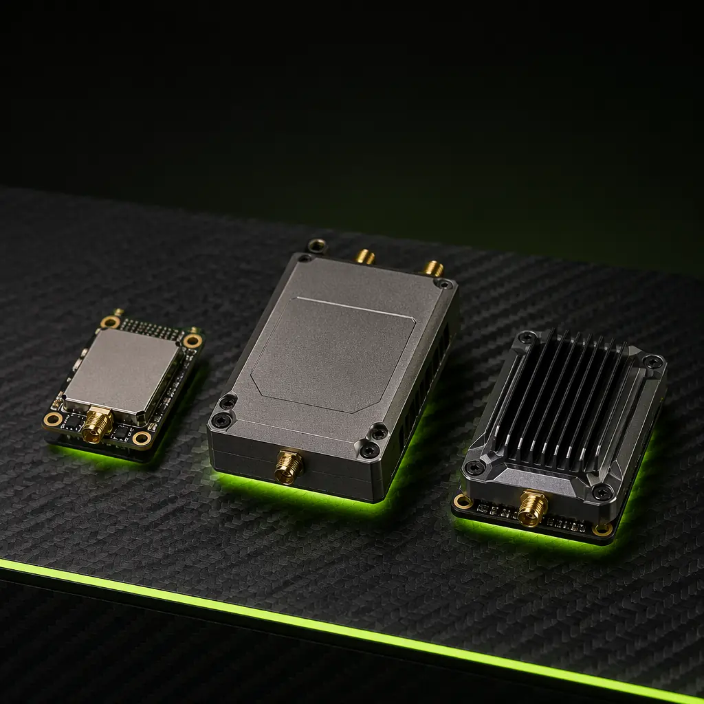
Three digital video ecosystems dominate the industrial UAV market as of 2026, and each represents a different engineering philosophy about the resolution-latency trade-off. The procurement team's selection among them is a decision about which of the two variables — resolution or latency — is the primary constraint for the mission, and which ecosystem's integration model (closed and proprietary vs open and interoperable) aligns with the UAV's avionics architecture.
DJI Digital FPV (O3 Air Unit and successors). DJI's system delivers 1080p video at up to 120 fps (or 4K at 60 fps in the O4 variant) with a variable latency of 28–50 milliseconds depending on the channel quality, the bitrate (25–50 Mbps) and the distance (the system adaptively reduces bitrate as the signal weakens, which increases compression latency). The image quality at close range — sharp, color-accurate, with minimal compression artifacts — is the best of the three ecosystems by a significant margin, which is why DJI dominates applications where the remote pilot or the payload operator needs to identify fine details: power-line inspection (spotting a frayed conductor strand at 50 meters), search and rescue (identifying a person in foliage from altitude) and cinematography (where the video feed is the product, not just a piloting aid). However, the DJI ecosystem is closed: the air unit, the camera and the ground unit are a matched set, and the protocol is proprietary — the procurement team cannot integrate a third-party camera with a DJI air unit, cannot decode the DJI video stream with a third-party receiver and cannot modify the system's channel selection or bitrate allocation algorithm. For an industrial UAV integrator who needs an open-architecture video downlink that can be integrated with a custom camera, a custom gimbal controller and a custom ground station — such as a defense UAV where the camera is an export-controlled thermal imager and the video must be routed through an onboard encryption module before transmission — DJI is a non-starter. Additionally, DJI's latency is the highest of the three ecosystems because of the H.265 encoding pipeline — the encoder buffers multiple frames to exploit temporal redundancy in the video, which improves compression efficiency but adds 15–25 milliseconds of encoding latency — which makes the system unsuitable for high-speed, close-proximity maneuvering where the pilot needs sub-30-millisecond latency to avoid obstacles.
HDZero. HDZero takes the opposite approach: it sacrifices resolution (720p at 60 fps or 540p at 90 fps) to achieve the lowest digital latency available — 22–28 milliseconds from camera sensor to display, comparable to analog latency. The system achieves this by using a lightweight, intra-frame-only compression scheme (each frame is compressed independently, without reference to previous or future frames, eliminating the frame buffer that adds latency in H.264/H.265 encoders) and by transmitting at a fixed bitrate of approximately 25 Mbps regardless of channel quality — there is no adaptive bitrate, so the image quality is constant until the signal drops below the forward error correction threshold, at which point the image freezes. The open-architecture approach — HDZero publishes the protocol, and multiple third-party manufacturers produce compatible receivers and video transmitters — makes the system attractive for industrial UAV integrators who need to customize the video pipeline but who can accept the 720p resolution limit. The fixed latency and the open protocol make HDZero the preferred choice for BVLOS inspection UAVs where the latency budget is tight (a UAV flying at 20 m/s covers 0.5 meters in 25 milliseconds, which is the difference between a near-miss and a collision with a bridge cable) and for multi-UAV operations where multiple HDZero video streams can be received and decoded by a single ground station with software-defined radio hardware — a capability that DJI's closed protocol does not support.
Walksnail Avatar. Walksnail occupies the middle ground: 1080p resolution at 60 fps or 720p at 120 fps, with variable latency of 28–40 milliseconds and adaptive bitrate from 25 to 50 Mbps. The image quality is close to DJI at short range (slightly more compression artifacts in high-motion scenes because of a less sophisticated motion estimation algorithm in the encoder), and the latency is close to HDZero at 720p (approximately 28 milliseconds at 720p/120 fps, rising to approximately 38 milliseconds at 1080p/60 fps because of the larger frame buffer required for 1080p encoding). The Walksnail ecosystem is partially open — the protocol is not published, but the air unit outputs standard MIPI CSI camera interfaces, which allows integration with third-party cameras (unlike DJI), and the ground unit outputs HDMI, which allows integration with any HDMI-capable monitor or video encoder. For the industrial UAV procurement team, Walksnail represents the best compromise for missions that require 1080p resolution for detailed inspection but that can accept 35–40 milliseconds of latency — a category that covers the majority of inspection, surveying and monitoring applications.
 Concept illustration
Analog video: why it still matters for industrial UAVs
Analog video, for all its resolution limitations, has three characteristics that keep it in the industrial UAV procurement conversation. First, the latency is fixed and deterministic: the camera sensor outputs an NTSC or PAL analog video signal with a frame time of 16.7 milliseconds (NTSC, 60 Hz) or 20 milliseconds (PAL, 50 Hz), and the FM modulator adds approximately 1–2 milliseconds of group delay — so the total glass-to-glass latency (camera sensor to display) is 18–35 milliseconds, with zero frame-to-frame variation. A digital system's latency varies from 22 to 50 milliseconds depending on the bitrate, the channel quality, the frame type (I-frame vs P-frame vs B-frame in H.264/H.265) and the decoder's buffer state — a variation that can cause the pilot to perceive the UAV's response as inconsistent, overshooting on some inputs and undershooting on others, because the control loop's effective delay is changing from frame to frame. For high-speed, close-proximity inspection — a power-line UAV flying at 15 m/s with 5 meters of clearance from the conductors, where the pilot makes a control input every 200–300 milliseconds — a 10-millisecond variation in latency represents a 5% variation in the control loop's phase margin, which is enough to cause pilot-induced oscillation in some airframes.
Second, analog video degrades gracefully: as the signal weakens, the image transitions from clear to slightly grainy to moderately snowy to unusable — and at every stage, the pilot can see that the signal is degrading and can decide whether to turn back, climb higher or adjust the antenna orientation. A digital system provides no such warning — the image is perfect until it freezes, and the freeze may occur with less than 1 dB of margin above the forward error correction threshold, which can be crossed by a momentary antenna null caused by a bank angle change of 10–15 degrees. For BVLOS operations where the pilot cannot visually verify the UAV's attitude, the graceful degradation of analog video provides a safety margin that the digital cliff effect does not — and some industrial UAV operators run a low-resolution analog camera in parallel with a high-resolution digital system specifically to provide this graceful-degradation backup. The RF communication architecture for multi-link UAVs — which must coordinate the frequency assignments, the antenna placement and the mutual interference between the video, telemetry and control links — is covered in the UAV RF communication systems guide. The integration of the video downlink with the autopilot for BVLOS operations — where the autopilot must continue the mission if the video link is lost — is covered in the remote ID and BVLOS compliance guide.
Third, analog video is the lowest-cost option by a wide margin: a complete analog FPV system — camera, video transmitter, antenna and receiver — costs approximately $60–150 at the component level, compared to $250–600 for a digital system. For a UAV integrator building a fleet of 50 inspection UAVs, the $200–450 per-unit cost difference represents $10,000–22,500 in total procurement cost — which may be justified if the digital system's higher resolution reduces the inspection time per structure by 15–20% (because the inspector can identify defects in the live video feed rather than reviewing the recorded footage afterward), but which must be accounted for in the program budget. For the procurement cost analysis framework that weighs component cost against operational efficiency — including the total cost of ownership over a 3–5 year fleet lifecycle — the UAV component build vs buy guide provides the methodology.
Antenna selection and diversity: the overlooked half of the link budget
The antennas on a UAV video downlink are responsible for approximately 10–20 dB of the link budget — which is more than the difference between a 200 mW transmitter and a 1 W transmitter (7 dB). A poorly selected or poorly mounted antenna can reduce the effective range by 50–70% compared to the system's potential, and the procurement team must specify the antenna type, the polarization, the gain, the radiation pattern and the mounting location as part of the video downlink specification — not as an afterthought.
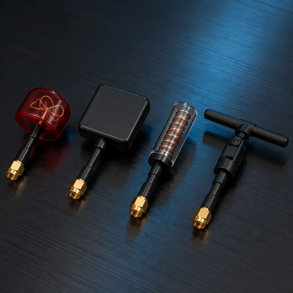
Polarization. Linear polarization — where the electric field oscillates in a single plane — is simple and low-cost, but it is vulnerable to polarization mismatch: if the transmitting antenna (vertical) and the receiving antenna (horizontal, because the ground station operator tilted the antenna) are 90 degrees apart, the received power drops by 20–30 dB — effectively erasing the link. Circular polarization — where the electric field rotates as the wave propagates — eliminates the polarization mismatch problem (a right-hand circularly polarized receiving antenna will receive a right-hand circularly polarized signal with approximately 3 dB of loss regardless of the relative orientation of the two antennas) at the cost of a 3 dB penalty (a circularly polarized antenna's gain is 3 dB lower than a linearly polarized antenna of the same size, because half the transmitted power is in the orthogonal polarization component). For industrial UAVs where the airframe banks, pitches and yaws continuously during flight, circular polarization on both ends of the link is the standard recommendation.
Diversity reception. A diversity receiver uses two or more antennas — typically one omnidirectional and one directional, or two directional antennas pointed in different directions — and selects the antenna with the strongest signal on a frame-by-frame basis (for analog) or combines the signals from both antennas using maximum-ratio combining (for digital systems that support it). The diversity gain — the effective improvement in signal-to-noise ratio compared to a single antenna — is typically 3–6 dB when the antennas are spaced at least one wavelength apart (approximately 5 cm at 5.8 GHz), which translates to a 30–50% range extension. The procurement specification should require diversity reception for any industrial UAV video downlink operating beyond 1 km — the additional cost of a second antenna and a diversity-capable receiver module is approximately $20–40, and the range extension is effectively free in terms of transmitter power and spectrum usage.
 Concept illustration
Video downlink procurement checklist
The following checklist is a procurement-ready summary of the video downlink specification items that must be verified before placing a purchase order. Each item includes the verification method and the acceptable range or value for industrial UAV applications.
Transmission system. Technology type — analog (FM, NTSC/PAL), digital (DJI O3/O4, HDZero, Walksnail Avatar) or hybrid (dual analog+digital feed). Frequency band — 5.8 GHz (recommended for global license-exempt operation), 1.2 GHz (requires license in most jurisdictions, larger antennas) or 2.4 GHz (generally not recommended due to Wi-Fi congestion). Transmitter power — 200 mW minimum for 1–3 km range with directional receiving antenna, 700 mW–1 W for 3–8 km BVLOS range, with the caveat that transmitter power regulations vary by jurisdiction (FCC: 1 W maximum in 5.8 GHz ISM; CE: 25 mW EIRP in 5.8 GHz, effectively requiring a license for industrial UAV use in Europe).
Resolution and latency. Resolution — 720p minimum for industrial inspection (sufficient to identify a 2 mm crack at 50 meters with an appropriate lens), 1080p for detailed inspection or cinematography. Frame rate — 60 fps minimum (below 60 fps, the motion blur makes fast panning maneuvers disorienting for the pilot). Latency — less than 35 milliseconds (camera sensor to display) for high-speed inspection and maneuvering, less than 50 milliseconds for cruising and surveying, less than 100 milliseconds for mapping and slow-speed monitoring (where the video is a secondary feed and the primary navigation is GPS/INS-based). The latency specification must be measured end-to-end, not just the air link — the camera's sensor readout time (1–5 ms), the encoder's processing time (5–20 ms for digital, 0 ms for analog), the transmission time (negligible at the speed of light over 10 km), the decoder's processing time (5–15 ms for digital, 1–2 ms for analog) and the display's input lag (5–15 ms for a typical LCD monitor, 1–2 ms for an OLED display) all contribute to the glass-to-glass latency that the pilot experiences. A digital system with 25 ms of "air link latency" may deliver 45–55 ms of glass-to-glass latency when the camera, encoder, decoder and display are included.
Antenna configuration. Transmitting antenna — circularly polarized (RHCP or LHCP, must match the receiving antenna), omnidirectional (for general maneuvering during which the UAV's orientation relative to the ground station is unpredictable) or directional (for fixed-orbit inspection where the UAV's position relative to the ground station is approximately constant). Receiving antenna configuration — diversity with at least two antennas, one omnidirectional circularly polarized (for close-range and overhead passes) and one directional circularly polarized (a patch or helical antenna with 8–14 dBi gain for long-range). Antenna mounting — the transmitting antenna must be mounted on the UAV with at least 5 cm of clearance from conductive structures (carbon fiber airframe arms, aluminum motor mounts, battery packs) that can detune the antenna and distort the radiation pattern, and the antenna's ground plane (the conductive surface that the antenna is mounted on) must be at least one-quarter wavelength in diameter (approximately 1.3 cm at 5.8 GHz).
Integration and interoperability. Camera interface — MIPI CSI (for digital systems that accept a standard camera interface, enabling third-party camera integration), analog CVBS (for analog systems and digital systems that include an analog input for a backup camera) or proprietary (DJI, which requires the DJI camera module). Video output on the ground — HDMI (standard for integration with monitors, recorders and video encoders), USB (for direct connection to a ground control station computer or tablet) or Ethernet (for integration with a networked ground station that distributes the video to multiple operators, such as a payload operator and a pilot working from separate consoles). For the payload integration that determines what the camera is — the sensor type, the lens, the gimbal and the video encoding pipeline — the UAV payload integration guide provides the end-to-end sensor-to-downlink interface specification. For the certification and compliance requirements that apply to video transmitters — FCC Part 15, CE RED (Radio Equipment Directive), equipment authorization and labeling — the UAV certification and compliance guide covers the regulatory framework.
Explore custom engineering Back to Blog
Continue Reading
UAV RF Communication Systems
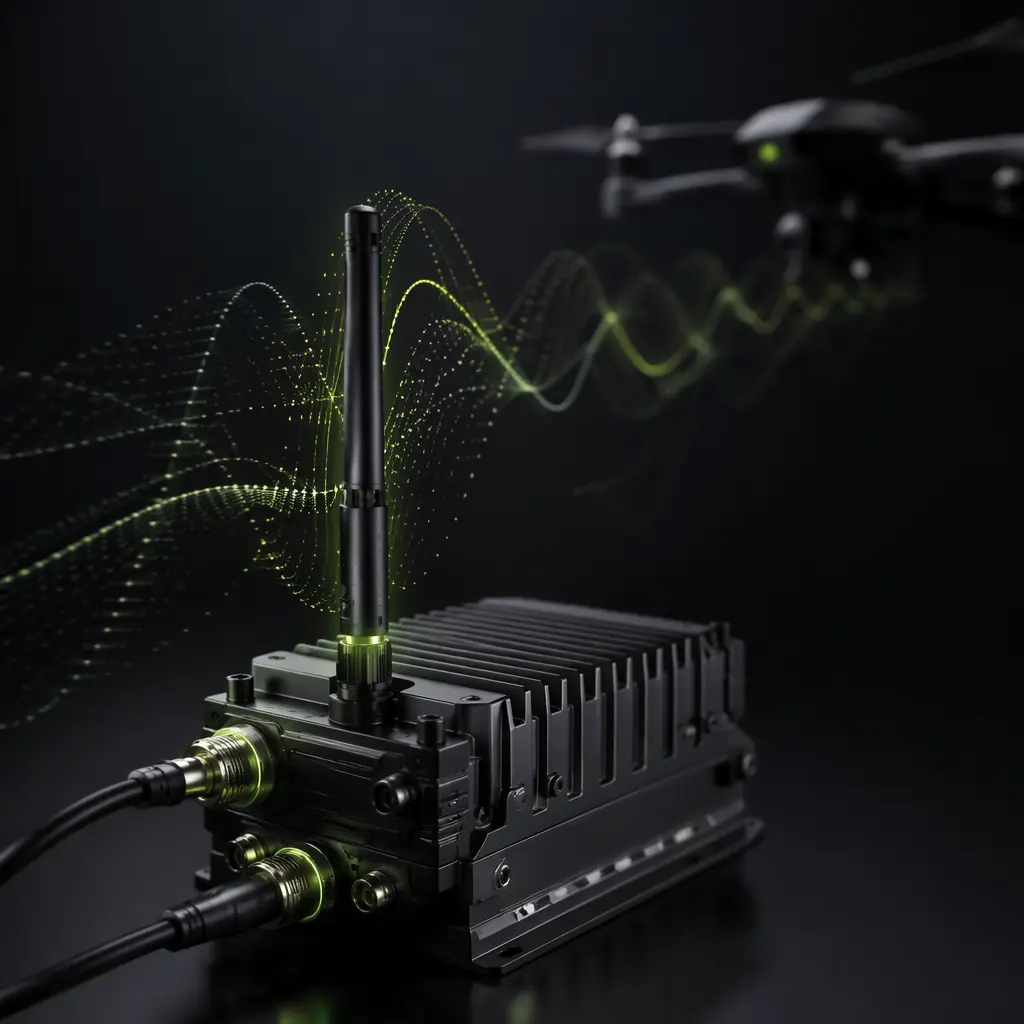
End-to-end RF architecture — telemetry, command-and-control and GNSS — the frequency planning and link budget that the video downlink must coexist with.
Payload Integration Guide
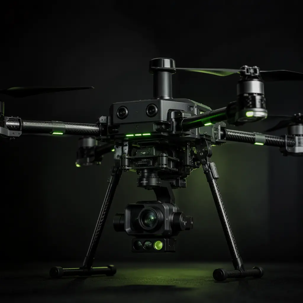
Camera, gimbal and sensor integration — the payload that generates the video signal the downlink transmits, and the interface between them.
Remote ID & BVLOS Compliance
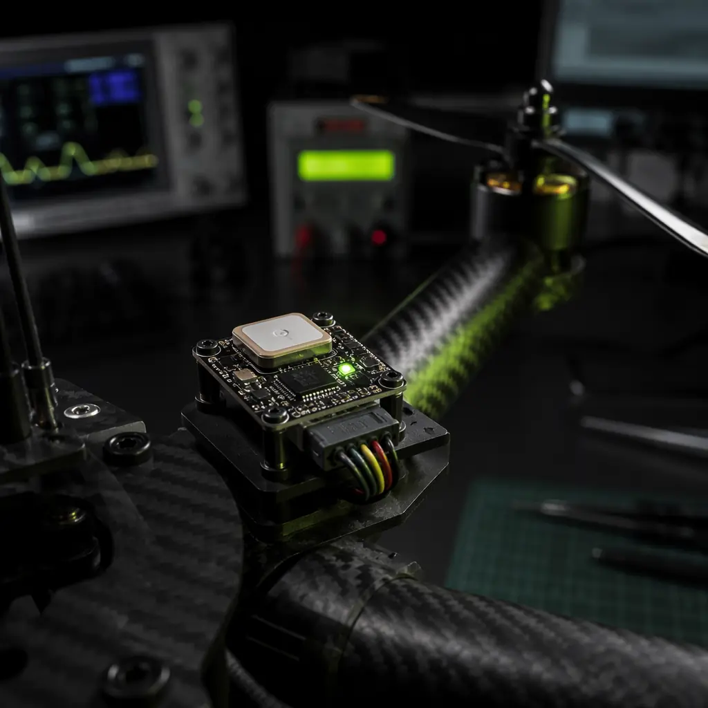
FAA and EASA BVLOS requirements — how video link loss procedures and redundant C2 links fit into the regulatory framework.
Public Safety UAV Components
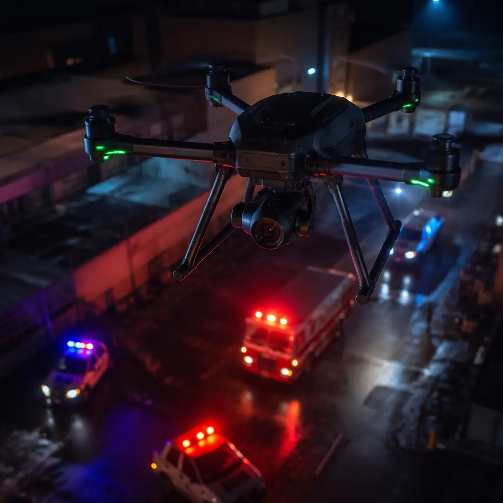
Real-time video, redundant communications and rapid deployment — the mission profile where video downlink reliability is the primary constraint.
Certification & Compliance Guide
FCC, CE and equipment authorization for RF transmitters — the regulatory approvals the video downlink must carry before it can be legally operated.