
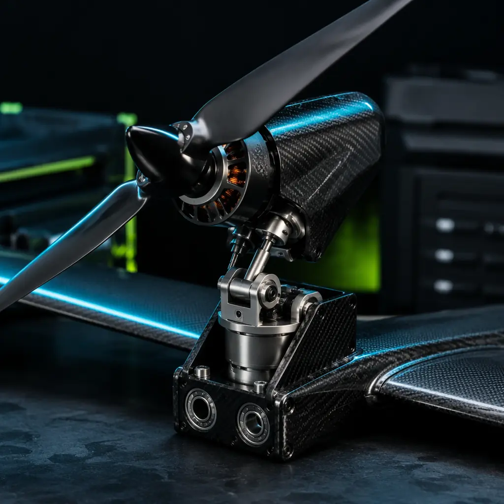
A VTOL (Vertical Take-Off and Landing) UAV combines the runway independence of a multirotor with the range and endurance of a fixed-wing aircraft — and pays for that combination with mechanical complexity, aerodynamic compromise and a flight phase that has no analogue in either multirotor or fixed-wing operations. The transition is not simply "tilting the motors forward" — it is a coordinated sequence of actuator movements, throttle changes, control surface deflections and airspeed monitoring that must execute correctly within a two-to-five-second window while the aircraft is aerodynamically unstable (the wing is not yet flying, the propellers are partially unloaded, the pitch moment from the tilted thrust vector is changing continuously, and the flight controller is running a blended control mixer that transitions from multirotor PID gains to fixed-wing PID gains in real time). The components that execute this transition — the tilt actuators, the dual propulsion system, the transition flight controller and the airframe structure that carries the loads — are not commodity items that can be selected from a generic datasheet. They must be specified as a system, with torque margins that account for aerodynamic loads at maximum transition airspeed, with redundancy that allows a single actuator failure to be survived, and with a flight controller that has been tuned for the specific aircraft geometry and tested in the full transition envelope.
For the airframe structural requirements that determine whether a VTOL UAV's motor mounts, wing spars and fuselage can survive the transition loads repeatedly — particularly the carbon fiber, aluminum and composite material selections that affect the fatigue life of the tilt mechanism's bearing housings and the wing's torsional stiffness during asymmetric thrust conditions — the UAV airframe materials guide covers the structural design decisions that interact with the VTOL transition loads. For the motor KV selection and thrust calculation that determine whether the lift motors can provide the hover thrust margin needed during the transition's initial acceleration phase — when the propellers are tilted 30–60 degrees and producing both vertical lift and horizontal thrust simultaneously — the UAV brushless motor KV selection guide covers the thrust calculation methodology. This article focuses on the transition-specific components — the tilt actuators, the dual propulsion architecture, the transition controller and the integration that makes them work together.
The four VTOL architectures — and what they demand from the component supply chain
VTOL UAVs fall into four architectural categories, each with a fundamentally different set of transition components and a different procurement risk profile. Understanding which architecture the project is committed to is the first procurement decision — because the architecture determines whether the transition-critical components are off-the-shelf or custom, whether a single actuator failure is survivable, and whether the aircraft can be converted from a multirotor test platform to a VTOL prototype with incremental hardware changes or requires a complete airframe redesign.
Tilt-rotor. The propulsion units — each consisting of a motor, an ESC and a propeller — are mounted on nacelles that rotate from vertical (hover) to horizontal (cruise) on a tilt axis located at the wing's leading edge or mid-chord. The tilt mechanism is a servo or a brushless actuator driving a shaft through a gear reduction; the shaft is supported by two bearings (one in the nacelle, one in the wing spar) and carries the full thrust load of the propulsion unit (typically 2–8 kg per nacelle for a UAV with a 10–25 kg MTOW) plus the aerodynamic drag on the nacelle at cruise speed — a combined bending moment of 15–50 N·m at the bearing, which the actuator's output shaft must withstand without yielding and without developing backlash that would allow the nacelle to flutter. The procurement-critical components are the tilt actuator (torque rating, gear material, position feedback resolution), the tilt shaft bearings (angular contact or tapered roller, sealed against FOD), the wiring harness that must flex through 90 degrees of rotation 500–2,000 times over the aircraft's service life without conductor fatigue, and the ESC-to-motor wiring that must be routed through the rotating nacelle without chafing against the tilt shaft.
 Concept illustration
Tail-sitter. The entire aircraft sits on its tail for takeoff — the fuselage is vertical, the propellers pull the aircraft upward, and at the transition altitude (typically 30–60 metres), the aircraft pitches forward 90 degrees to horizontal cruise, with the propellers now pulling the aircraft forward. There is no tilt mechanism — the transition is executed by differential throttle and elevon deflection, which means the procurement-critical components are the flight controller's transition logic (the autopilot must manage the 90-degree pitch maneuver while maintaining altitude and avoiding a stall during the pitch-over, which is a more aggressive maneuver than the tilt-rotor's gradual thrust-vector rotation), the airframe structure (the fuselage must withstand landing on its tail — a tail-strike at 0.5–1.0 m/s vertical velocity, which requires a crushable tail cone or a shock-absorbing landing pad), and the propulsion system (the motors must be sized for both hover thrust — where they carry 100% of the aircraft's weight — and cruise thrust — where they carry only the drag, typically 10–20% of the weight — which means the motors are oversized for cruise and operate at 30–50% of their maximum continuous power for 90% of the flight, a significant efficiency penalty).
Separate lift-plus-cruise. The UAV carries two independent propulsion systems: a set of lift motors (typically 4–8, configured as a multirotor) that provide vertical thrust for hover and transition, and a separate cruise motor (a tractor or pusher propeller on the nose or tail) that provides horizontal thrust for cruise. The lift motors are shut down after the transition is complete — they are dead weight for the cruise portion of the flight, contributing 10–20% of the aircraft's empty weight in motors, ESCs, propellers and mounting structure that serve no purpose during 80–90% of the flight time. The procurement-critical components are the lift motors (must be lightweight — 50–80 grams each for a 10 kg UAV, which limits the hover thrust to approximately 1.5–2.0 kg per motor and requires 6–8 lift motors for a 10 kg aircraft), the lift motor folding mechanism (if the lift propellers are folded during cruise to reduce drag — a folding propeller hub that must deploy reliably at the start of every transition back to hover, which is the single-point failure that has caused more lift-plus-cruise UAV crashes than any other component), and the power distribution system (two separate battery-to-ESC power buses — one for the lift motors, one for the cruise motor — that must be switched by the flight controller during the transition, with the lift bus disconnected after transition to prevent the lift ESCs from drawing standby current).
Tilt-wing. The entire wing — with the propulsion units fixed to it — rotates from vertical to horizontal on a central pivot, tilting the thrust vector and the wing's lift vector simultaneously. The aerodynamic advantage is that the wing generates lift throughout the transition (because the wing's angle of attack decreases gradually from 90 degrees to the cruise angle), reducing the thrust required from the propellers and improving the transition efficiency. The mechanical disadvantage is that the tilt mechanism must rotate the entire wing — including the propulsion units, the wing structure, the control surfaces and the wiring — which requires a much larger actuator than a tilt-rotor (typically 50–150 N·m of torque for a 2.5-metre wingspan UAV, compared to 15–30 N·m for a tilt-rotor nacelle), and the actuator's failure during transition leaves the wing at an intermediate angle where neither the hover nor the cruise control laws can maintain stable flight.
The procurement risk profile increases from tail-sitter (lowest — no tilt mechanism to fail, the transition is purely a flight controller function) to tilt-rotor (medium — the tilt mechanism is a single-point failure but the actuator is a well-understood component with established reliability data from the servo and robotics industries) to separate lift-plus-cruise (medium-high — the folding propeller mechanism is the least reliable component in any VTOL architecture and has the highest in-service failure rate) to tilt-wing (highest — the tilt mechanism is custom, the loads are high, and a failure is unrecoverable). For the propulsion testing and validation methodology that verifies the tilt actuator's torque margin, the folding propeller's deployment reliability and the transition controller's logic under all failure modes — the UAV propulsion testing and validation guide covers the thrust stand, the thermal endurance and the lifetime prediction methodology for VTOL propulsion components.
Tilt actuator specification: torque, backlash, duty cycle and redundancy
The tilt actuator is the component that most directly determines whether a tilt-rotor or tilt-wing VTOL UAV transitions reliably. Selecting it requires understanding four parameters that are not always clearly stated on a servo datasheet — and that, when misunderstood, lead to actuators that stall in flight, develop backlash that allows the nacelle to flutter, or overheat during repeated transitions.
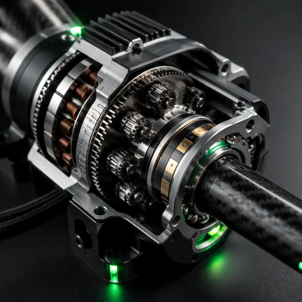
Torque margin. The actuator's stall torque must exceed the maximum aerodynamic load on the nacelle by a factor of 2.0–3.0×. The aerodynamic load is not the static thrust of the propulsion unit — it is the bending moment created by the propeller's thrust vector (which acts perpendicular to the tilt axis when the nacelle is at intermediate angles) plus the aerodynamic drag on the nacelle at the maximum transition airspeed (typically 50–80 km/h for the transition, during which the nacelle is partially tilted and presents a larger cross-section to the airflow than in cruise). For a tilt-rotor nacelle carrying a 2.2 kg thrust propulsion unit (a 500–700 W motor with a 15–16-inch propeller), the aerodynamic bending moment at 60 km/h with the nacelle at 45 degrees is approximately 8–12 N·m — which means the actuator must provide a minimum stall torque of 24–36 N·m (2.0–3.0× safety factor). A standard 40 kg·cm hobby servo provides 3.9 N·m — an order of magnitude too low. The correct actuator for this application is a brushless servo or a direct-drive torque motor in the 30–50 kg·cm class (29–49 N·m), with a metal gear train (steel or titanium gears, not brass or aluminum — brass gears wear at the tooth contact surface after 200–500 cycles under reversing loads, developing backlash that grows from 0.05 degrees to 0.5–1.0 degrees and eventually allows the nacelle to oscillate at the propeller's blade-pass frequency).
Backlash and position feedback. The actuator's position feedback — whether a potentiometer, a magnetic encoder or an optical encoder — determines how precisely the flight controller can command the nacelle angle. A potentiometer-based servo provides approximately 0.5–1.0 degrees of position accuracy (limited by the potentiometer's linearity and the ADC resolution), which is adequate for tilt-rotor transitions where the nacelle angle changes gradually. A magnetic encoder provides 0.1–0.2 degrees of accuracy and, critically, is immune to the wear and contamination that degrade a potentiometer's accuracy over time — a magnetic encoder's output does not change as the actuator's gears wear, whereas a potentiometer's output drifts as the wiper contact wears, causing the flight controller to command a nacelle angle that is 1–2 degrees different from the actual angle, which at 80 km/h translates to a thrust vector error of 3–5% of the total thrust — enough to create an uncommanded pitch or roll moment that the autopilot must correct. The procurement specification should require a magnetic encoder with at least 12-bit resolution (4,096 positions per 360 degrees, or 0.088 degrees per count) and the position feedback should be accessible to the flight controller over a digital bus (CAN, UART or PWM with telemetry — not an analog voltage that is susceptible to noise on the signal wire).
 Concept illustration
Duty cycle and thermal management. A tilt actuator operates intermittently — it moves the nacelle from vertical to horizontal over 2–5 seconds during the transition, holds the cruise position for the duration of the flight (30–120 minutes), and then moves the nacelle back to vertical over 2–5 seconds during the landing transition. This is a duty cycle of approximately 10 seconds of movement per flight — but the actuator is energized and holding torque against the aerodynamic load for the entire cruise duration, which means the motor windings are dissipating heat continuously. A standard servo's holding current is typically 5–15% of the stall current — for a 50 kg·cm servo drawing 5 A at stall, the holding current is 0.25–0.75 A, which at 7.4 V (2S LiPo) dissipates 1.85–5.55 W continuously. In still air, this heat dissipates through the servo case. In a nacelle that is mounted inside a composite fairing with limited airflow — and that is adjacent to a motor and ESC that are also dissipating heat — the servo's internal temperature can rise 20–40°C above ambient, approaching the Curie temperature of the motor's permanent magnets (80–120°C for neodymium magnets, above which the magnets begin to demagnetize irreversibly, reducing the motor's torque constant and eventually causing the servo to stall at a torque below its rated value). The procurement specification should require the actuator's continuous holding torque rating at the expected operating temperature, not just the room-temperature stall torque — and should include a thermal test: hold the actuator at 70% of its rated torque for 30 minutes and verify that the winding temperature does not exceed 80°C.
Redundancy. A single tilt actuator is a single-point failure that can cause the loss of the aircraft. The redundancy options, in order of increasing cost and complexity, are: dual actuators on the same tilt shaft (two independent servos driving the same shaft through a differential gearbox — if one jams, the other can still rotate the shaft, though at reduced speed and with increased backlash from the differential); a spring-loaded failsafe that drives the nacelle to a predetermined angle (typically 45 degrees — a partially tilted position where the aircraft can attempt a controlled descent using a blended hover-cruise control law, though this has never been demonstrated successfully in a production UAV and remains an experimental concept); and a redundant tilt axis (two independent tilt shafts per wing, each tilting a subset of the propulsion units — if one shaft jams, the aircraft can complete the transition using the remaining propulsion units, though with asymmetric thrust that the flight controller must compensate). For industrial UAVs operating over people or valuable payloads, the dual-actuator configuration is the minimum acceptable redundancy level — the cost premium is approximately $150–300 per tilt axis (the second servo, the differential gearbox and the additional wiring), which on a $15,000–50,000 industrial VTOL UAV is a 1–2% increase in the airframe cost for the elimination of a single-point failure mode. For the autopilot selection that determines the transition logic and the failure-handling behavior — including ArduPilot and PX4's VTOL support, the Q_TILT parameters and the transition airspeed management — the ArduPilot vs PX4 autopilot comparison covers the VTOL-specific features of each platform.
Dual propulsion: sizing the lift motors and the cruise motor for the transition power peak
The propulsion system of a VTOL UAV must satisfy two conflicting requirements: high static thrust for hover (where the figure of merit is grams of thrust per watt of electrical power, typically 6–10 g/W for a well-matched multirotor propulsion system) and high cruise efficiency (where the figure of merit is the lift-to-drag ratio — typically 8–15 for a fixed-wing UAV — and the propulsion system's efficiency at 50–70% of its maximum power, which is where the cruise motor operates for most of the flight). A propulsion system optimized for hover — high-KV motors with small-diameter, high-pitch propellers — is inefficient in cruise (the small propeller disc area produces high disc loading and a low propulsive efficiency at cruise speed). A propulsion system optimized for cruise — low-KV motors with large-diameter, low-pitch propellers — cannot provide the static thrust needed for hover (the low RPM limits the maximum thrust, and the large propeller diameter creates tip-clearance problems on a multirotor configuration).
The solution for tilt-rotor and tilt-wing architectures is a compromise propeller — a diameter and pitch that provide adequate hover thrust (2.0–2.5 kg of thrust per motor for a 10 kg UAV with 4 tilt-rotors, or 2.5 kg per motor with a 20% hover thrust margin) and acceptable cruise efficiency (a propulsive efficiency of 70–80% at the cruise airspeed, which for a 20 m/s cruise speed and a 6,000 RPM motor translates to a propeller pitch of approximately 6–8 inches — a 15×7 or 16×8 propeller on a 400–500 KV motor on 6S). The solution for separate lift-plus-cruise architectures is two independent propulsion optimizations — lift motors with high static thrust (6–8 motors at 400–600 KV on 6S with 13–15-inch propellers, providing 1.5–2.0 kg of thrust each) and a cruise motor with high efficiency at 50–70% power (a single 300–400 KV motor on 6S with a 16–18-inch propeller, providing 2–3 kg of cruise thrust at 50% throttle and consuming 150–250 W — an efficiency of 8–12 g/W, 2–3× better than the lift motors' hover efficiency).
 Concept illustration
The transition power peak. During the transition, the propulsion system must deliver more power than at any other point in the flight. For a tilt-rotor, when the nacelles are at 45 degrees, the vertical component of the thrust is 0.707× the total thrust (cos 45° = sin 45° = 0.707) — so to maintain hover altitude during the transition, the total thrust must increase to 1.414× the hover thrust (1 / 0.707), which means the motors must produce 41% more power during the transition than in hover. For a 10 kg UAV with 4 tilt-rotors, the hover power is approximately 800–1,200 W (200–300 W per motor), so the transition power peak is 1,130–1,700 W — and the battery, the ESCs and the wiring must be rated for this peak, not for the hover power. A 6S 10,000 mAh LiPo battery rated for 25C continuous discharge can deliver 250 A × 22.2 V = 5,550 W — more than adequate for the transition peak — but the voltage sag at 1,700 W is approximately 1.5–2.5 V (the pack's internal resistance, typically 2–5 mΩ per cell × 6 cells = 12–30 mΩ total, causes a voltage drop of 12–30 mΩ × 77 A = 0.9–2.3 V at 1,700 W), which reduces the motor RPM and the thrust by 7–11% at the moment when the aircraft can least afford a thrust reduction. The procurement specification must include a battery that maintains above 3.5 V/cell (21 V for 6S) at the transition power peak — which for a 1,700 W peak means a battery with an internal resistance below 15 mΩ total, or 2.5 mΩ per cell, which is achievable with a high-quality 25–35C LiPo pack but not with a budget 10–15C pack. For the battery selection methodology that matches the cell chemistry, the discharge rate and the capacity to the propulsion system's power profile — the UAV battery and power management guide covers the electrical power system design.
Transition flight controller: the autopilot that manages the impossible phase
The transition is the only flight phase where a VTOL UAV is neither a multirotor nor a fixed-wing aircraft — it is a hybrid vehicle with changing aerodynamics, changing control authorities and changing stability derivatives, all within a two-to-five-second window. The flight controller that manages this phase must execute a blended control mixer that transitions from multirotor control laws (altitude hold via total thrust, roll/pitch via differential thrust, yaw via differential torque) to fixed-wing control laws (altitude hold via pitch angle and throttle, roll via ailerons, yaw via rudder) — and the blending must be smooth, because a discontinuity in the control mixer at the moment the aircraft crosses the stall speed (typically 15–18 m/s for a 10 kg UAV) will cause a pitch or roll transient that the aircraft's reduced control authority (the ailerons and elevator are not yet effective at low airspeed) cannot correct.
Both ArduPilot and PX4 provide VTOL support with parameterized transition logic. The procurement-critical parameters are: the transition airspeed (the minimum airspeed at which the fixed-wing control surfaces have sufficient authority to maintain stable flight — typically 1.3× the stall speed, or 19–23 m/s for a UAV with a 15 m/s stall speed); the transition time (the duration over which the tilt angle changes from 90 degrees to 0 degrees, or the control mixer blends from multirotor to fixed-wing — typically 2–5 seconds, with longer transitions providing smoother blending but consuming more battery energy and exposing the aircraft to gust-induced attitude disturbances for longer); the minimum transition altitude (the altitude below which the flight controller will not initiate a transition — typically 30–50 metres, providing sufficient altitude to recover from a failed transition by aborting back to hover); and the transition failsafe behavior (if the airspeed does not increase as expected during the transition — indicating that the cruise motor has failed, the propeller has thrown a blade, or the aircraft has encountered a wind shear — the flight controller must abort the transition, return the tilt angle to vertical, and climb back to the hover altitude, all without exceeding the aircraft's pitch or roll limits).
The procurement specification should require that the flight controller's transition logic be tested in a hardware-in-the-loop (HITL) simulation before the first flight — feeding the flight controller simulated sensor data (IMU, GPS, airspeed, tilt angle feedback) and verifying that the transition executes correctly for the full range of airspeeds, tilt angles and wind conditions that the aircraft will encounter. The HITL test should include failure injection: simulate a tilt actuator stall at 45 degrees, a cruise motor failure at the start of the transition, a GPS loss during the transition (forcing the flight controller to rely on the IMU and the airspeed sensor alone), and a wind gust from the rear (reducing the airspeed below the transition minimum and triggering the abort logic). For the propulsion testing methodology that validates the transition power peak, the tilt actuator's torque margin and the battery's voltage sag under the transition load — the UAV propulsion testing and validation guide covers the test stand setup and the data acquisition requirements.
Procurement checklist: what to specify on the RFQ for VTOL transition components
The following checklist translates the engineering analysis into procurement specification items that a supplier can quote against. Each item should appear on the RFQ with a pass/fail acceptance criterion — a supplier either meets the specification or they do not. Vague requirements ("reliable tilt mechanism", "high-quality actuator") produce vague responses that cannot be compared across suppliers.
Tilt actuator. Stall torque ≥ 3.0× the calculated maximum aerodynamic bending moment at the transition airspeed (provide the calculation in the RFQ appendix so the supplier can verify the torque rating is sufficient). Gear material: steel or titanium, not brass or aluminum. Position feedback: magnetic encoder, ≥ 12-bit resolution, digital output (CAN, UART or PWM with telemetry). Holding torque at 80°C case temperature ≥ 1.5× the maximum aerodynamic bending moment (provide the thermal environment specification: nacelle internal temperature range, adjacent heat sources). Duty cycle: 5 seconds of movement per 30-minute flight, continuous holding at cruise torque for the flight duration. Backlash: < 0.2 degrees at the output shaft after 500 cycles of ±90-degree movement under the rated torque. Life: 2,000 cycles minimum (500 flights × 2 transitions per flight × 2 tilt axes, with a 2× safety factor) without exceeding the backlash specification.
Dual propulsion system. Lift motors: provide the thrust-at-voltage table (thrust in grams at 50%, 75% and 100% throttle for the specified battery voltage — typically 6S/22.2 V nominal, 21.0 V under load). Cruise motor: provide the efficiency-at-power table (grams of thrust per watt of electrical power at 25%, 50%, 75% and 100% throttle at the cruise airspeed). ESCs: DShot600 or CAN bus protocol, bidirectional telemetry (eRPM, current, temperature), rated for the transition power peak (1.5× the hover power) with a 30-second burst rating. Folding propellers (lift-plus-cruise only): deployment reliability ≥ 99.9% per actuation (demonstrated by a test report showing ≥ 1,000 consecutive successful deployments without a failure), deployment time < 0.5 seconds from the stowed to the deployed position. For the ESC firmware and protocol selection that determines the bidirectional telemetry capability — the ESC firmware selection guide covers the BLHeli_32, AM32 and FOC comparison.
Transition flight controller. Autopilot: ArduPilot 4.x or PX4 1.14+ with VTOL support. HITL validation: the supplier must provide a HITL test report showing successful transition execution for the specific aircraft configuration (number of tilt axes, motor count, airframe geometry) with the transition parameters documented. Failsafe behavior: the autopilot must abort the transition and return to hover if the airspeed is below the transition minimum, if the tilt angle feedback indicates an actuator stall, or if the GPS is lost during the transition — and the abort behavior must be documented in the HITL test report.
Airframe integration. Tilt shaft bearings: angular contact or tapered roller, sealed against FOD, rated for the combined radial and thrust loads at the maximum transition airspeed with a 2.0× safety factor. Wiring: the tilt-axis wiring harness must be rated for 2,000 flex cycles at ±90 degrees of rotation with < 10% increase in conductor resistance (demonstrated by a flex-test report). The airframe structure at the tilt mechanism's mounting points must withstand the maximum aerodynamic bending moment with a 3.0× safety factor (for composite structures, the safety factor accounts for manufacturing variability in the laminate thickness and the fiber orientation; for metal structures, the safety factor is 2.0×).
Explore custom engineering Back to Blog
Continue Reading
ArduPilot vs PX4 Autopilot
Which open-source autopilot handles VTOL transitions better — the Q_TILT parameters, the transition airspeed management and the failsafe behavior compared across both platforms.
Motor KV Selection Guide
Thrust calculation, stator sizing and thermal budget — how the motor's KV rating determines whether the lift motors can provide the hover thrust margin during the transition's power peak.
Propulsion Testing & Validation
Thrust stand, thermal endurance and lifetime prediction — the test methodology that validates the tilt actuator's torque margin and the transition power profile.
UAV Airframe Materials Guide
Carbon fiber, aluminum and composite material selections — how the airframe structure at the tilt mechanism's mounting points survives the repeated transition loads.
Battery & Power Management
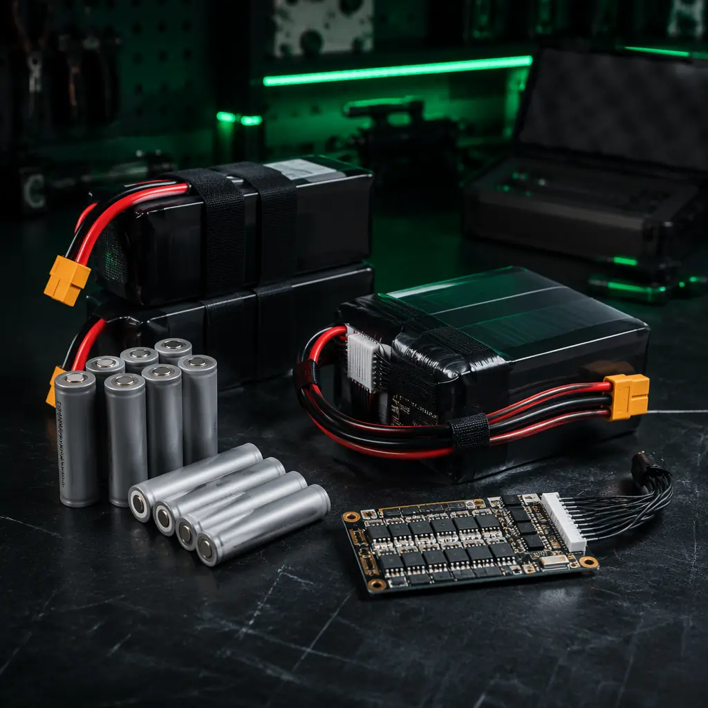
LiPo vs Li-Ion, voltage sag under load and cell configuration — how the battery's internal resistance determines whether it can deliver the transition power peak.