
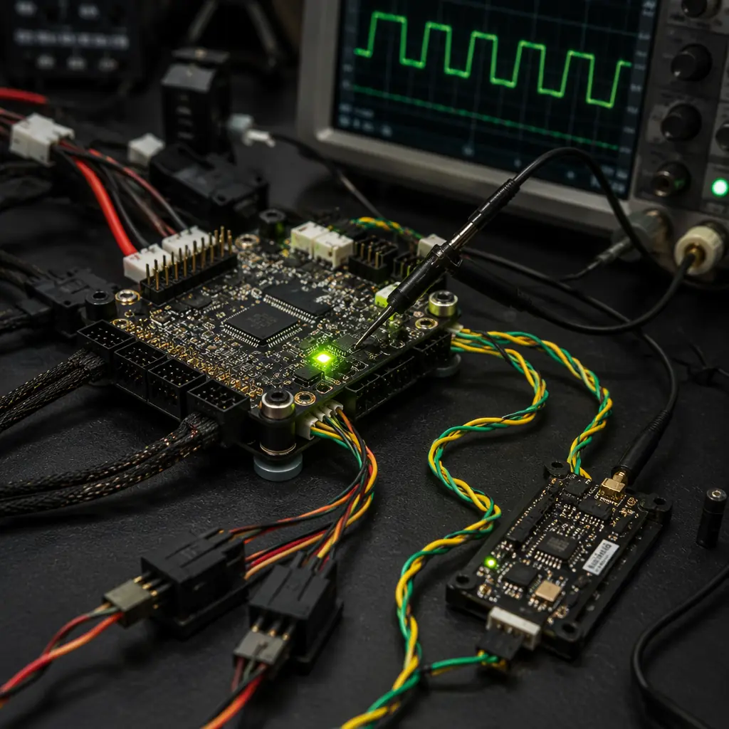
The communication protocols used in UAV avionics fall into two architectural categories — and the choice between them determines the wiring harness complexity, the fault tolerance and the upgrade path for the entire avionics stack. Point-to-point protocols — PWM, DShot and Oneshot — connect exactly two devices over dedicated wires: one flight controller output to one ESC input, one receiver output to one flight controller input. They are simple, deterministic and well-understood, but they scale linearly in wiring complexity with the motor count, they provide no built-in error detection (DShot adds a CRC, which is a significant improvement over PWM's error-detection-free analog pulse width) and they offer no bidirectional communication — the flight controller tells the ESC what to do, but the ESC cannot tell the flight controller what is happening. Bus protocols — CAN, SBUS and CRSF — connect multiple devices to a shared communication medium: CAN is a true multi-master bus that allows any node to transmit to any other node, SBUS is a unidirectional serial stream from the receiver to the flight controller (one transmitter, up to 16 channels of servo data in a single serial frame), and CRSF is a bidirectional protocol that carries both control data from the receiver to the flight controller and telemetry data from the flight controller to the radio transmitter. Bus protocols reduce wiring, provide error detection (CRC on every frame) and enable features that point-to-point protocols cannot support — automatic device discovery, firmware updates over the bus, distributed sensor fusion and graceful degradation when a node fails.
For the flight controller and ESC matching that determines the electrical interface between the FC and the ESCs — and particularly the protocol selection that determines whether the FC can read the ESC's temperature, current and RPM telemetry — the flight controller and ESC matching guide covers the FC-to-ESC interface in detail. For the ESC firmware selection that determines which protocols the ESC supports — BLHeli_32 (DShot, Oneshot, PWM), AM32 (DShot, bidirectional DShot) and FOC (CAN, UART, SPI) — the ESC firmware selection guide covers the firmware's protocol support and the implications for the avionics architecture. This article focuses on the protocols themselves — the electrical layer, the data link layer and the integration decisions that the procurement team must make when selecting components that must communicate with each other.
PWM: the 50-year-old protocol that refuses to retire
Pulse-width modulation for servo and ESC control is the simplest communication protocol in the UAV avionics stack — and the most limiting. A PWM signal is a periodic pulse whose width (the duration of the high state, typically 1,000–2,000 microseconds) encodes the commanded value: 1,000 µs = minimum throttle (motor stopped) or minimum servo angle, 1,500 µs = center, 2,000 µs = maximum throttle or maximum servo angle. The pulse repeats at a fixed frequency — 50 Hz (20 ms period) for analog servos, up to 400 Hz (2.5 ms period) for digital servos and ESCs that support high-frequency PWM input. The protocol has no addressing, no error detection, no framing — it is an analog timing signal masquerading as a digital interface, and every aspect of the information transfer is implicit: the channel identity is determined by which physical pin the signal arrives on, the value is determined by the pulse width measured by the receiver's timer capture unit, and the validity is determined by whether the pulse width falls within the expected 1,000–2,000 µs range (a pulse width outside this range — caused by electrical noise coupling into the signal line, a ground loop or a failing timer on the flight controller — is indistinguishable from a valid command to the ESC, which will either reject it as out-of-range or, worse, interpret it as a throttle command).
The procurement implications of PWM are threefold. First, every motor channel requires a dedicated signal wire from the flight controller to the ESC — an 8-motor coaxial octocopter needs 8 separate PWM signal wires (plus 8 ground reference wires, plus the power distribution wiring), which adds approximately 150–250 grams of copper to the airframe (16 × 30 cm of 22 AWG silicone wire at approximately 3.5 g/m = approximately 17 g for the signal wires alone, plus the connectors and the power distribution). Second, PWM provides no telemetry — the flight controller cannot read the ESC's temperature, current, RPM or error flags, which means the autopilot cannot detect an overheating ESC, a desyncing motor or a failing MOSFET until the UAV's flight characteristics change — by which point the component may have already been damaged. Third, PWM's timing precision is limited by the flight controller's timer resolution and the ESC's pulse measurement accuracy — at 400 Hz update rate, the timing resolution is typically 0.5–1.0 µs, which provides approximately 1,000–2,000 discrete throttle steps (adequate for hover and gentle maneuvering but marginal for aggressive control loops that demand 4,000+ steps for smooth motor control at high update rates). For a heavy-lift industrial UAV where precise thrust control is essential for stable hover with a suspended payload — and where the weight of the wiring harness directly reduces the payload capacity — PWM is a procurement decision that must be justified, not a default.
 Concept illustration
DShot: digital ESC protocol with error detection
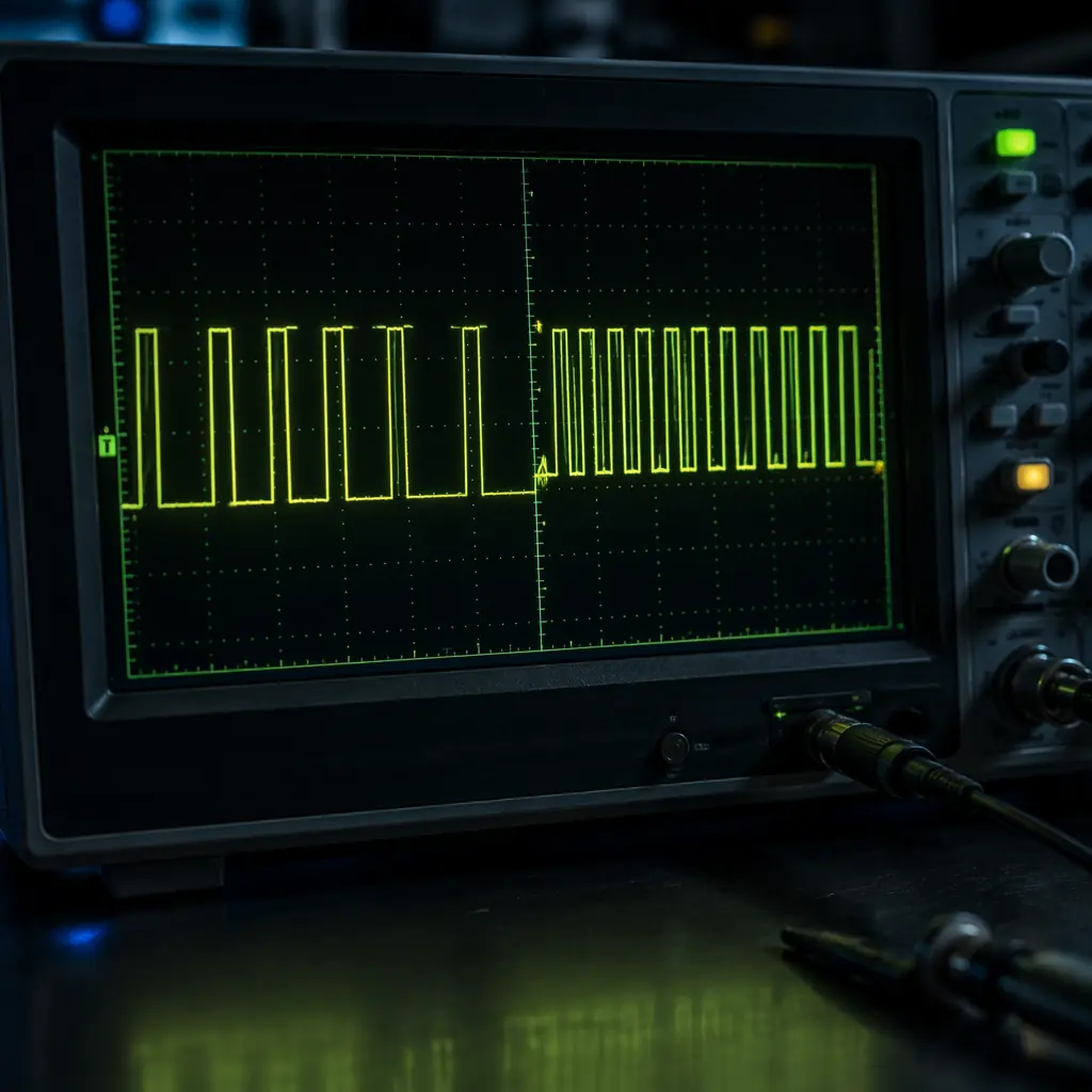
DShot is the standard digital ESC protocol for multirotor UAVs, available in four speed grades — DShot150 (150 kbps), DShot300 (300 kbps), DShot600 (600 kbps) and DShot1200 (1,200 kbps) — with each frame consisting of 16 bits: 11 bits of throttle value (0–2,047, providing 2,048 discrete steps — a 2× improvement over PWM's effective resolution), 1 bit for telemetry request, and 4 bits of CRC-4 (a cyclic redundancy check that detects any single-bit error and most multi-bit errors in the frame, providing error detection that PWM completely lacks). The frame is transmitted using a pulse-density modulation scheme — each bit is encoded as a specific ratio of high time to low time on the signal line — that is self-clocking (the receiver recovers the clock from the signal itself, eliminating the timing measurement uncertainty of PWM) and that is compatible with the same 3.3 V or 5 V logic-level interface that PWM uses, allowing a flight controller to drive a DShot ESC through the same output pin that was previously configured for PWM — no hardware change required, only a firmware configuration change.
DShot's key procurement advantage over PWM is bidirectional DShot (also called DShot Bidirectional or simply "bidirectional DShot"), an extension of the protocol that allows the ESC to send telemetry data back to the flight controller on the same signal wire — the flight controller sends a throttle command, and the ESC responds with a telemetry packet containing the motor's electrical RPM (eRPM, the commutation frequency multiplied by the motor's pole pair count, from which the mechanical RPM = eRPM / pole_pairs can be calculated), the motor current, the ESC temperature and error flags. This telemetry enables RPM-based filtering in the flight controller — the notch filter that removes the motor's vibration frequency from the gyroscope data can be tuned to the actual measured RPM rather than the commanded RPM, which improves the filter's attenuation by 10–15 dB at the motor frequency and reduces the gyroscope noise floor by approximately 30–50%, directly improving the UAV's attitude estimation accuracy and the control loop's stability margin. For industrial UAVs operating in gusty conditions where the motor RPM varies continuously as the autopilot compensates for wind gusts — and where the vibration spectrum shifts with the RPM — RPM-based filtering is not a luxury; it is the difference between a usable gyroscope signal and a noise-saturated one.
The procurement specification for DShot ESCs should require: DShot600 or DShot1200 (DShot300 is adequate for 4–6 motor multirotors with update rates up to 8 kHz, but DShot600 provides margin for 8+ motor configurations and for the bidirectional telemetry overhead, which adds approximately 20–30 µs of return-path transmission time per frame), bidirectional DShot support (the ESC must be capable of returning eRPM, current, temperature and error flags after each throttle command), and the ESC firmware must be AM32 or BLHeli_32 (both support bidirectional DShot; BLHeli_S supports unidirectional DShot only and cannot return telemetry). For the ESC firmware selection that determines the protocol support, the RPM filtering implementation and the thermal protection behavior — the ESC firmware selection guide provides the BLHeli_32, AM32 and FOC comparison with protocol-level detail.
For the end-to-end powertrain matching that connects the motor, the ESC, the battery and the propeller — and uses the DShot telemetry to validate the thrust curve, the thermal performance and the efficiency — the UAV powertrain matching guide covers the system-level integration and validation methodology that uses DShot telemetry as its primary data source.
CAN bus: the industrial-grade backbone for distributed avionics
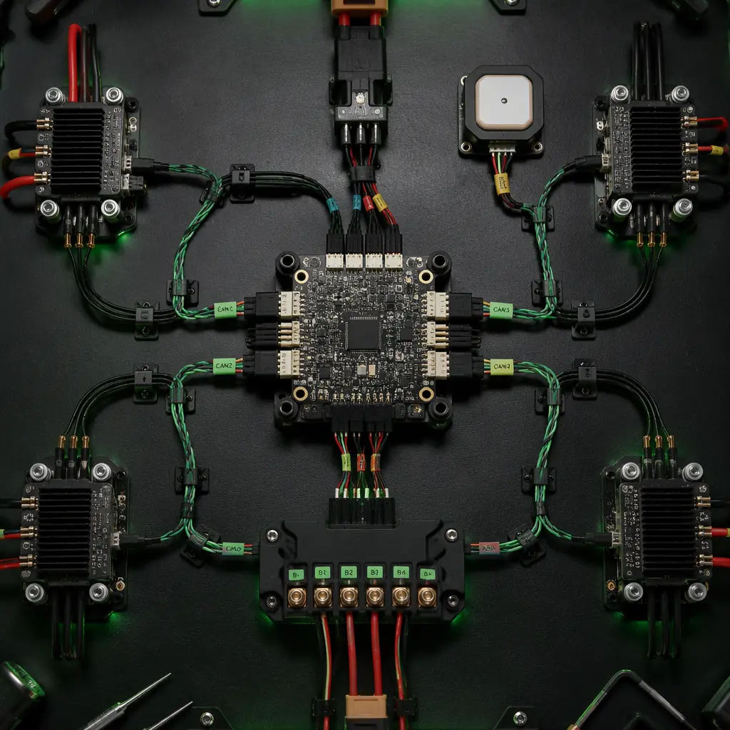
CAN (Controller Area Network) is the protocol standard for automotive and industrial control systems — and increasingly for UAV avionics as the industry moves from hobby-grade point-to-point wiring to professional-grade distributed architectures. CAN is a differential, multi-master, message-prioritized serial bus that operates at up to 1 Mbps over a twisted-pair cable with 120 Ω termination resistors at each end of the bus. The physical layer — CAN H and CAN L, a differential pair that rejects common-mode noise by design — is immune to the electromagnetic interference that corrupts single-ended PWM and DShot signals (a single-ended signal uses one wire referenced to ground; any noise that couples into the ground plane appears in the signal, and ground potential differences between the flight controller and an ESC mounted 50 cm away on the motor arm can inject tens of millivolts of noise — enough to corrupt a 3.3 V logic signal). The data link layer provides: message prioritization (lower message ID = higher priority, so a critical motor fault message with ID 0x001 will preempt a routine telemetry message with ID 0x200), error detection (15-bit CRC on every frame, plus bit stuffing error detection, frame check and acknowledgment — the probability of an undetected error is approximately 4.7 × 10⁻¹¹ per frame, or one undetected error per 1,000 years of continuous operation at 1 Mbps), automatic retransmission (if a frame is corrupted, the transmitting node automatically retries — the integrator does not need to implement a retry mechanism in application code), and fault confinement (a node that detects too many errors transitions to an error-passive state and eventually disconnects itself from the bus, preventing a single failing node from bringing down the entire bus).
The procurement case for CAN in UAV avionics is built on three architectural advantages over point-to-point protocols. First, wiring reduction: a single 4-wire CAN bus (CAN H, CAN L, V+, GND) can connect the flight controller to all ESCs, the battery management system, the payload controller and the companion computer — replacing 20–40 individual signal wires with a single harness that weighs 15–25 grams per meter (4-conductor 22 AWG twisted-pair cable) and that can be routed through a single cable gland in each motor arm, dramatically simplifying the airframe wiring and reducing the assembly time from hours to minutes. Second, distributed intelligence: CAN allows each node on the bus to process its own sensor data and report only the processed result — an ESC on CAN can monitor its own temperature, current and RPM, compare them to configurable thresholds, and report only when a threshold is exceeded or when the flight controller requests the full dataset, reducing the bus utilization from 80–90% (if every ESC were streaming raw telemetry continuously) to 5–10% (event-driven reporting with periodic health heartbeats). Third, interoperability: CAN is standardized (ISO 11898), and CANopen and UAVCAN (now DroneCAN) provide application-layer protocols that define standard message formats for motor control, battery status, GNSS position, air data and actuator commands — so a flight controller from Manufacturer A can drive an ESC from Manufacturer B over DroneCAN without custom integration, and a battery management system from Manufacturer C can report its state of charge and health to the flight controller in a format that the autopilot already understands.
The procurement specification for CAN-based UAV avionics should require: CAN FD (Flexible Data Rate) support — CAN FD extends the data field from 8 bytes to 64 bytes and increases the bitrate to up to 8 Mbps during the data phase, which is necessary for applications that transfer large data objects (firmware images, log files, high-rate sensor data) over the bus; DroneCAN protocol compliance — the ESC, the GNSS module, the air data sensor and the payload controller should use DroneCAN message formats, not proprietary CAN messages that lock the integrator into a single vendor's ecosystem; 120 Ω termination — the bus must be terminated at both ends with 120 Ω resistors (integrated into the flight controller at one end and the last ESC or a dedicated termination plug at the other end), and the procurement specification should verify that all CAN nodes on the bus include configurable termination (a jumper or a software-controlled switch) so the integrator can enable termination on the two end nodes and disable it on all intermediate nodes.
 Concept illustration
SBUS and CRSF: receiver-to-flight-controller protocols
The link between the radio receiver and the flight controller carries the most safety-critical data on the UAV — the pilot's control inputs — and the protocol that carries it determines the control latency, the channel resolution, the fail-safe behavior and the telemetry return path. Two protocols dominate the industrial UAV market: SBUS (Futaba's proprietary serial protocol, widely licensed and implemented by third-party receiver manufacturers) and CRSF (Crossfire, TBS's open protocol for the TBS Crossfire and Tracer radio links).
SBUS. SBUS is a unidirectional, inverted serial protocol running at 100 kbps with a frame rate of approximately 7–14 ms (the frame rate is determined by the radio link's update rate, not by the SBUS protocol itself — a 2.4 GHz radio link with a 7 ms frame time will produce SBUS frames at approximately 140 Hz). Each frame contains 16 proportional channels (11 bits each, 0–2,047 range) and 2 digital channels (on/off), plus a failsafe flag — if the receiver loses the radio link, the failsafe flag is set, and the flight controller can execute the pre-configured failsafe behavior (return-to-home, hold position, controlled descent or immediate landing). The SBUS signal is inverted relative to standard UART logic levels (a logic 1 is a low voltage, a logic 0 is a high voltage), which is a legacy of the original Futaba implementation and which requires an inverter circuit between the receiver and the flight controller's UART — most modern flight controllers include a dedicated SBUS input pin with a built-in inverter, but the procurement specification should verify this if the flight controller and receiver are from different manufacturers. SBUS provides no telemetry return path — the flight controller cannot send data back to the radio transmitter over the SBUS link — so the UAV's battery voltage, GPS coordinates, altitude and attitude cannot be displayed on the pilot's radio without a separate telemetry link (typically a dedicated telemetry radio on 868/915 MHz or a Bluetooth link to a ground station tablet).
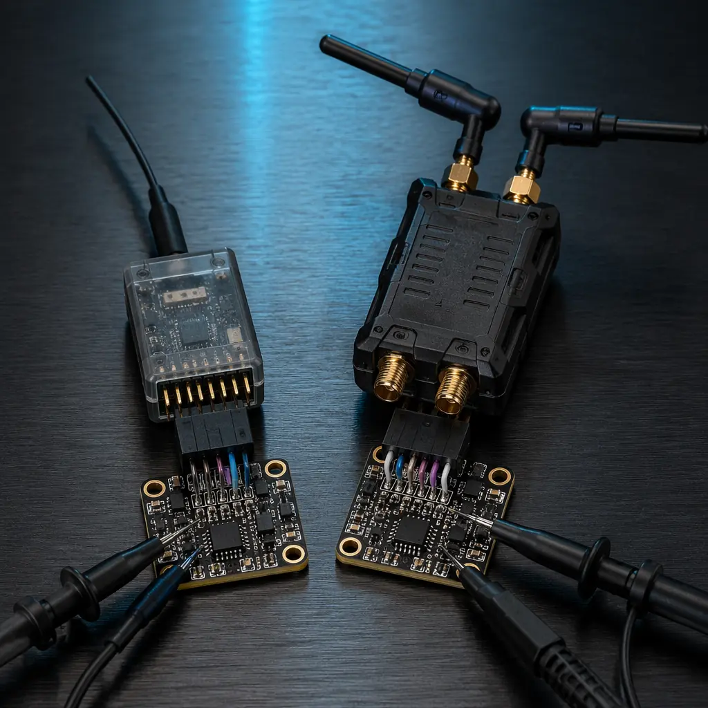
CRSF (Crossfire). CRSF is TBS's open protocol for the Crossfire and Tracer long-range radio links, operating over a standard UART at 420 kbps (Crossfire) or 250 kbps (Tracer) with a frame rate that is synchronized to the radio link's update rate — 150 Hz for Crossfire at 150 Hz mode, 250 Hz for Tracer. CRSF is bidirectional: each frame from the receiver to the flight controller contains 16 proportional channels (11 bits each, with an extended resolution mode that provides 4,095 steps for channels that benefit from higher precision — gimbal pitch, camera zoom, payload release) plus the radio link quality metrics (RSSI in dBm, link quality as a percentage, signal-to-noise ratio), and each frame from the flight controller to the receiver carries telemetry data — battery voltage, current, consumed capacity, GPS coordinates, altitude, attitude, flight mode and any custom telemetry sensors — that the radio transmitter can display on its screen, log to its SD card and forward to a ground control station over Bluetooth or Wi-Fi. The bidirectional telemetry eliminates the need for a separate telemetry radio — a single CRSF link carries both the control data and the telemetry, reducing the UAV's RF footprint (one transmitter instead of two, reducing the probability of self-interference and simplifying the frequency coordination with the video downlink and the payload data link).
The procurement comparison between SBUS and CRSF is a decision about the radio ecosystem, not just the protocol. SBUS receivers are available from dozens of manufacturers for every major radio brand — Futaba, FrSky, Jeti, Spektrum, Graupner — and the protocol is a de facto standard that any flight controller running ArduPilot or PX4 can accept without configuration. CRSF is specific to the TBS Crossfire and Tracer ecosystems — the procurement team must commit to the TBS radio link if they want CRSF's bidirectional telemetry — but Crossfire's 868/915 MHz long-range performance (10–30 km in line-of-sight conditions with the standard dipole antenna, up to 100 km with a directional antenna at the ground station) and Tracer's 2.4 GHz low-latency performance (250 Hz update rate, approximately 4 ms frame time) cover the range-latency spectrum for virtually all industrial UAV applications. For the broader RF communication system — the telemetry radio, the command-and-control link, the GNSS receiver and the video downlink — the UAV RF communication systems guide covers the end-to-end RF architecture and the frequency coordination between the control link, the telemetry link and the payload links.
 Concept illustration
Protocol selection matrix for the procurement specification
The following matrix summarizes the procurement-relevant characteristics of each protocol, organized by the avionics interface that the procurement team must specify:
FC-to-ESC interface. For multirotor UAVs with 4–8 motors, DShot600 with bidirectional telemetry is the recommended standard — it provides digital precision, error detection, RPM telemetry for notch filtering and compatibility with the entire BLHeli_32 and AM32 ESC ecosystem at a cost premium of approximately $5–10 per ESC over a PWM-only ESC. For UAVs with 8+ motors, or for heavy-lift UAVs where the wiring harness weight is a significant fraction of the payload capacity, CAN bus (DroneCAN) is the recommended upgrade — it reduces the FC-to-ESC wiring from 2N+2 wires (N signal + N ground + 2 power) to 4 wires (CAN H, CAN L, V+, GND), provides per-ESC telemetry with addressing, and enables features that DShot cannot support (ESC firmware updates over the bus, automatic motor identification and configuration, distributed thermal protection). The cost premium for CAN ESCs over DShot ESCs is approximately $15–30 per ESC, and the CAN bus transceiver and the wiring connectors add approximately $20–40 to the avionics stack's BOM — a total premium of $100–250 for an 8-motor UAV, which is justified for professional UAVs with a unit cost above $5,000 but may not be for smaller UAVs where the wiring harness weight is a small fraction of the AUW.
Receiver-to-FC interface. For UAVs operating within 2 km of the pilot with a standard 2.4 GHz radio link, SBUS is the default — it is universally supported, it is free (no licensing cost for the protocol, and SBUS receivers are commodity-priced at $15–40), and the lack of bidirectional telemetry is manageable with a separate telemetry radio (a 3DR-style 915 MHz telemetry radio adds approximately $30–50 to the BOM and provides the same telemetry data that CRSF would carry — battery voltage, GPS, attitude, flight mode — at the cost of an additional RF transmitter on the UAV). For UAVs operating beyond 2 km, or for UAVs where the radio link is the primary means of situational awareness (the pilot is flying by the telemetry display on the radio, not by visual line of sight), CRSF is recommended — the bidirectional telemetry eliminates the separate telemetry radio (saving $30–50 and 15–30 grams), the long-range 868/915 MHz Crossfire link provides control range of 10–30 km (sufficient for BVLOS operations up to the regulatory limit in most jurisdictions, typically 750 m–2 km without a waiver and 10–50 km with a BVLOS waiver), and the 150 Hz update rate provides a control latency of approximately 7–10 ms from stick movement to flight controller input (comparable to a wired SBUS connection at 7 ms frame time). For BVLOS operations where the radio link is the sole means of control, the remote ID and BVLOS compliance guide covers the redundant C2 link requirements, the lost-link procedures and the regulatory framework that governs the radio link's reliability requirements.
Payload-to-FC interface. The payload — a camera gimbal, a sensor package, a release mechanism or a spraying system — typically communicates with the flight controller over a serial UART (MAVLink protocol at 115,200 or 921,600 bps, sufficient for command-and-control of the payload and for low-bandwidth telemetry from the payload's sensors) or, for high-bandwidth payloads (a hyperspectral camera, a LiDAR scanner, a synthetic aperture radar) that generate megabytes per second of data, over Ethernet or USB 3.0 to a companion computer that processes the payload data onboard and forwards only the processed results to the flight controller over a secondary UART or CAN bus. The payload integration interface — the mechanical mounting, the electrical power, the communication protocol and the autopilot integration — is covered in the UAV payload integration guide.
Battery-to-FC interface. The battery management system (BMS) communicates with the flight controller over CAN (DroneCAN battery status message, standardized in the DroneCAN specification) or over I²C/SMBus (Smart Battery protocol, common in Li-Ion packs with integrated BMS from the laptop battery supply chain). The flight controller uses the BMS data — state of charge, cell voltages, pack temperature, discharge current — for the low-battery failsafe (trigger return-to-home when the remaining capacity drops below the energy required to return from the maximum range plus a 20% safety margin), for the remaining flight time estimation (displayed on the ground control station) and for the battery health logging (tracking the internal resistance increase over charge-discharge cycles to predict when the pack should be replaced). For the battery selection and power management methodology — including the LiPo vs Li-Ion trade-off, the cell configuration and the voltage sag characteristics that affect the flight time estimation — the UAV battery and power management guide covers the electrical power system design.
Explore custom engineering Back to Blog
Continue Reading
Flight Controller & ESC Matching
The electrical interface between the FC and the ESCs — how the protocol selection, the signal voltage levels and the connector type determine the avionics stack's reliability.

ESC Firmware Selection Guide
BLHeli_32, AM32 and FOC — which firmware supports which protocols, and how the firmware's protocol implementation affects the control loop performance.
UAV RF Communication Systems
The RF protocols — the control link, the telemetry link and the payload links — and how they coexist with the avionics communication buses.
UAV Powertrain Matching
End-to-end propulsion integration — how the DShot telemetry from the ESCs validates the thrust curve, the thermal performance and the system efficiency.
Battery & Power Management
The BMS-to-FC interface — CAN, I²C and SMBus — and how the flight controller uses battery telemetry for low-battery failsafe and flight time estimation.