
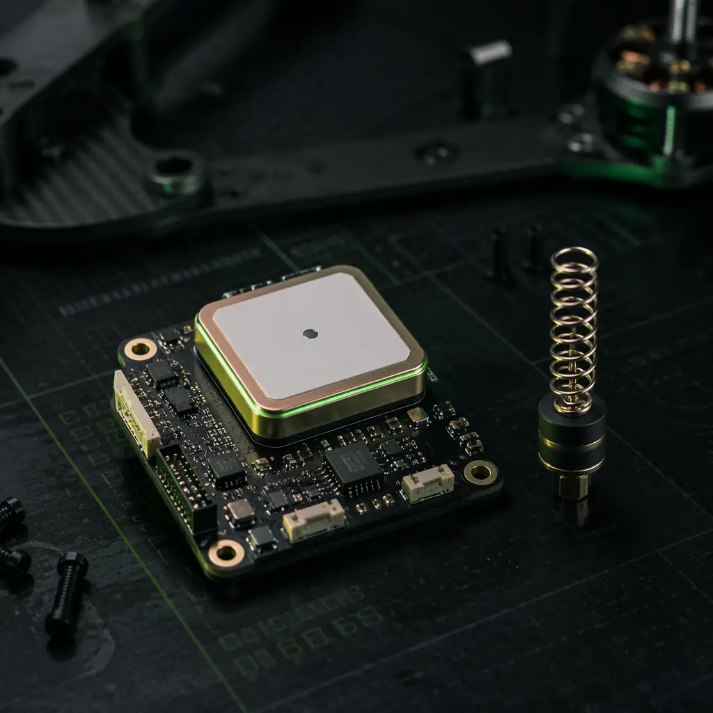
A UAV's GNSS receiver is not a GPS module — it is a navigation sensor that fuses signals from four global constellations (GPS, GLONASS, Galileo, BeiDou), two or three frequency bands (L1 at 1,575 MHz, L2 at 1,227 MHz, L5 at 1,176 MHz), a ground-based or satellite-based correction data stream (RTCM 3.x for RTK, stored raw observations for PPK), and an inertial measurement unit (the flight controller's IMU, which the GNSS module uses for velocity-aided tracking loop bandwidth reduction) — and the quality of this fusion determines whether the UAV's position estimate drifts 2.5 metres over a 30-minute flight or 2.5 centimetres. The price difference between a single-frequency L1 module ($50–150) and a multi-frequency L1/L2 module with RTK ($200–500) is $150–350 — approximately 0.5–2% of the cost of a $15,000–50,000 industrial UAV — and it buys a 100× improvement in positioning accuracy (2.5 m → 2.5 cm), a 10× improvement in time-to-first-fix after a signal loss (30–60 seconds → 3–10 seconds for RTK re-convergence), and the elimination of the ionospheric delay error that is the largest single source of GNSS positioning error (5–15 metres of zenith delay that an L1-only receiver cannot measure or correct).
For the flight controller and autopilot integration that determines how the GNSS position data flows into the navigation filter — the EKF (Extended Kalman Filter) in ArduPilot and PX4 that fuses the GNSS position with the IMU acceleration, the barometer altitude and the magnetometer heading — the ArduPilot vs PX4 autopilot comparison covers the navigation architecture that consumes the GNSS data. For the communication protocols that carry the RTK correction data from the base station to the UAV — typically over a telemetry radio link using MAVLink RTCM injection, or over 4G/LTE using NTRIP — the UAV communication protocols guide covers the CAN bus, UART and telemetry integration. This article focuses on the GNSS receiver itself: the module classes, the frequency architecture, the procurement specifications and the acceptance test criteria.
GNSS receiver classes: standalone, RTK and PPK — which accuracy tier for which mission
Industrial UAV GNSS receivers fall into three accuracy tiers, each with a fundamentally different correction methodology and a different set of procurement-critical parameters. Selecting the wrong tier — specifying an RTK module for a mission that only requires 2-metre accuracy, or specifying a standalone module for a mission that requires 3 cm GSD — is the most expensive GNSS procurement mistake, and it is made by assuming that "RTK" on the datasheet means "centimeter accuracy under all conditions" when it means "centimeter accuracy only when the correction data link is active, the baseline to the base station is under 10 km, the satellite geometry is favourable, and the receiver has maintained continuous phase lock on at least six satellites with L1 and L2 signals for the convergence period."
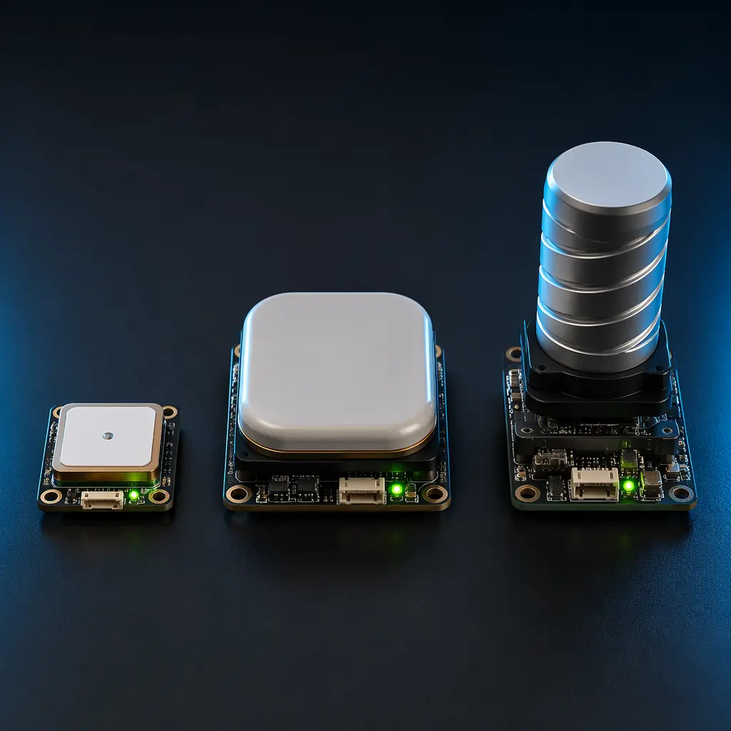
Standalone (single-frequency L1). The receiver tracks only the L1 C/A code on GPS and optionally the E1 signal on Galileo and the B1I signal on BeiDou — without any correction data, the position accuracy is 2.0–5.0 metres CEP (Circular Error Probable, meaning 50% of position fixes fall within this radius) in open-sky conditions, degrading to 5–15 metres under partial canopy or near buildings where multipath reflections introduce pseudorange errors of 10–50 metres that an L1-only receiver cannot detect because it has no second frequency to compare against. The modules in this class — u-blox NEO-M8N, M9N, M10 — cost $15–50 in single-unit quantities and are adequate for missions where the UAV's position is monitored by a human pilot watching a video feed (FPV inspection, casual aerial photography) or where the autopilot's position hold only needs to keep the aircraft within a 5–10 metre radius. They are not adequate for automated waypoint navigation where the aircraft must fly through a 2-metre-wide corridor (bridge inspection, warehouse inventory), for photogrammetry where the geotag accuracy determines the output accuracy, or for any mission requiring autonomous landing on a precise pad.
 Concept illustration
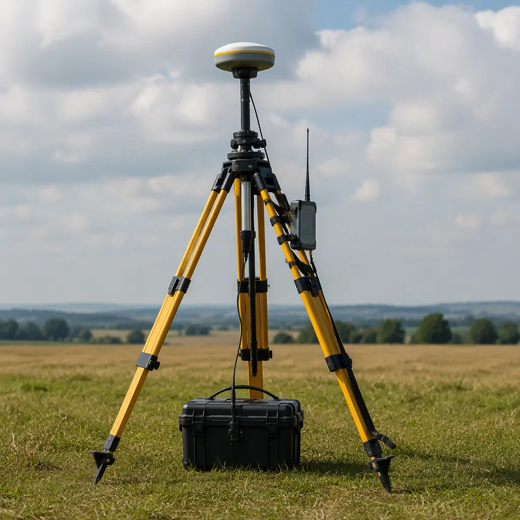
RTK (Real-Time Kinematic, L1/L2 or L1/L5). The receiver tracks the carrier phase — not just the pseudorange code — on two frequencies, and receives a real-time correction data stream from a base station (RTCM 3.x format, typically over a 900 MHz telemetry radio or a 4G NTRIP connection) that provides the base station's carrier phase observations. The rover receiver computes the integer ambiguity — the unknown number of whole carrier wavelengths between the satellite and the receiver — and once resolved (a process called ambiguity resolution or "RTK fix", which takes 5–30 seconds under good conditions with a short baseline), the position accuracy is 1–3 cm horizontally and 2–5 cm vertically. The critical parameter is the baseline length — the distance between the base station and the rover. At baselines under 5 km, the ionospheric and tropospheric delays are highly correlated between the base and the rover, and the RTK fix is robust. At baselines of 10–20 km, the atmospheric decorrelation introduces errors of 1–3 ppm of the baseline (1–3 cm per 10 km), and the ambiguity resolution becomes less reliable — the fix may take 30–120 seconds or may fail entirely if the ionosphere is active (solar maximum, equatorial regions). At baselines beyond 30 km, RTK is effectively unusable without a network RTK solution (a virtual reference station, or VRS, computed from multiple permanent base stations).
The modules in this class — u-blox ZED-F9P (L1/L2, $150–200), Septentrio mosaic-X5 (L1/L2/L5, $300–400), NovAtel OEM719 (L1/L2, $400–600) — are the standard for survey-grade UAVs, precision agriculture sprayers that need 2 cm row-following accuracy, and autonomous landing systems. The u-blox ZED-F9P is the most widely deployed RTK module in the industrial UAV market — it provides 1 cm + 1 ppm horizontal accuracy in RTK mode, tracks up to 184 channels across four constellations, and consumes 130 mW (a negligible power draw on a UAV that consumes 500–2,000 W in flight). Its primary limitation is the L1/L2-only architecture — without L5, it cannot take advantage of the L5 signal's higher chipping rate (10.23 Mcps vs 1.023 Mcps for L1 C/A), which provides better multipath rejection, or the L5 signal's pilot component (a dataless carrier that allows longer coherent integration, improving tracking sensitivity by 3–6 dB in low-signal environments).
PPK (Post-Processed Kinematic, L1/L2 or L1/L2/L5). The receiver records raw GNSS observations (pseudorange, carrier phase, Doppler, signal-to-noise ratio for every tracked satellite at 1–20 Hz) to onboard storage during the flight — no real-time correction data link is required. After the flight, the raw observations are processed against a base station's RINEX file (or a network of permanent reference stations, such as the NOAA CORS network in the United States or the EUREF network in Europe) using post-processing software (RTKLIB, NovAtel Waypoint Inertial Explorer, or the u-blox u-center PPK tool) to compute a centimeter-accurate trajectory. The PPK workflow eliminates the single largest failure mode of RTK — the correction data link (which can drop out when the UAV flies behind a building, a hill or a tree line, causing the RTK fix to degrade to a float solution with 20–50 cm accuracy until the link is restored) — because the raw observations are recorded continuously regardless of the link status. The trade-off is that PPK does not provide real-time centimeter accuracy to the flight controller — the UAV navigates on a standalone or DGPS position solution during the flight (2–5 metre accuracy), and the centimeter-accurate trajectory is only available after post-processing. This is acceptable for photogrammetry and LiDAR scanning — the geotagging or the LiDAR point cloud registration uses the post-processed trajectory, not the real-time position — but it is not acceptable for autonomous landing, precision spraying or any mission where the flight controller itself needs centimeter-level accuracy in real time.
 Concept illustration
Multi-frequency architecture: why L1/L2/L5 matters — and when it does not
The three GNSS frequency bands serve three distinct purposes in UAV positioning, and understanding which bands a mission needs is the difference between specifying a $200 module that works and a $500 module whose extra capability is never used.
L1 (1,575.42 MHz) — the baseline. Every GNSS module tracks L1. It carries the C/A (Coarse/Acquisition) code on GPS, the E1 signal on Galileo, and the B1I signal on BeiDou — and it is the only frequency tracked by standalone receivers. L1's 1.023 Mcps chipping rate produces a code chip length of approximately 293 metres — meaning a multipath reflection that travels an extra 150 metres (a signal bouncing off a building 75 metres away) adds a pseudorange error of 150 metres that the receiver cannot distinguish from the direct-path signal. In practice, multipath errors on L1 are 5–50 metres in urban environments and 1–5 metres in open-sky conditions — which is why an L1-only receiver's position solution jumps by several metres when the UAV flies near a reflective surface (a metal roof, a body of water, a glass facade).
L2 (1,227.60 MHz) — the ionospheric corrector. The ionosphere — a layer of charged particles at 50–500 km altitude — delays GNSS signals by an amount proportional to the total electron content (TEC) along the signal path and inversely proportional to the square of the frequency. The delay on L1 is approximately 1.65× the delay on L2 (because (1,575/1,227)² ≈ 1.65), and by measuring the difference in the arrival time of the same satellite's signal on L1 and L2, the receiver can compute and remove approximately 99% of the ionospheric delay — reducing the ionospheric error from 5–15 metres (uncorrected) to 5–15 cm (dual-frequency corrected). This is the single largest improvement in positioning accuracy that a dual-frequency receiver provides over a single-frequency receiver, and it is the reason that an RTK module that loses L2 tracking (because the L2 antenna gain pattern is narrower than L1's, and the aircraft's banking causes the L2 signal to drop below the tracking threshold before L1 drops) degrades to a float solution with 20–50 cm accuracy — the ionospheric error, uncorrected, overwhelms the carrier-phase measurement precision.
L5 (1,176.45 MHz) — the multipath rejector and the safety-of-life band. L5 has a 10.23 Mcps chipping rate — 10× faster than L1 C/A — which produces a code chip length of approximately 29 metres, making it inherently 10× more resistant to multipath (a reflected signal that travels an extra 30 metres produces a single-chip error on L5 vs a 0.1-chip error on L1 — and the receiver's correlator can discriminate a full-chip offset but cannot discriminate a 0.1-chip offset reliably). L5 also carries a pilot channel — a dataless carrier component that the receiver can integrate coherently for hundreds of milliseconds (compared to the 20 ms coherent integration limit on L1 C/A, which is modulated by the 50 bps navigation data message), providing 6–10 dB of additional tracking sensitivity — which is why an L1/L5 receiver can maintain a fix under tree canopy or in urban canyons where an L1/L2 receiver loses lock. The trade-off is that L5 is not yet fully deployed on all GPS satellites (as of 2026, 17 of the 31 operational GPS satellites broadcast L5, with the remaining satellites scheduled to be replaced by GPS III satellites carrying L5 by approximately 2030), so an L5-capable receiver does not always have enough L5 satellites to form an L1/L5 ionospheric correction — it falls back to L1-only when fewer than four L5 satellites are visible, which is rare at mid-latitudes (where 6–10 L5 satellites are typically visible) but common at high latitudes or in deep urban canyons where only 2–3 satellites are above the elevation mask.
For the RF communication systems that carry the RTK correction data and the telemetry link between the UAV and the ground station — including the 900 MHz and 2.4 GHz radio link budgets that determine the maximum RTK baseline — the UAV RF communication systems guide covers the frequency selection, the antenna gain and the link margin calculation.
Procurement specification: what to put on the GNSS module RFQ
A GNSS module datasheet will tell you the number of channels (184, 448, 555 — all are adequate for UAV use), the constellations tracked (GPS + GLONASS + Galileo + BeiDou is the minimum for industrial use; GPS-only is unacceptable because it limits the receiver to 31 satellites, and a UAV banking at 30 degrees will lose satellites below the antenna's gain pattern, reducing the visible count from 12–15 to 8–10 — and RTK ambiguity resolution requires a minimum of 5–6 satellites with continuous dual-frequency tracking, which a GPS-only receiver cannot guarantee during a banked turn), and the update rate (5–10 Hz is standard for UAVs; 20 Hz is available on survey-grade modules and is beneficial for fixed-wing aircraft flying at 20 m/s, where a 5 Hz update rate produces a 4-metre between-fix distance at cruise speed — the EKF interpolates between position fixes, but the interpolation error grows with the between-fix distance). The following parameters are the ones that determine whether the module will work in flight — and they are the ones that most datasheets bury in an appendix or omit entirely.
Tracking sensitivity under dynamics. A GNSS module's tracking sensitivity is specified in dBm — typically -162 to -167 dBm for acquisition (cold start, no almanac or ephemeris data) and -164 to -168 dBm for tracking (maintaining lock on an already-acquired signal). These numbers are measured with the antenna stationary — under UAV dynamics (2–4 g of acceleration during aggressive manoeuvres, 100–300 degrees per second of rotation during a banked turn), the receiver's phase-locked loop (PLL) bandwidth must be widened from the stationary setting (5–10 Hz) to a dynamic setting (15–25 Hz) to track the Doppler shift caused by the acceleration — and widening the PLL bandwidth increases the tracking noise by 3–6 dB, effectively reducing the tracking sensitivity by 3–6 dB. A module that specifies -167 dBm tracking sensitivity with an 18 Hz PLL bandwidth (the "airborne dynamic" mode on u-blox receivers) is usable for UAVs; a module that only specifies -167 dBm with a 5 Hz PLL bandwidth ("stationary" or "pedestrian" mode) will lose lock during turns and must be re-tested with the airborne dynamic mode enabled before procurement.
Time-to-first-fix (TTFF) and reacquisition time. A GNSS module's cold-start TTFF — the time from power-on to the first valid position fix when the receiver has no almanac, no ephemeris and no approximate position — is 26–35 seconds for a modern multi-constellation receiver (u-blox F9P: 25 seconds cold start typical, 2 seconds hot start with valid ephemeris). For a UAV, the cold-start TTFF is irrelevant — the receiver is powered on during the pre-flight checklist, and by the time the aircraft is armed and ready for takeoff (typically 60–120 seconds after power-on), the receiver has had ample time to acquire a fix. The parameter that matters is the reacquisition time — the time to reacquire a signal after a momentary blockage (the aircraft flies behind a building, under a bridge, or banks hard enough to occlude the antenna's view of the sky for 0.5–2.0 seconds). A receiver with a wideband front end (20–30 MHz bandwidth vs 2–5 MHz for a narrowband receiver) reacquires in 0.1–0.5 seconds because the frequency uncertainty is smaller; a narrowband receiver takes 1–3 seconds because it must search a larger frequency range. For a UAV flying at 15 m/s, a 3-second reacquisition gap means the EKF propagates the position estimate for 45 metres without a GNSS update — and the accumulated INS drift over 45 metres (assuming an IMU with 5–10 degrees per hour of gyro bias instability, typical of the ICM-20689 or BMI088 IMUs used on Pixhawk-class flight controllers) is 0.5–2.0 metres, which is acceptable for waypoint navigation but not for precision landing. The procurement specification should require a reacquisition time of ≤ 1 second at 30 dB-Hz signal strength (the typical signal strength for a satellite at 30 degrees elevation, which is the elevation mask for a UAV that banks to 30 degrees — a satellite at 30 degrees elevation that was at 45 degrees before the bank is now at the edge of the antenna's gain pattern and has a 30 dB-Hz signal strength, 10–15 dB below the 40–45 dB-Hz of a zenith satellite).
 Concept illustration
Anti-jamming and anti-spoofing. A GNSS jammer is a $50 device that broadcasts white noise across the L1 band at 0.1–1.0 W — enough to deny GNSS reception within a 100–500 metre radius, depending on the jammer's power and the receiver's distance. A GNSS spoofer is a more sophisticated device that broadcasts fake GNSS signals that mimic real satellites — the receiver acquires the fake signals, computes a false position, and the UAV flies to a location determined by the attacker. For industrial UAVs operating in civilian airspace, jamming and spoofing are not theoretical threats — GNSS jamming is routinely detected near ports (where criminals jam GPS to disable tracking devices on shipping containers), near military training areas (where GPS jamming is used for electronic warfare exercises), and near critical infrastructure (where jamming is used as part of security testing). The defense UAV components article covers GNSS-denied navigation in detail — the defense and security UAV components guide covers the MIL-STD hardware, the encrypted data links and the GNSS-denied navigation strategies, including the inertial-visual odometry that maintains position when GNSS is unavailable — but for non-defense UAVs, the minimum anti-jamming requirement is an L5-capable receiver (the L5 signal's higher power and wider bandwidth make it inherently 6–10 dB more resistant to jamming than L1) and a receiver with jamming detection (the u-blox F9P's "jamming indicator" flag, which monitors the automatic gain control (AGC) level — when the AGC saturates, indicating a strong in-band interferer, the receiver sets a flag that the flight controller can use to trigger a return-to-launch or a switch to inertial-only navigation).
Antenna selection. The GNSS module is useless without an antenna, and the antenna is the component that determines the signal-to-noise ratio, the multipath rejection and the phase centre stability — the three parameters that determine whether the RTK fix is maintained during a banked turn. A ceramic patch antenna (25×25×4 mm, the standard antenna supplied with u-blox evaluation kits) provides 3–5 dBi of gain at zenith, a 10–15 degree 3 dB beamwidth (meaning the antenna's gain drops by 3 dB when the satellite is 5–7.5 degrees from zenith — a 10–15 degree bank angle), and a phase centre that shifts by 2–5 mm as the satellite moves across the antenna's beamwidth (causing a 2–5 mm position error per satellite, which sums to a 1–3 cm RTK position error — acceptable for most applications). A helical antenna (quadrifilar helix, 25–35 mm diameter × 40–60 mm height) provides 3–5 dBi of gain with a 60–80 degree 3 dB beamwidth (maintaining gain at bank angles up to 30–40 degrees — essential for fixed-wing UAVs that bank at 25–35 degrees during survey grid turns) and a phase centre that is stable to within 1 mm across the beamwidth. The trade-off is aerodynamic drag — a 60 mm tall helical antenna on a fixed-wing UAV's fuselage adds approximately 0.5–1.0 N of drag at 20 m/s (equivalent to 5–10 W of additional cruise power, or approximately 1–2% of the cruise power) — which is acceptable for a survey UAV where the antenna performance directly determines the output accuracy but may be unacceptable for a long-endurance UAV where every watt of power is budgeted. For the payload integration that determines how the GNSS antenna and the receiver module are mechanically mounted and electrically connected to the flight controller — including the vibration isolation and the EMI shielding requirements — the UAV payload integration guide covers the electrical, mechanical and operational integration decisions.
 Concept illustration
Procurement checklist: GNSS module specification items for the RFQ
The following checklist translates the engineering analysis into procurement specification items that a supplier can quote against. Each item is accompanied by the pass/fail criterion and the test method — the supplier either demonstrates compliance or does not, and the procurement decision is based on the demonstrated performance rather than the datasheet claims.
Constellations and frequencies. GPS L1 C/A + L2C (minimum); GLONASS L1OF + L2OF (recommended for high-latitude operations, where GLONASS provides better coverage than GPS due to its 64.8-degree orbital inclination vs GPS's 55 degrees); Galileo E1 + E5b (recommended for European operations); BeiDou B1I + B2I (recommended for Asian operations). Simultaneous tracking of ≥ 3 constellations on ≥ 2 frequencies (4 constellations on 3 frequencies for L1/L2/L5 modules). Pass/fail: the supplier provides a 24-hour skyplot showing the number of satellites tracked above a 10-degree elevation mask at the intended operational latitude — the minimum satellite count (all constellations combined, dual-frequency) must be ≥ 8 at all times, and the minimum satellite count for any single constellation must be ≥ 3 (so that a constellation-level failure — GPS being jammed, GLONASS being offline — does not leave the receiver with fewer than 4 satellites, the minimum for a 3D position fix).
RTK performance. Horizontal accuracy: ≤ 1 cm + 1 ppm CEP in RTK fixed mode with baseline ≤ 10 km (the +1 ppm accounts for the baseline-dependent atmospheric decorrelation — at 10 km, the additional error is 1 cm, giving a total of 2 cm CEP). Time to RTK fix (cold start, baseline ≤ 5 km, ≥ 8 dual-frequency satellites above 15-degree elevation): ≤ 30 seconds. RTK fix availability: ≥ 95% of flight time in open-sky conditions with baseline ≤ 10 km (the fix will drop during aggressive manoeuvres, but the float solution that fills the gaps has 20–50 cm accuracy, not the 2–5 metre accuracy of standalone mode — the receiver must indicate via a status flag whether the current solution is RTK fixed, RTK float or standalone, and the flight controller must log this flag at the navigation update rate for post-flight quality analysis).
Dynamic performance. Maximum velocity: ≥ 150 m/s (540 km/h — adequate for all subsonic UAVs). Maximum acceleration: ≥ 4 g. Maximum jerk: ≥ 2 g/s. Position update rate: ≥ 5 Hz (10 Hz recommended for fixed-wing UAVs). The supplier must provide a test report showing the RTK fix availability during a simulated flight profile: a 360-degree coordinated turn at 30 degrees of bank (fixed-wing) or a 30-degree pitch-and-roll manoeuvre (multirotor) with continuous dual-frequency tracking on ≥ 6 satellites throughout the manoeuvre.
Interface and integration. UART output (3.3 V TTL, 9,600–460,800 bps, NMEA 0183 and/or u-blox UBX binary protocol — UBX is preferred because NMEA's ASCII encoding limits the position precision to 6–8 decimal places, or approximately 1–10 mm, whereas UBX's binary format provides sub-millimetre precision). RTCM 3.x input for RTK corrections (over a second UART or over the same UART with multiplexing — the receiver must accept RTCM messages on the same serial port that outputs the position data, or on a dedicated second serial port). Time pulse output (a 1 PPS signal with ≤ 30 ns RMS jitter, for synchronizing the flight controller's IMU sampling to UTC time — essential for PPK workflows where the raw observation timestamps must be aligned with the IMU data timestamps for post-processed trajectory computation).
Physical and environmental. Module dimensions: ≤ 30×30 mm (the standard u-blox form factor, compatible with Pixhawk and Cube carrier boards). Weight: ≤ 20 g (antenna excluded — the antenna adds 10–50 g depending on type). Operating temperature: -40 to +85°C (the receiver must survive the cold-soak at altitude — at 3,000 metres, the ambient temperature is approximately -15°C at ISA standard conditions, and the receiver's internal heating from the RF front end and the baseband processor raises the junction temperature by 5–15°C above ambient). Power consumption: ≤ 200 mW in full-constellation dual-frequency tracking mode (130 mW is achievable with the u-blox F9P; 300–500 mW is typical for the Septentrio mosaic-X5, which provides an L5 channel and a more powerful interference mitigation engine — the extra 200–300 mW is negligible on a UAV drawing 500–2,000 W in flight).
Certification. CE (EU), FCC (US), RoHS 3, and — for defense and dual-use applications — the module must not be subject to ITAR export controls (the u-blox F9P and the Septentrio mosaic-X5 are both designed in Switzerland and Belgium respectively and are not ITAR-controlled; the NovAtel OEM7 series is designed in Canada and is generally not ITAR-controlled but may be subject to Canadian export controls for certain destinations). For the certification and compliance requirements that govern UAV component exports — the UAV component certification and compliance guide covers the CE, FCC, RoHS, NDAA and ITAR requirements for export markets.
Acceptance test. The supplier must provide the results of a 30-minute static test — the receiver, antenna and RTK correction data link are operated in the intended configuration (base station at a known surveyed location, baseline 2–5 km) for 30 minutes, and the position output is logged at 5 Hz. The standard deviation of the horizontal position errors (computed against the surveyed antenna position) must be ≤ 1 cm, and the maximum horizontal position error over any 10-second window must be ≤ 3 cm (the 10-second window corresponds to the typical duration of a photogrammetry flight line — a 3 cm error over 10 seconds at 15 m/s covers a 150-metre flight line, and the geotagged images along that line will have a consistent 3 cm offset, which is correctable in post-processing if the offset is systematic but not correctable if the error varies within the 10-second window).
Explore custom engineering Back to Blog
Continue Reading
ArduPilot vs PX4 Autopilot
How each autopilot's EKF consumes GNSS data — the navigation filter architecture, the GPS glitch protection and the RTK integration that determines positioning reliability in flight.

UAV Components for Mapping & Surveying
RTK GNSS receivers, photogrammetry cameras and LiDAR scanners — the component selection that determines whether the survey output meets the 3 cm GSD specification.

UAV Communication Protocols
CAN bus, UART and serial protocols — how the GNSS module interfaces with the flight controller and how the RTCM correction data reaches the receiver over the telemetry link.

Defense & Security UAV Components
GNSS-denied navigation, anti-jamming hardened receivers and inertial-visual odometry — the component strategies for maintaining position when GPS is unavailable or spoofed.

UAV Certification & Compliance
CE, FCC, RoHS, NDAA and ITAR — the export control and regulatory compliance requirements that govern GNSS module procurement for different destination markets.