
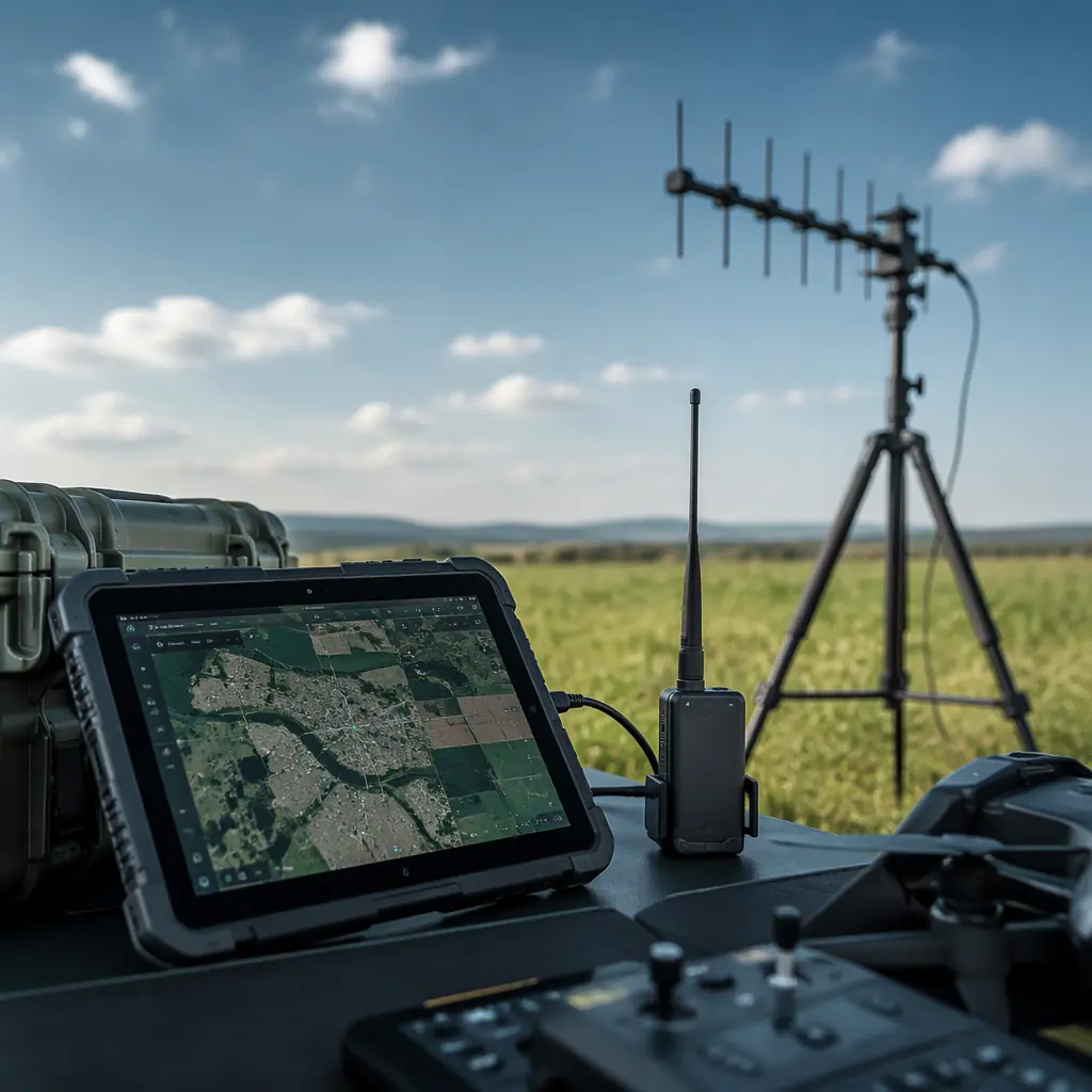
An industrial UAV mission generates approximately 50–200 kB of telemetry data per minute — GPS position at 5–10 Hz (28 bytes per MAVLink GPS_RAW_INT message × 10 Hz = 280 bytes/second), attitude at 10–50 Hz (32 bytes per ATTITUDE message × 50 Hz = 1,600 bytes/second), battery voltage and current at 1–5 Hz (24 bytes per SYS_STATUS message × 5 Hz = 120 bytes/second), plus the heartbeat (9 bytes at 1 Hz), the RC channels (42 bytes at the radio update rate), the mission waypoints (variable, typically 2–5 kB for a full mission upload) and, for BVLOS operations, the video downlink (2–10 Mbps for HD video, on a separate RF link from the telemetry). All of this data must travel from the UAV to the ground — across a distance of 2 km (a typical visual-line-of-sight inspection mission) to 50 km (a long-range BVLOS pipeline survey) — through an RF environment that is shared with Wi-Fi, cellular, ISM-band industrial equipment and other UAVs, with a link reliability requirement of >99.9% (no more than 30 seconds of telemetry dropout per 8-hour operational day). The components that make this possible — the telemetry radios, the antennas, the computing hardware and the software — are the subject of this article.
For the UAV-side RF components — the flight controller's telemetry port, the onboard telemetry radio, the antenna mounting and the frequency coordination with the control link and the video downlink — the UAV RF communication systems guide covers the airborne half of the telemetry chain. For the communication protocol that carries the telemetry data — MAVLink v1/v2, the packet structure, the message rates and the bandwidth optimization — the UAV communication protocols guide covers the data link layer. This article focuses on the ground-side hardware — the telemetry receiver, the antenna system, the computing platform and the GCS software.
Telemetry radio selection: frequency band, power, data rate and link budget
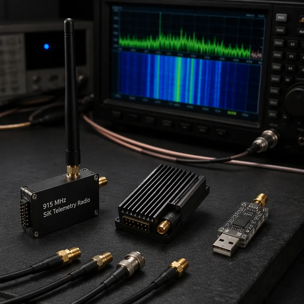
The telemetry radio is a bidirectional digital radio modem that connects the flight controller's UART (typically TELEM1 or TELEM2 on a Pixhawk-style autopilot, running at 57,600 or 115,200 bps) to the ground control station's USB port. The radio is transparent — it does not interpret the MAVLink packets, it simply relays the serial data between the UAV and the ground — which means the radio's performance is determined entirely by its RF characteristics, not by its protocol awareness. Selecting a telemetry radio requires understanding four parameters: the frequency band, the transmit power, the over-the-air data rate and the receiver sensitivity — and calculating the link budget to determine whether the combination of these parameters provides sufficient fade margin for the required range in the operating environment.
Frequency band. Industrial UAV telemetry radios operate in the ISM (Industrial, Scientific and Medical) bands: 433 MHz, 868 MHz (Europe), 915 MHz (North America, Australia) and 2.4 GHz (global). The frequency band determines the propagation characteristics and the regulatory constraints. 433 MHz penetrates foliage and light structures better than higher frequencies (the free-space path loss at 433 MHz is 6.5 dB lower than at 915 MHz for the same distance, and the diffraction around obstacles is more effective at the longer wavelength — approximately 0.69 metres at 433 MHz vs 0.33 metres at 915 MHz), but the antennas are larger (a quarter-wave monopole at 433 MHz is 17.3 cm vs 8.2 cm at 915 MHz) and the band is shared with amateur radio, ISM equipment and legacy systems, creating a higher noise floor in urban areas. 868/915 MHz is the standard for UAV telemetry — it provides a good balance of range (10–40 km with a 1 W transmitter, a 3 dBi dipole at both ends and line-of-sight), antenna size (practical quarter-wave or half-wave dipole antennas that do not interfere with the UAV's aerodynamics) and regulatory availability (the 915 MHz band in North America allows up to 1 W of transmit power under FCC Part 15.247 for frequency-hopping spread-spectrum systems). 2.4 GHz provides the highest data rates (up to 250 kbps over-the-air for 802.15.4-based radios, vs 50–100 kbps for 868/915 MHz SiK radios) but the shortest range (2–5 km with a 100 mW transmitter — the 2.4 GHz band is power-limited to 100 mW EIRP under FCC Part 15.247, which is 10 dB less than the 1 W allowed at 915 MHz, and the free-space path loss is 6.8 dB higher at 2.4 GHz than at 915 MHz) and the highest interference (the 2.4 GHz band is shared with Wi-Fi, Bluetooth, microwave ovens and consumer drones, creating a noise floor that is typically 10–20 dB higher than the 915 MHz band in populated areas).
 Concept illustration
Link budget calculation. The link budget determines whether the received signal strength at the ground station exceeds the receiver's sensitivity by a sufficient margin (the fade margin, typically 10–20 dB) to maintain a reliable link in the presence of multipath fading, antenna misalignment, atmospheric attenuation and interference. The link budget equation is: Received Power (dBm) = Transmit Power (dBm) + Transmit Antenna Gain (dBi) + Receive Antenna Gain (dBi) − Free-Space Path Loss (dB) − Cable Losses (dB) − Atmospheric Loss (dB). The free-space path loss at distance d (in metres) and frequency f (in Hz) is: FSPL = 20 log₁₀(d) + 20 log₁₀(f) − 147.55 dB. For a 915 MHz link at 10 km: FSPL = 20 log₁₀(10,000) + 20 log₁₀(915 × 10⁶) − 147.55 = 80.0 + 179.2 − 147.55 = 111.7 dB. With a 1 W (+30 dBm) transmitter, a 3 dBi dipole at the UAV, a 5 dBi dipole at the ground station and 1 dB of cable loss at each end: Received Power = +30 + 3 + 5 − 111.7 − 2 = −75.7 dBm. A SiK telemetry radio at 915 MHz has a receiver sensitivity of approximately −117 dBm at 10 kbps (the sensitivity improves — becomes more negative — at lower data rates because the receiver can integrate the signal over a longer bit period). The fade margin is −75.7 − (−117) = 41.3 dB — more than adequate for line-of-sight operation in rural environments. But at 40 km, the FSPL increases to 123.7 dB, and the received power drops to −87.7 dBm, with a fade margin of 29.3 dB — still adequate in good conditions but marginal in rain (rain attenuation at 915 MHz is approximately 0.001 dB/km, negligible for 40 km) or with foliage in the Fresnel zone (foliage attenuation is highly variable — 5–20 dB for a single tree line in the first Fresnel zone, which can reduce the margin to 9–24 dB, below the 10 dB minimum for a reliable link).
The procurement specification should require the radio supplier to provide a link budget calculation for the specific operating environment — not the "ideal conditions" range figure that appears on the datasheet. The calculation must include the terrain profile (elevation at the ground station and the expected UAV altitude along the flight path), the Fresnel zone clearance (the first Fresnel zone radius at the midpoint of a 10 km, 915 MHz link is 28.6 metres — if the terrain or obstacles protrude into the Fresnel zone, the diffraction loss is 6–20 dB), the expected interference environment (the noise floor in the operating band at the deployment location, measured with a spectrum analyzer, not estimated), and the required data rate (which determines the receiver sensitivity — at 100 kbps, a SiK radio's sensitivity degrades to approximately −110 dBm, reducing the fade margin by 7 dB).
Antenna systems: omnidirectional vs directional, tracking and diversity
The antenna is the component that converts the radio's conducted power into radiated electromagnetic energy — and that determines whether the link budget calculation's theoretical range is achieved in practice. The ground station antenna system has three degrees of freedom that the procurement specification must address: the antenna type (omnidirectional for short-range, multi-UAV operations or directional for long-range, single-UAV operations), the tracking mechanism (manual, automatic via RSSI or GPS-based), and the diversity configuration (spatial diversity with two antennas separated by at least one wavelength — 33 cm at 915 MHz — to combat multipath fading, or polarization diversity with one vertical and one horizontal antenna).
Omnidirectional antennas. A quarter-wave monopole or a half-wave dipole provides 2–3 dBi of gain with a toroidal radiation pattern — the antenna radiates equally in all azimuth directions but has a null directly above and below (along the antenna's axis). For a UAV that flies at elevation angles of 10–90 degrees above the horizon, the null directly above is a problem — when the UAV is overhead, the ground station's vertical dipole has a gain of approximately −10 dBi toward the UAV (the radiation pattern's minimum, 90 degrees off the dipole's broadside), which at 500 metres altitude reduces the received signal by 13 dB compared to a UAV at 30 degrees elevation. The solution is to tilt the antenna — a dipole mounted at 45 degrees from vertical provides a radiation pattern that covers the horizon to the zenith with a gain variation of only 3–6 dB, at the cost of 3 dB of polarization mismatch loss (the UAV's vertical antenna and the ground station's 45-degree antenna are cross-polarized, losing 3 dB of the link budget — a trade-off that is usually acceptable for the improved coverage).
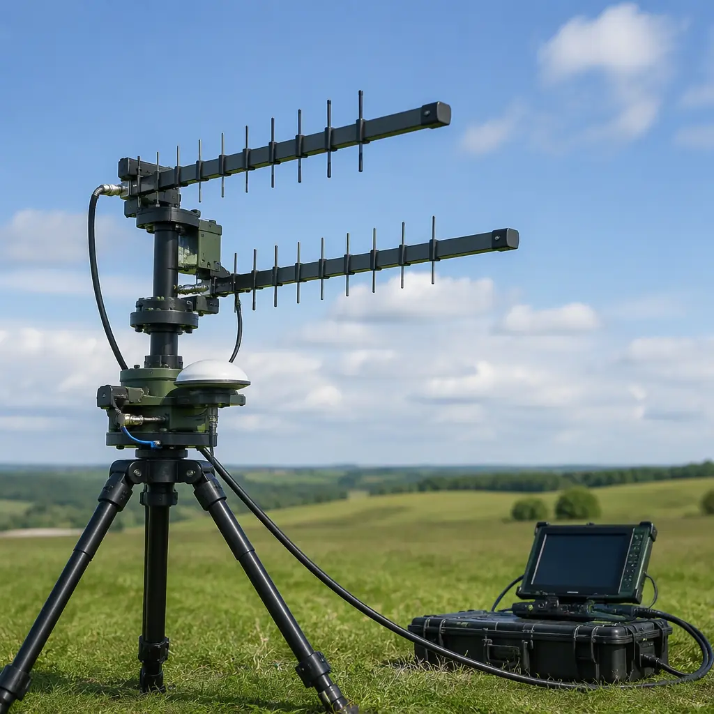
Directional antennas. A Yagi-Uda antenna (8–15 dBi gain, 30–60 degree beamwidth) or a parabolic grid antenna (15–24 dBi gain, 10–20 degree beamwidth) provides significantly higher gain than an omnidirectional antenna — but only within a narrow beam that must be pointed at the UAV. For a 915 MHz link at 40 km with a 15 dBi Yagi at the ground station and a 3 dBi dipole at the UAV: Received Power = +30 + 3 + 15 − 123.7 − 2 = −77.7 dBm, with a fade margin of 39.3 dB at 10 kbps (−117 dBm sensitivity) — 10 dB better than the omnidirectional-omnidirectional link at the same distance, providing the margin needed for reliable BVLOS operation. But the Yagi must be pointed at the UAV — and the beamwidth of a 15 dBi Yagi at 915 MHz is approximately 30 degrees (the half-power beamwidth, where the gain drops by 3 dB from the peak). If the UAV is at 40 km and the antenna is pointed 15 degrees off-axis, the gain drops to 12 dBi, and the received power drops by 3 dB — reducing the fade margin from 39.3 dB to 36.3 dB. If the antenna is 30 degrees off-axis, the gain drops to 3 dBi (the Yagi's first null), and the received power drops by 12 dB — reducing the fade margin to 27.3 dB, which may still be adequate but with reduced reliability.
 Concept illustration
Antenna tracking. An antenna tracker automatically points the directional antenna at the UAV by reading the UAV's GPS position from the telemetry stream (the ground station knows its own GPS position from a built-in GPS module, it knows the UAV's position from the MAVLink GPS_RAW_INT or GLOBAL_POSITION_INT messages, and it calculates the azimuth and elevation angles to point the antenna — typically using the Haversine formula for the azimuth and simple trigonometry for the elevation). The tracker's mechanical accuracy — how precisely it can point the antenna — must be better than half the antenna's beamwidth: for a 15 dBi Yagi with a 30-degree beamwidth, the tracker must point to within ±15 degrees to stay within the 3 dB beamwidth, which is easily achievable with hobby-grade stepper motors (0.9–1.8 degrees per step, providing ±2–4 degrees of pointing accuracy after gear reduction). For a 24 dBi parabolic grid with a 10-degree beamwidth, the tracker must point to within ±5 degrees, which requires a higher-resolution positioning system — a stepper motor with a 5:1 or 10:1 gear reduction, or a servo with position feedback, providing ±1–2 degrees of accuracy. The tracker's update rate — how frequently it recalculates the antenna position — must be faster than the UAV's angular velocity relative to the ground station: for a UAV flying at 20 m/s at a distance of 5 km, the angular velocity is arctan(20/5,000) ≈ 0.23 degrees/second, so an update rate of 5–10 Hz (the MAVLink GPS message rate) is more than adequate. At 500 metres, the angular velocity is arctan(20/500) ≈ 2.3 degrees/second — still within the tracker's capability at 10 Hz.
Diversity reception. Multipath fading — where the direct signal and a reflected signal (from the ground, a building or a body of water) arrive at the receiver with a phase difference that causes destructive interference — can create deep fades of 20–30 dB at specific antenna positions, lasting for the duration that the UAV is at the specific geometry that creates the fade (typically 0.5–2 seconds for a UAV moving at 15–20 m/s). Spatial diversity — two antennas separated by at least one wavelength (33 cm at 915 MHz) — ensures that when one antenna is in a fade, the other is unlikely to be (the probability of both antennas being in a fade simultaneously is the square of the single-antenna fade probability — if the single-antenna fade probability is 1%, the dual-antenna fade probability is 0.01%). The procurement specification should require the telemetry radio to support antenna diversity with automatic switching — the radio monitors the RSSI (Received Signal Strength Indicator) on both antennas and selects the one with the stronger signal on a packet-by-packet basis, with a switching time of < 1 ms (faster than the MAVLink packet interval of 10–20 ms). For BVLOS missions where the telemetry link is the sole source of situational awareness — and a 2-second dropout could cause the pilot to lose attitude and position information at a critical moment — the remote ID and BVLOS compliance guide covers the redundant C2 link requirements.
GCS computing hardware: rugged tablets, laptops and all-in-one controllers
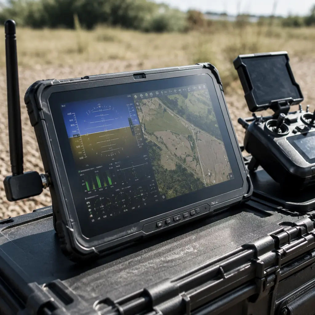
The computing platform that runs the GCS software must survive the operating environment — which for industrial UAV operations means direct sunlight (screen brightness of 800–1,500 nits to remain readable, vs 300–400 nits for a consumer laptop screen), rain and dust (IP65 or better — protected against low-pressure water jets and dust-tight), temperature extremes (−20°C to +50°C operating range for Arctic pipeline inspection and desert solar farm survey), and physical shock (MIL-STD-810G or equivalent for drop resistance — the tablet must survive a 1.2-metre drop onto concrete, which is the height of a tripod-mounted ground station).
The procurement options, in order of increasing cost and capability, are: a consumer tablet with a sunlight-readable screen protector and a weatherproof case ($300–600 — adequate for fair-weather, short-range operations where the tablet can be replaced immediately if it fails); a rugged Android tablet (Samsung Galaxy Tab Active, Panasonic Toughpad — $800–1,500 — IP68, MIL-STD-810G, 500–800 nits brightness, hot-swappable battery, suitable for most industrial UAV operations); a rugged Windows laptop (Panasonic Toughbook, Dell Latitude Rugged — $2,000–4,000 — full Windows compatibility for Mission Planner and UgCS, 1,000–1,500 nits brightness, dual hot-swappable batteries, sufficient for 8-hour operational days); and an all-in-one GCS controller (a custom console with integrated radio, antenna tracker controller, joystick, video downlink receiver and a built-in screen — $5,000–15,000 — used for military and high-end industrial BVLOS operations where a single integrated unit reduces the setup time and eliminates the cable connections between separate components that are the most common failure point in field-deployed GCS systems).
 Concept illustration
The procurement specification for the GCS computing hardware should include: operating system (Android for QGroundControl and Tower — the two most common Android GCS apps — or Windows for Mission Planner, which does not have an Android version and requires Windows for full functionality); screen brightness (≥800 nits for outdoor use in direct sunlight — this is the single most important specification for operational usability, because a screen that cannot be read in sunlight renders the entire GCS useless regardless of the telemetry link quality); battery life (≥6 hours of continuous operation at full screen brightness — enough for two 2.5-hour mapping missions plus setup and debrief, with a hot-swappable battery preferred over a single internal battery that requires the GCS to be powered down for a battery change); connectivity (USB-A for the telemetry radio, USB-C for charging and accessory expansion, Bluetooth for a secondary telemetry link or a joystick, and Wi-Fi for mission planning and data download — but the Wi-Fi radio must be disabled during flight because 2.4 GHz Wi-Fi interferes with 2.4 GHz UAV control and telemetry links); and environmental rating (IP65 minimum — protected against dust ingress and low-pressure water jets from any direction — with the operational temperature range matching the deployment environment).
GCS software: Mission Planner, QGroundControl, UgCS and the procurement decision
The GCS software is the application that displays the telemetry data, provides the mission planning interface, logs the flight data and allows the pilot to send commands to the UAV — changing the flight mode, uploading a new mission, adjusting a parameter or triggering a payload action. The software's feature set, platform support and compatibility with the autopilot determine which computing hardware can be used and which operational workflows are supported.
Mission Planner (Windows, open source). Mission Planner is the original ArduPilot ground control station — it supports the full ArduPilot parameter set (over 1,000 parameters for Copter, Plane, Rover and Sub), provides a flight data screen with a customizable instrument panel (artificial horizon, airspeed, altitude, GPS, battery, vibration), a mission planning screen with waypoint editing on satellite imagery (Bing or Google Maps), a configuration screen for initial setup and calibration, and a dataflash log analysis tool. Mission Planner runs only on Windows (it is a .NET application that uses DirectX for the map rendering and the instrument panel), which constrains the computing hardware to Windows laptops or tablets — a significant limitation for field operations where a lightweight Android tablet is preferred. Mission Planner's strength is its depth — it exposes every ArduPilot parameter, every log message and every calibration procedure, making it the tool of choice for integration engineers who need to tune the autopilot's PID gains, set up the VTOL transition parameters or analyze a post-flight vibration log. Its weakness is its user interface — it is complex, it requires training to use effectively, and it is not designed for the pilot who needs to monitor the aircraft and make quick decisions during flight (the screen is dense with data, and the critical flight information — battery voltage, GPS fix type, link quality — is not always immediately visible on the default screen layout).
QGroundControl (Windows, macOS, Linux, Android, iOS, open source). QGroundControl (QGC) is the PX4 ground control station, with ArduPilot support added in recent versions. QGC's cross-platform support (it runs on Android and iOS tablets, which Mission Planner does not) makes it the preferred GCS for field operations where a lightweight Android tablet is the computing platform of choice. QGC provides a cleaner, more pilot-oriented user interface than Mission Planner — the flight view is less cluttered, the critical flight data (battery, GPS, attitude, link quality) is displayed prominently, and the pre-flight checklist system guides the pilot through the startup sequence (sensors, GPS, radio, failsafes, control surfaces). QGC's mission planning interface is less feature-rich than Mission Planner's — it supports waypoint and survey missions but lacks some of Mission Planner's advanced mission commands (DO_JUMP, DO_REPEAT_SERVO, conditional waypoints) and its terrain-following implementation is less mature. For ArduPilot users, QGC provides approximately 80–90% of Mission Planner's functionality, with better cross-platform support and a cleaner user interface — but the remaining 10–20% (the advanced parameters, the log analysis tools and the calibration procedures) requires Mission Planner on Windows.
UgCS (Windows, commercial). UgCS (Universal Ground Control Station) by SPH Engineering is a commercial GCS designed for professional survey and inspection operations. UgCS provides automatic terrain following using SRTM or custom DSM (Digital Surface Model) data — the mission altitude is adjusted at each waypoint to maintain a constant height above the terrain, which is essential for photogrammetry missions over hilly terrain (where a constant-altitude mission would produce varying GSD — Ground Sampling Distance — across the survey area, degrading the orthomosaic quality). UgCS also provides multi-UAV mission planning (coordinating multiple UAVs to survey adjacent or overlapping areas without mid-air collisions), photogrammetry-specific mission patterns (the cross-hatch double-grid pattern that improves the orthomosaic accuracy by providing both nadir and oblique imagery of each point), and a photogrammetry calculator that estimates the GSD, the flight time and the image count based on the camera parameters and the survey area. UgCS is a Windows application that costs $500–2,000 per license (depending on the feature tier), which for a professional UAV service provider operating $20,000–100,000 UAVs is a negligible cost relative to the value of the operational efficiency it provides.
Procurement recommendation. For ArduPilot-based UAVs used in development and integration — where the engineer needs access to every parameter and every log file — Mission Planner on a rugged Windows laptop is the recommended combination. For PX4-based UAVs, or for field operations where a lightweight tablet is preferred, QGroundControl on a rugged Android tablet is the recommended combination. For professional survey and inspection operations — where terrain following, multi-UAV coordination and automated mission planning are required — UgCS on a rugged Windows laptop is the recommended combination, with QGroundControl on an Android tablet as a backup GCS that can take over if the primary GCS fails. For the broader payload integration that the GCS controls — the camera trigger, the gimbal angle, the sensor data download and the payload-specific mission planning — the UAV payload integration guide covers the payload-to-GCS interface.
Integration: the GCS as a system, not a collection of components
The ground control station's reliability is determined not by the reliability of its individual components — the radio, the antenna, the tablet and the software — but by the reliability of the connections between them. A GCS with a 99.9% reliable radio, a 99.9% reliable antenna, a 99.9% reliable tablet and 99.9% reliable software — each with a 0.1% probability of failure per flight — has a combined probability of at least one component failing of approximately 0.4% per flight (1 − 0.999⁴ = 0.004), or one failure every 250 flights. In practice, the dominant failure modes are not the components themselves but the connections: the USB cable between the telemetry radio and the tablet (the most common failure point — USB connectors are not designed for repeated plug-unplug cycles in dusty, vibrating field environments, and a loose USB connection causes the telemetry data to stop flowing without any indication that the radio link itself is still functional), the RF coaxial cable between the antenna and the radio (a loose SMA connector causes a 10–30 dB loss that reduces the link margin to zero without any visible damage to the cable), and the power supply (a depleted tablet battery or a loose power cable to the antenna tracker causes a partial or complete GCS failure that is indistinguishable from a telemetry link failure to the pilot watching the screen).
The procurement specification for the integrated GCS should include: an integration test procedure that verifies the end-to-end telemetry link — from the flight controller's TELEM port to the GCS software's flight data screen — under the expected operational conditions (range, antenna orientation, interference environment); a cable management plan (USB cables with locking connectors or right-angle connectors that reduce the strain on the tablet's USB port, RF cables with strain relief at both ends and SMA connectors that are torqued to the manufacturer's specification — typically 0.8–1.1 N·m for an SMA connector, which requires a torque wrench and cannot be achieved by hand-tightening alone); a power budget (the total power consumption of the GCS — radio, tablet, antenna tracker — and the battery capacity required for the operational duration, with a 20% margin for battery aging); and a pre-flight checklist that includes verifying the telemetry link's RSSI at the expected mission range (a ground test with the UAV at the maximum mission distance — or a link budget calculation validated by a shorter-range test — before every flight). For the communication protocol that carries the telemetry data between the UAV and the GCS — and the RF frequency coordination between the telemetry link, the control link and the payload data links — the FPV and video downlink guide covers the multi-link RF architecture for industrial UAV missions.
Procurement checklist: what to specify on the RFQ for ground control station hardware
The following checklist translates the engineering analysis into procurement specification items that a supplier can quote against.
Telemetry radio. Frequency band: 868 MHz (Europe) or 915 MHz (North America), frequency-hopping spread spectrum (FHSS) with ≥50 hopping channels. Transmit power: 1 W (+30 dBm) maximum, adjustable in software from 100 mW to 1 W. Over-the-air data rate: 10–100 kbps, with automatic rate adaptation based on the received signal strength. Receiver sensitivity: −117 dBm at 10 kbps, −110 dBm at 100 kbps. Antenna connector: SMA female on the radio, SMA male on the antenna (or RP-SMA for consumer compatibility — verify the connector gender before ordering antennas). Diversity: two antenna ports with automatic RSSI-based antenna switching, switching time < 1 ms. Interface: USB-C or USB Micro-B on the ground-side radio (for connection to the tablet or laptop), JST-GH or similar locking connector on the UAV-side radio (for connection to the flight controller's TELEM port — a locking connector is essential because a loose JST connection on a vibrating UAV causes intermittent telemetry dropouts).
Antenna system. UAV antenna: a 3 dBi half-wave dipole or a 2 dBi quarter-wave monopole, tuned to the operating frequency, with an SMA connector (verify the connector gender — the UAV radio typically uses an SMA female or an RP-SMA female, and the antenna must match). The antenna must be mounted with the active element vertical (for a dipole) and clear of the UAV's carbon fiber structure (carbon fiber is conductive and will detune the antenna if placed within one wavelength — 33 cm at 915 MHz — of the active element). Ground station antenna (short-range, <5 km): a 3–5 dBi omnidirectional dipole, mounted on a tripod at least 1.5 metres above the ground to provide Fresnel zone clearance (the first Fresnel zone radius at 5 km and 915 MHz is 20.2 metres at the midpoint, which at the ground station end is negligible because the UAV is at altitude, but the ground-level reflection from the tripod base is minimized by raising the antenna above the ground). Ground station antenna (long-range, >5 km): a 12–15 dBi Yagi-Uda or a 15–24 dBi parabolic grid, mounted on an antenna tracker with GPS-based automatic pointing, pointing accuracy ±5 degrees, update rate ≥5 Hz.
Computing hardware. Rugged tablet or laptop, IP65 minimum, MIL-STD-810G for shock and vibration, screen brightness ≥800 nits (1,000+ nits preferred), battery life ≥6 hours at full brightness with GPS, radio and screen active, USB-A port for the telemetry radio, hot-swappable battery (preferred). Verify GCS software compatibility — Mission Planner requires Windows, QGroundControl supports Windows, macOS, Linux, Android and iOS, UgCS requires Windows.
GCS software. ArduPilot integration: Mission Planner for parameter tuning and log analysis, QGroundControl for field operations. PX4 integration: QGroundControl. Professional survey and inspection: UgCS for terrain following and multi-UAV coordination. The software must be pre-configured with the correct telemetry port settings (baud rate, flow control) and the correct map provider (Bing, Google or offline maps — verify that the map tiles are cached for the operating area before the first flight, or use offline maps if the operating area has no cellular coverage).
Explore custom engineering Back to Blog
Continue Reading
UAV RF Communication Systems
The airborne half of the telemetry chain — the onboard telemetry radio, the flight controller's TELEM port, the antenna mounting and the frequency coordination with the control link and the payload links.
FPV & Video Downlink Systems
Digital vs analog, latency, range and procurement — how the video downlink coexists with the telemetry link in the UAV's RF spectrum.
UAV Communication Protocols
CAN, DShot, PWM, SBUS and CRSF — the data link layer that the telemetry radio carries between the flight controller and the ground station.
Remote ID & BVLOS Compliance
FAA and EASA regulatory requirements for BVLOS operations — the redundant C2 link, the lost-link procedures and the reliability standards that the GCS must meet.
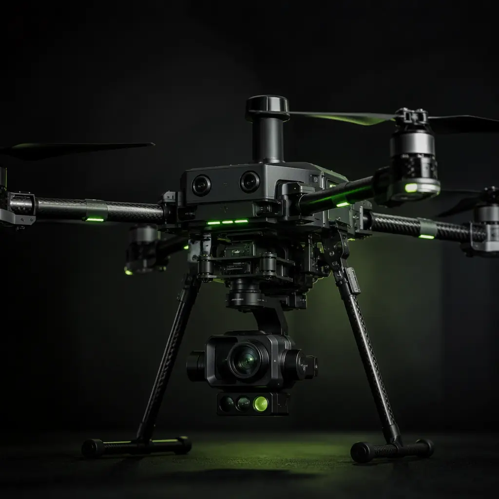
UAV Payload Integration Guide
Sensors, gimbals and release mechanisms — how the GCS controls the payload, triggers the camera and downloads the sensor data during the mission.