
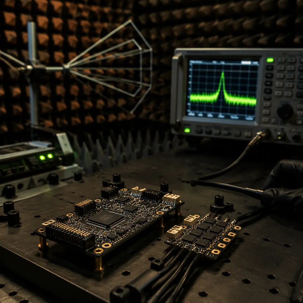
The term "electromagnetic compatibility" covers two distinct engineering disciplines that procurement teams often conflate. Emissions — the electromagnetic energy that a device radiates or conducts into its environment — is regulated by standards that limit how much noise a product can emit across a specified frequency range. Immunity — the device's ability to continue operating correctly in the presence of electromagnetic energy from other sources — is regulated by standards that define the minimum noise level a product must withstand without malfunction. A flight controller that passes radiated emissions but fails radiated immunity will operate perfectly on the bench and then reboot when the video transmitter powers on 10 cm away. An ESC that passes conducted immunity but fails conducted emissions will survive the electrical noise on the battery bus and then radiate enough broadband noise to desensitize the GPS receiver — a failure that does not show up in any individual component's acceptance test but manifests as a 30-second time-to-first-fix when the UAV is powered on at the flight line. The procurement team's EMC specification must address both sides of the compatibility equation for every component in the avionics stack, and it must recognize that passing the component-level tests does not guarantee passing the system-level tests — the interactions between compliant components create new emission sources and new immunity vulnerabilities that only system-level testing can reveal.
This article structures the EMC procurement problem into five sections that correspond to the stages of a UAV development programme. Section 1 covers the emissions and immunity standards that apply to UAV subassemblies: CISPR 22/32 and FCC Part 15 for commercial products, EN 55032 and EN 55035 for the European market, and MIL-STD-461 for defence applications — including the test methods, the frequency ranges and the pass/fail limits that the procurement team must transcribe into the component specification. Section 2 covers PCB-level EMC design rules that the procurement team should require in the supplier's design documentation: ground plane integrity, decoupling capacitor placement, trace impedance control and stack-up specification — the four design decisions that determine whether a PCB will pass EMC testing on the first submission or the fifth. Section 3 covers system-level integration: the cable routing, shielding, filtering and grounding practices that prevent the avionics bay from becoming a resonant cavity at the ESC's switching frequency. Section 4 covers pre-compliance testing: the equipment, the measurement setup and the interpretation methodology that allow the procurement team to verify EMC performance during development, before committing to the $10,000–$25,000 accredited test house. Section 5 provides the procurement specification language — the exact text that should appear in the RFQ and the supplier quality agreement to ensure that the EMC requirements are contractually binding and verifiable at incoming inspection. For the wiring-specific EMI mitigation practices — shielding, twisting, physical separation and connector grounding — the UAV connectors, wiring and power distribution guide covers the harness-level EMI management that complements the PCB-level and system-level EMC design covered in this article. For the certification documentation that the supplier must provide alongside the EMC test report — the CE Declaration of Conformity, the FCC Grant of Equipment Authorization and the test laboratory accreditation certificate — the UAV certification and compliance guide covers the full regulatory documentation package for each target market.
Emissions and immunity standards: the regulatory landscape for UAV electronics
The EMC standards that apply to a UAV subassembly depend on three factors: the product's classification (intentional radiator or unintentional radiator), the target market (United States, European Union, or defence), and the installation environment (residential, commercial, industrial or military). A GPS receiver is an unintentional radiator — it does not intentionally transmit RF energy, but its digital circuitry (the microcontroller, the UART interface, the switching regulator) generates broadband noise that must stay below the applicable emissions limits. A telemetry radio is an intentional radiator — it intentionally transmits RF energy on the 433 MHz, 868/915 MHz or 2.4 GHz ISM band, and it must meet the more stringent emissions limits for intentional radiators, which include both the in-band transmission limits (the radio must stay within its allocated frequency band and must not exceed the radiated power limit for that band) and the out-of-band spurious emissions limits (the radio's harmonics and parasitic oscillations must be suppressed by 40–60 dB below the fundamental). An ESC is a special case — it is not an intentional radiator, but the 24–48 kHz PWM switching waveform has Fourier components that extend into the hundreds of megahertz (the 200 ns MOSFET switching edge has a −3 dB bandwidth of approximately 1 / (π × 200 ns) = 1.6 MHz, and the 10th harmonic at 16 MHz, the 100th at 160 MHz and the 500th at 800 MHz all carry measurable energy), so the ESC's emissions profile is closer to that of an intentional radiator than that of a typical digital circuit.
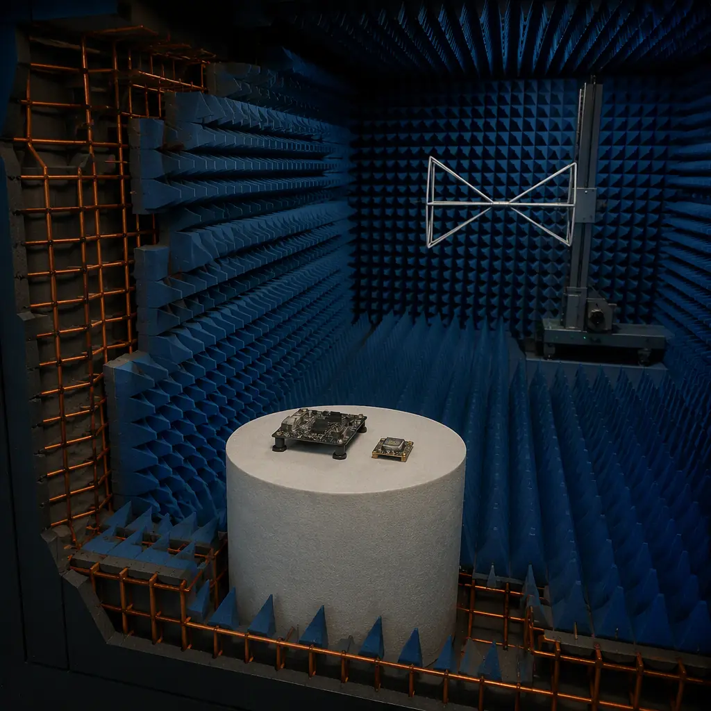
CISPR 22 / CISPR 32 and FCC Part 15 — the commercial baseline. CISPR 22 (superseded by CISPR 32 for multimedia equipment, but still referenced in many UAV component datasheets) and FCC Part 15 Subpart B are the baseline emissions standards for commercial electronic products. Both standards divide products into Class A (industrial/commercial environment — the UAV's operating environment) and Class B (residential environment — more stringent limits, typically 10 dB lower than Class A across most of the frequency range). The measurement frequency range for radiated emissions is 30 MHz to 1 GHz (CISPR 22) or 30 MHz to 6 GHz (CISPR 32, which extends upward to cover the wireless communication bands above 1 GHz). The measurement distance for radiated emissions is 10 metres for CISPR 22 Class A (3 metres for FCC Part 15) — a 10-metre measurement is 10.5 dB less stringent than a 3-metre measurement (the field strength falls off as 1/distance, which is −20 dB per decade, so the limit at 10 m is approximately 10.5 dB lower than at 3 m), but the 10-metre chamber costs $500,000–$1,500,000 to construct, so most pre-compliance testing is done at 3 metres with the limits adjusted by +10.5 dB. The conducted emissions frequency range is 150 kHz to 30 MHz, measured on the AC mains input (for equipment powered from the mains) or on the DC power input (for UAV components powered from a battery — the CISPR 25 automotive standard is sometimes referenced for DC-powered equipment, as it defines conducted emissions limits for the 150 kHz–108 MHz range on DC power lines).
Immunity standards — the other half of the EMC equation. The emissions standards ensure that the UAV's electronics do not interfere with other equipment. The immunity standards ensure that other equipment does not interfere with the UAV's electronics — and for a UAV, where a single bit error in the GPS position data or a single corrupted MAVLink packet can cause a flyaway, the immunity requirements are as critical as the emissions limits. The baseline commercial immunity standard is IEC 61000-4, a multi-part standard that defines the test methods and performance criteria for six immunity phenomena:
IEC 61000-4-2 — Electrostatic discharge (ESD): 4 kV contact discharge, 8 kV air discharge. The UAV's avionics must survive ESD events without resetting, corrupting memory or entering an undefined state. The test simulates a technician touching the UAV's exposed connectors or an antenna — the human body can accumulate 8–15 kV of static charge in dry conditions, and the discharge current waveform has a rise time of 0.7–1.0 ns with a peak current of 30 A at 8 kV (the HBM — human body model — discharge waveform specified in IEC 61000-4-2). A flight controller that resets during an ESD test at 4 kV contact discharge will reset when a technician unplugs the GPS antenna after a flight on a dry winter day — and if the UAV is powered on during that maintenance action, the reset may corrupt the flight controller's parameter memory.
IEC 61000-4-3 — Radiated RF immunity: 3 V/m or 10 V/m field strength from 80 MHz to 6 GHz, with 80% amplitude modulation at 1 kHz (the AM modulation simulates the effect of a nearby digital radio transmitter, whose carrier is modulated by the data stream — the modulation creates sidebands that couple more energy into the victim's nonlinear circuits than an unmodulated carrier). The 10 V/m level corresponds to the field strength 1 metre from a 4 W handheld radio at 400 MHz — a realistic scenario for a UAV operating near ground personnel with handheld radios or near a cellular base station with 20–40 W EIRP at 700–2,600 MHz. The UAV's flight controller, GPS receiver, telemetry radio and companion computer must all continue operating correctly — no resets, no data corruption, no loss of GPS lock — while exposed to the 10 V/m field across the full 80 MHz–6 GHz frequency range.
IEC 61000-4-4 — Electrical fast transient (EFT) / burst: 1–4 kV burst of 5/50 ns pulses at a 5–100 kHz repetition rate, coupled onto the power and signal lines. The EFT test simulates the arcing that occurs when a relay contact opens or a motor's brushes commutate — the UAV's ESCs are brushless and do not produce brush arcing, but the battery connector produces an arc when the battery is plugged in (the XT60 connector's contacts bounce for 1–5 ms during insertion, producing a burst of 50–200 V transients on the DC bus), and the avionics must survive this burst without damage. IEC 61000-4-5 — Surge: 0.5–4 kV combination wave (1.2/50 µs voltage, 8/20 µs current) on the power lines. The surge test simulates a nearby lightning strike or a power grid switching transient — less relevant for battery-powered UAVs, but relevant for the ground-based charging infrastructure. IEC 61000-4-6 — Conducted RF immunity: 3–10 V RF signal from 150 kHz to 80 MHz, coupled onto the power and signal lines through a coupling/decoupling network (CDN). This test simulates the RF currents that flow on the UAV's wiring harness when the telemetry radio transmits — the antenna's near-field induces currents on nearby conductors, and the CDN injects those currents directly into the power and signal ports to verify that the circuitry can reject them.
 Concept illustration
MIL-STD-461 — the defence threshold. For UAVs intended for defence applications, MIL-STD-461G defines the EMC requirements that supersede the commercial standards. The key test methods are CE102 (conducted emissions, power leads, 10 kHz–10 MHz), RE102 (radiated emissions, electric field, 10 kHz–18 GHz), CS114 (conducted susceptibility, bulk cable injection, 10 kHz–200 MHz) and RS103 (radiated susceptibility, electric field, 2 MHz–40 GHz at 20–200 V/m depending on the platform). The RS103 requirement of 200 V/m at 1–18 GHz for aircraft external installations is 20–40 dB more stringent than the commercial 3–10 V/m requirement — a flight controller that passes commercial radiated immunity at 10 V/m will fail MIL-STD-461 RS103 by a factor of 20 (26 dB), and the design changes required to close that gap (shielded enclosure, filtered connectors, differential signalling with twisted-pair wiring, galvanic isolation on all external interfaces) add $200–500 to the component's bill of materials and 50–150 grams to its weight. The procurement team must specify the applicable standard at the RFQ stage — upgrading a commercial design to MIL-STD-461 after the PCB is laid out requires a board respin, which adds 8–12 weeks to the programme schedule and $5,000–$15,000 in redesign and retesting costs.
PCB-level EMC design: the four rules that prevent test chamber failures
The EMC performance of a UAV avionics board is determined by four PCB design decisions, all of which are made during the schematic and layout phase — weeks or months before the first prototype reaches the EMC test chamber. The procurement team cannot directly control the supplier's PCB layout, but it can contractually require that the supplier's design documentation demonstrate compliance with a set of EMC design rules — and it can verify that compliance during the design review, before the PCB is fabricated. The four rules are: ground plane integrity, decoupling capacitor placement, trace impedance control, and stack-up specification.
Rule 1 — Ground plane integrity. The ground plane is the foundation of the PCB's EMC performance. Every signal on the board has a return current that flows through the ground plane — the return current follows the path of least impedance, which at DC is the path of least resistance (a straight line from the load to the source) but at the frequencies that matter for EMC (1 MHz and above) is the path of least inductance, which is directly underneath the signal trace. If the ground plane is continuous — a solid copper layer with no splits, no gaps and no slots — the return current stays directly under the signal trace, and the magnetic field from the forward current (in the trace) is cancelled by the magnetic field from the return current (in the plane), minimizing the loop area and therefore the radiated emissions. If the ground plane is split — a gap of 1 mm or more in the copper, created by a routing channel, a connector footprint or a via farm that cuts through the plane — the return current must detour around the split, creating a loop area that radiates as a magnetic dipole antenna. The radiated field strength from a loop of area A carrying a current I at frequency f, measured at distance d, is approximately E = (1.32 × 10⁻¹⁴ × A × I × f²) / d in volts per metre, for A in square metres, I in amperes, f in hertz and d in metres. A 10 mA current at 100 MHz (a typical clock harmonic for a 100 MHz SPI bus on a flight controller) flowing through a loop of 5 cm² (a 10 mm trace over a ground plane with a 5 mm split) radiates approximately 66 µV/m at 3 metres — well below the FCC Class A limit of 150 µV/m at 100 MHz, but the same loop carrying the 50 A of PWM current from an ESC trace at the 50th harmonic of 24 kHz (1.2 MHz — lower frequency, so E ∝ f² reduces the field, but I = 50 A is 5,000× larger) radiates approximately 0.8 µV/m at 3 metres at 1.2 MHz. The proximity of multiple such loops in the avionics bay creates the complex interference environment that desensitizes the GPS receiver. The procurement specification should require that the supplier's PCB layout demonstrate a continuous ground plane with no splits greater than 1.5 mm in width, and that any unavoidable plane splits be bridged with stitching capacitors (10–100 nF ceramic capacitors placed across the split at intervals of λ/20 at the highest frequency of concern — approximately 1.5 cm at 1 GHz, which is impractical for most splits, so the preferred solution is to eliminate the split entirely).
Rule 2 — Decoupling capacitor placement. Every digital IC on the UAV's avionics board — the STM32H7 microcontroller on the flight controller, the FPGA or CPLD on the video processing board, the comparator on the ESC's zero-crossing detection circuit — draws current in pulses that coincide with the clock edge. The STM32H7's ARM Cortex-M7 core running at 480 MHz draws approximately 200–400 mA of dynamic current, and the current demand changes from near-zero to the full value in the 200–500 ps of the clock transition. The PCB's power distribution network (PDN) must supply that current without the supply voltage sagging below the IC's minimum operating voltage — typically 3.0 V for a 3.3 V rail, giving a 300 mV margin. The inductance of the power plane and the vias between the decoupling capacitor and the IC's power pins limits the capacitor's ability to respond to the current transient: the via inductance is approximately 0.8 nH per millimetre of via length (for a 0.3 mm diameter via in a 1.6 mm thick board, the inductance is approximately 1.0–1.5 nH per via), and a 100 nF decoupling capacitor connected through two vias (VCC and GND, each contributing approximately 1.2 nH) has a total loop inductance of approximately 2.5 nH. The capacitor's self-resonant frequency (SRF) — the frequency at which the capacitor's parasitic inductance cancels its capacitance — is approximately 1 / (2π × √(LC)) = 1 / (2π × √(2.5 nH × 100 nF)) ≈ 10 MHz for a 100 nF MLCC in an 0402 package. Above 10 MHz, the capacitor looks inductive, and its impedance rises with frequency — it stops being a capacitor and starts being an inductor. The procurement specification should require that the supplier's PDN design demonstrate an impedance below 100 mΩ from DC to 500 MHz (the bandwidth of the STM32H7's current transient, which has frequency content up to approximately 0.35 / 200 ps = 1.75 GHz — the 500 MHz upper bound covers the first decade of the transient's spectrum, where most of the energy resides) through the placement of multiple decoupling capacitors in parallel: 100 nF for the mid-frequency range (1–100 MHz), 10 nF for the high-frequency range (10–500 MHz), and 1 nF for the highest-frequency range (100 MHz–1 GHz), each capacitor size providing a low-impedance path in its effective frequency range. The specific capacitor values, package sizes and placement positions should be documented in the supplier's PDN simulation report — not guessed from a reference design.
 Concept illustration
Rule 3 — Trace impedance control. The characteristic impedance of a PCB trace is determined by its width, its height above the reference plane (the dielectric thickness), and the dielectric constant of the substrate material. For a microstrip trace (a signal trace on an outer layer, with a ground plane on the adjacent inner layer), the characteristic impedance is approximately Z₀ = (87 / √(εr + 1.41)) × ln(5.98 × h / (0.8 × w + t)), where εr is the dielectric constant (approximately 4.0–4.6 for standard FR-4), h is the dielectric thickness in mils (1 mil = 0.0254 mm), w is the trace width in mils and t is the copper thickness in mils. For a 50 Ω trace on a standard 4-layer board with a 0.2 mm (8 mil) prepreg between the top layer and the inner ground plane, εr = 4.3, the required trace width is approximately 0.35 mm (14 mils) for 1 oz (35 µm) copper. If the trace width varies along its length — due to a neck-down at a connector pin, a via transition, or a component pad — the impedance discontinuity reflects a portion of the signal energy back toward the source, creating a standing wave on the trace that radiates as a transmission-line antenna. The reflection coefficient at an impedance discontinuity is Γ = (ZL − Z₀) / (ZL + Z₀), where ZL is the impedance of the discontinuity — a trace that necks down from 0.35 mm (50 Ω) to 0.20 mm (approximately 65 Ω) at a connector pin creates a reflection of Γ = (65 − 50) / (65 + 50) = 0.13, reflecting 1.7% of the signal power (−17.7 dB), which is acceptable for most digital signals but problematic for the GPS antenna's 50 Ω RF trace (where any reflection reduces the signal-to-noise ratio at the receiver input, potentially degrading the GPS acquisition sensitivity by 1–3 dB and increasing the time-to-first-fix by 10–30 seconds). The procurement specification should require that the supplier's PCB layout demonstrate controlled impedance for all RF traces (GPS antenna, telemetry radio antenna, video transmitter antenna) with a tolerance of ±10% on the characteristic impedance, verified by a time-domain reflectometer (TDR) measurement on the first-article PCB.
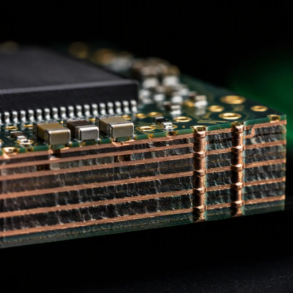
Rule 4 — Stack-up specification. The PCB's layer stack-up — the number of copper layers and the arrangement of signal, power and ground layers — determines the board's EMC performance more than any other design decision. A 2-layer board (signal on top, ground pour on bottom) has no continuous ground plane — the ground pour on the bottom layer is interrupted by signal traces that cut through it, creating the ground plane splits described in Rule 1. The minimum stack-up for a UAV avionics board with any RF or high-speed digital content is 4 layers: Signal 1 (top) — Ground (inner 1) — Power (inner 2) — Signal 2 (bottom). The Ground layer provides a continuous reference plane for the top-layer high-speed signals; the Power layer provides a low-impedance power distribution network; the bottom layer carries low-speed signals that do not require a continuous reference plane (I²C, UART at 115,200 bps or lower, CAN bus at 1 Mbps). For boards with a companion computer (NVIDIA Jetson, Raspberry Pi Compute Module) or an FPGA, 6 layers are recommended: Signal 1 — Ground — Signal 2 — Power 1 — Ground — Signal 3. The additional Ground layer provides a reference plane for the Signal 2 inner-layer traces, and the dual ground planes create a stripline configuration for the inner signal layer (the trace is sandwiched between two ground planes, which provides superior shielding compared to a microstrip trace on an outer layer — the stripline's radiated emissions are 20–40 dB lower than an equivalent microstrip at 1 GHz, because the ground planes on both sides confine the electromagnetic field). The procurement specification should require that the supplier's PCB stack-up be documented in the fabrication drawing, with the dielectric material (FR-4, with a glass transition temperature Tg of at least 130°C for standard UAV applications and 170°C for high-temperature applications — the higher Tg material resists delamination during lead-free soldering at 245–260°C), the copper weight (1 oz / 35 µm for signal layers, 2 oz / 70 µm for the Power layer if the board carries more than 10 A of total current) and the prepreg/core thickness between each layer.
System-level EMC integration: cables, shielding, filtering and grounding
A set of individually compliant PCBs does not guarantee a compliant system. The interconnects between the PCBs — the wiring harness that connects the flight controller to the GPS, the telemetry radio, the ESCs and the companion computer — create antennas that radiate the noise from one PCB into another. The avionics bay's metal or carbon fibre structure creates a resonant cavity that amplifies the emissions at its resonant frequencies. And the grounding scheme — whether the avionics share a single-point ground or a multi-point ground, and whether the ground connections between the PCBs are low-impedance at the frequencies of interest — determines whether the ground reference voltage is the same at every point in the system or whether a ground potential difference of 50–500 mV develops between the GPS receiver and the flight controller, corrupting the UART data. System-level EMC integration addresses these three coupling mechanisms: conducted coupling through the wiring harness, radiated coupling through the avionics bay cavity, and common-impedance coupling through the ground network.
Conducted coupling through the wiring harness. The wiring harness is the primary antenna for the UAV's avionics. A 20 cm wire — the typical length of a GPS-to-flight-controller UART cable — is a quarter-wave monopole antenna at 375 MHz and a half-wave dipole at 750 MHz, both of which fall within the 4G/LTE downlink band (700–2,600 MHz) and the video transmitter's operating frequency (5.8 GHz, whose 7th harmonic at 830 MHz also falls within the wire's resonant range). The wire's efficiency as an antenna — the fraction of the incident RF power that it re-radiates — depends on its impedance match to free space (377 Ω), which depends on its length relative to the wavelength. At its quarter-wave resonant frequency, the wire's radiation resistance is approximately 36 Ω, and an RF current of 1 mA at that frequency radiates approximately 36 µW of power — a small absolute number, but the GPS receiver's sensitivity is −165 dBW (3.2 × 10⁻¹⁷ W) for the L1 C/A code, and the wire radiating 36 µW (4.5 × 10⁻⁵ W) at 375 MHz is 118 dB above the GPS receiver's noise floor at 1.57542 GHz — if even 0.001% of that radiated power couples into the GPS antenna at L1 (which is 55 dB below the 375 MHz radiation), the received interference power is still 63 dB above the GPS noise floor, desensitizing the receiver.
The mitigation for conducted coupling is common-mode filtering at every connector that exits the PCB. A common-mode choke — a ferrite core with two windings, one for the signal and one for its return, wound in opposite directions — presents a high impedance to common-mode currents (the noise current that flows in the same direction on both the signal and return conductors, which is the current that radiates) while presenting a low impedance to differential-mode currents (the signal current, which flows in opposite directions on the two conductors and whose magnetic fields cancel in the ferrite core). The common-mode impedance of a ferrite choke at 100 MHz is typically 500–2,000 Ω, which attenuates the common-mode current by 20–30 dB — reducing the radiated power by a factor of 100–1,000. The procurement specification should require a common-mode choke on every signal cable that exits the avionics bay: the GPS UART cable, the telemetry radio UART cable, the CAN bus cable (if the CAN bus extends outside the avionics bay to a motor-mounted ESC or a wingtip GPS antenna) and the I²C cable to the external magnetometer. The choke should be placed within 10 mm of the connector on the PCB side — the section of wire between the choke and the connector is not filtered, and keeping it short minimizes its antenna length. For the detailed wiring-level EMI management — including the shielding, twisting and separation practices that complement the common-mode filtering — the UAV connectors, wiring and power distribution guide covers the harness-level EMI practices in full.
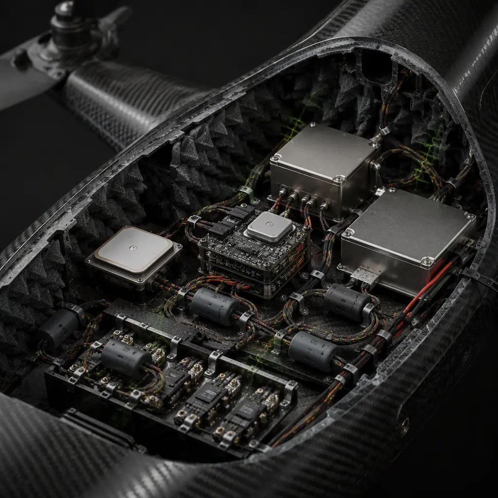
Radiated coupling through the avionics bay cavity. The avionics bay is a metal or carbon fibre enclosure that behaves as a resonant cavity at frequencies where its dimensions are integer multiples of half the wavelength. For a rectangular avionics bay measuring 150 mm × 100 mm × 50 mm, the lowest resonant frequency (the TE101 mode, where the electric field is parallel to the 150 mm dimension) is approximately f = (c / 2) × √((1/0.15)² + (0/0.10)² + (1/0.05)²) = 1.5 × 10⁸ × √(44.4 + 0 + 400) = 1.5 × 10⁸ × 21.1 = 3.17 GHz. This is within the 5.8 GHz video transmitter's 2nd harmonic at 11.6 GHz and the 4G/LTE uplink band at 1,710–1,755 MHz (the TE101 mode at 1.7 GHz — calculated for a larger bay). When the cavity resonates, the field strength at the antinode (the point of maximum field) is Q times the field strength that the source would produce in free space, where Q is the cavity's quality factor — typically 10–100 for a metal enclosure with apertures (the connector cutouts, the ventilation holes, the seams between the lid and the body). A source that produces 1 mV/m at 1 metre in free space produces 10–100 mV/m at the antinode inside a resonant cavity — and the GPS antenna, if it is mounted inside the avionics bay (a common configuration for fixed-wing UAVs and small multirotors where the GPS antenna is integrated into the flight controller PCB), sits at the antinode of the cavity resonance and sees a field strength that is 20–40 dB above the free-space value. The mitigation for cavity resonance is internal absorbing material — a ferrite tile or a carbon-loaded foam absorber placed on the interior walls of the avionics bay, which converts the RF energy into heat. A 3 mm thick ferrite absorber tile (e.g., the Laird BSR-1 or the TDK IBF series) provides 10–20 dB of absorption from 1–18 GHz, reducing the cavity Q from 50 to 5–10 and bringing the resonant field strength down to near-free-space levels. The procurement specification should require that the avionics bay's interior surfaces be lined with absorber material in the frequency ranges where the cavity dimensions create resonances that overlap with the onboard transmitters' operating frequencies and harmonics.
 Concept illustration
Common-impedance coupling through the ground network. When two PCBs share a ground connection — the flight controller and the GPS receiver both connect their ground pins to the same ground bus on the PDB — the current that flows from the ESC's ground return through the PDB's ground plane creates a voltage drop across the plane's resistance. A 2 oz copper ground plane that is 100 mm long and 50 mm wide has a DC resistance of approximately R = ρ × L / (w × t), where ρ = 1.72 × 10⁻⁸ Ω·m (copper resistivity), L = 0.1 m, w = 0.05 m and t = 70 × 10⁻⁶ m (2 oz = 70 µm), giving R = 1.72 × 10⁻⁸ × 0.1 / (0.05 × 70 × 10⁻⁶) = 0.49 mΩ. At 50 A of ESC ground return current, the voltage drop across the plane is 0.49 mΩ × 50 A = 24.5 mV — a DC offset that the 3.3 V logic can tolerate. But at the ESC's switching frequency of 48 kHz, the ground plane's impedance is dominated by inductance, not resistance: the inductance of a 100 mm × 50 mm ground plane is approximately 5–10 nH (the inductance of a wide, thin conductor is approximately L = 2 × 10⁻⁷ × l × ln(2l / (w + t)) henries, giving L ≈ 2 × 10⁻⁷ × 0.1 × ln(0.2 / 0.05007) = 2 × 10⁻⁸ × ln(4.0) = 2.8 × 10⁻⁸ H = 28 nH for a single ground plane segment). At 48 kHz, 28 nH has an impedance of 2π × 48 × 10³ × 28 × 10⁻⁹ = 8.4 mΩ — still low. But at the 500th harmonic of 48 kHz (24 MHz — the frequency that matters for the GPS L1 band, where the receiver's sensitivity is highest), 28 nH has an impedance of 2π × 24 × 10⁶ × 28 × 10⁻⁹ = 4.2 Ω — and a 50 A current at 24 MHz, though the PWM waveform's Fourier amplitude at the 500th harmonic is attenuated by approximately 1/500 = 0.002 (54 dB below the fundamental), giving a harmonic current of 50 A / 500 = 100 mA — still produces a voltage drop of 100 mA × 4.2 Ω = 420 mV across the ground plane. The GPS receiver's UART ground reference, which is connected to the same ground plane at a different point, sees a 420 mV difference from the flight controller's UART ground reference — and the UART's noise margin is 200–300 mV for a 3.3 V signal. The data is corrupted.
The mitigation for common-impedance coupling is a star-ground topology: each PCB's ground connects to a single central ground point (the PDB's battery negative terminal) through a dedicated ground wire, and the PCB grounds do not connect to each other except through that single point. The star-ground prevents the ESC's ground return current from flowing through the flight controller's ground connection — the ESC's ground current flows directly from the ESC to the central ground point, and the flight controller's ground current flows from the flight controller to the same point through a separate wire, with no shared impedance. The procurement specification should require that the wiring harness implement a star-ground topology: every PCB in the avionics stack has its own ground wire to the central ground point, and the ground pins on the signal connectors between PCBs are used for signal reference only (carrying the UART return current, which is < 10 mA, not the ESC ground return current, which is 10–50 A). The central ground point should be a copper bus bar or a heavy copper pad on the PDB, with a cross-sectional area of at least 10 mm² (equivalent to a 7 AWG wire — sufficient for 50 A continuous with a 30°C temperature rise).
Pre-compliance EMC testing: catching failures before the accredited lab
The accredited EMC test laboratory charges $1,500–$3,000 per day for a 3-metre semi-anechoic chamber and $2,500–$5,000 per day for a 10-metre fully anechoic chamber. A full commercial emissions and immunity test suite for a UAV avionics stack — radiated emissions 30 MHz–6 GHz, conducted emissions 150 kHz–30 MHz, radiated immunity 80 MHz–6 GHz at 10 V/m, conducted immunity 150 kHz–80 MHz, ESD and EFT — takes 3–5 days and costs $10,000–$25,000. If the device fails any test, the test must be repeated after the design is corrected, at an additional $10,000–$25,000 per iteration. Three iterations — one initial test that reveals the failures, one retest after the first round of corrections and one final test after the second round — can cost $30,000–$75,000 and delay the certification by 6–12 weeks. Pre-compliance testing — using low-cost equipment in the development lab to identify the failures before the accredited test — can reduce the number of accredited test iterations from three to one, saving $20,000–$50,000 and 4–8 weeks of schedule.
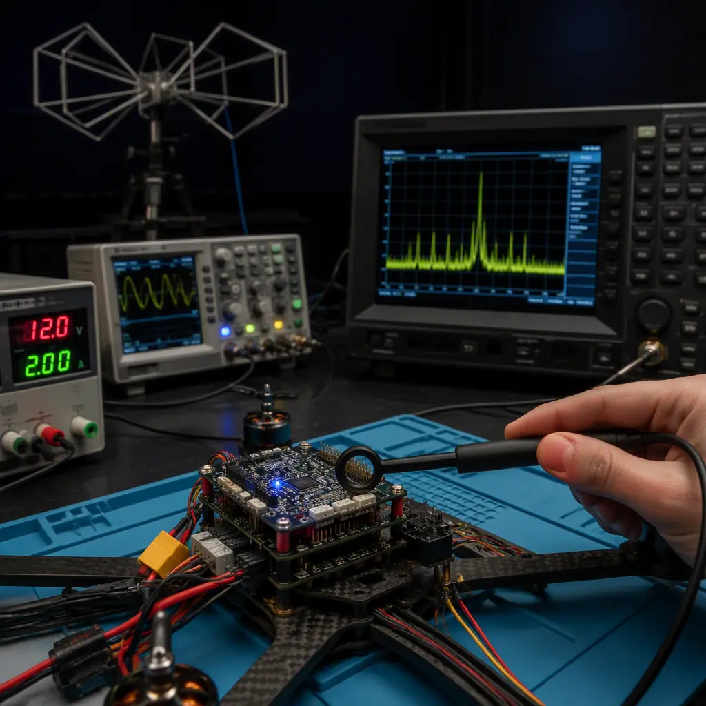
Pre-compliance radiated emissions setup. The minimum equipment for pre-compliance radiated emissions testing is: a spectrum analyzer with a frequency range of 9 kHz to 3 GHz (the Rigol DSA815-TG at $1,500, or the Siglent SSA3021X Plus at $2,000, or a used HP/Agilent ESA-series at $2,000–$4,000), a set of near-field probes (the Beehive Electronics 100-series probe set at $300–$500 — an H-field loop probe for magnetic field measurements from 30 MHz–6 GHz and an E-field monopole probe for electric field measurements from 30 MHz–6 GHz), and a calibrated antenna — a biconical antenna for 30–200 MHz ($500–$1,500) and a log-periodic antenna for 200 MHz–3 GHz ($500–$1,500), or a single broadband hybrid antenna (the Com-Power AB-900A biconilog at $3,500, covering 30 MHz–3 GHz). The total equipment cost is $3,000–$8,000 — a one-time investment that pays for itself in one avoided accredited lab retest. For the 3–6 GHz range (required for CISPR 32), add a double-ridged horn antenna ($1,000–$2,500).
The pre-compliance measurement procedure is not intended to produce results that are directly comparable to the accredited lab's results — the pre-compliance setup lacks the calibrated ground plane, the anechoic chamber, the antenna mast and turntable automation and the ambient noise control that the accredited lab provides. Instead, the pre-compliance procedure provides a relative measurement: scan the device under test (DUT) at a fixed antenna distance of 1 metre (not 3 or 10 metres — the near-field effects at 1 metre are significant at frequencies below 100 MHz, where the wavelength is > 3 metres, but the pre-compliance measurement's purpose is to compare before-and-after design changes, not to assert absolute compliance), record the emissions spectrum, then repeat the scan after each design change and compare. A design change that reduces the emissions by 6–10 dB at the failing frequency in the pre-compliance setup will reduce the emissions by a similar amount in the accredited lab — the absolute levels differ, but the relative improvement is consistent. The key is consistency: the DUT's position, orientation, cabling and operating mode must be identical between scans, documented with photographs and a measurement procedure, so that the pre-compliance results are reproducible.
 Concept illustration
Pre-compliance conducted emissions setup. The equipment for conducted emissions pre-compliance is a line impedance stabilization network (LISN) — a passive network that provides a standardized impedance (50 Ω) to the DUT's power input and couples the noise voltage on the power line to the spectrum analyzer's 50 Ω input. A single-channel LISN for DC power (the Tekbox TBOH01 at €450, or the Com-Power LI-125A at $900) covers the 150 kHz–30 MHz frequency range (CISPR 22 conducted emissions) and the 100 kHz–108 MHz range (CISPR 25 for automotive/DC applications). The measurement procedure: connect the DUT's DC power input to the LISN's EUT port, connect the battery to the LISN's input port, connect the LISN's RF output to the spectrum analyzer, and scan the 150 kHz–30 MHz range with the spectrum analyzer's resolution bandwidth set to 9 kHz (the CISPR-specified bandwidth for conducted emissions measurements). The pre-compliance conducted emissions measurement is more accurate than the pre-compliance radiated emissions measurement because the LISN provides a controlled impedance, and the results at the pre-compliance bench are typically within 3–6 dB of the accredited lab's results — close enough to identify failures with high confidence. For the flight controller and the companion computer, which have switching regulators on board (the 5 V and 3.3 V buck converters that step down the battery voltage), the conducted emissions scan will typically show peaks at the switching regulator's fundamental frequency (500 kHz–2 MHz for a typical buck converter) and its harmonics up to 30 MHz — and adding an LC filter (a series inductor of 10–47 µH and a shunt capacitor of 10–100 µF on the regulator's input) can reduce the conducted emissions at the fundamental by 20–30 dB.
Pre-compliance immunity testing — radiated. Radiated immunity pre-compliance requires an RF signal generator (the Rigol DSG815 at $900, covering 9 kHz–1.5 GHz, or the Siglent SSG3021X at $1,800, covering 9 kHz–2.1 GHz), an RF power amplifier (the Mini-Circuits ZHL-42W+ at $1,500, covering 10–4,200 MHz at 30–40 W output, or a used amplifier from AR/Rohde & Schwarz at $2,000–$5,000) and an antenna (the same broadband antenna used for emissions testing can be used for immunity, with the power amplifier driving the antenna instead of the spectrum analyzer receiving from it). The field strength at the DUT is estimated from the amplifier's output power, the antenna's gain and the distance: E (V/m) = √(30 × P × G) / d, where P is the net power delivered to the antenna (watts), G is the antenna's numeric gain (not dBi — G = 10^(dBi/10)) and d is the distance in metres. A 10 W amplifier driving an antenna with 6 dBi gain (G = 4) at 1 metre produces E = √(30 × 10 × 4) / 1 = √(1,200) = 34.6 V/m — sufficient for pre-compliance testing at the commercial 10 V/m level, with margin. The test sweeps the frequency range while monitoring the DUT for malfunctions: GPS lock status (monitor the NMEA sentences on the UART — a loss of lock is indicated by the $GPGGA sentence's fix quality field changing from 1 or 2 to 0), telemetry link quality (monitor the RSSI — a 10 dB drop indicates that the telemetry receiver is being desensitized by the immunity field), and flight controller status (monitor the heartbeat MAVLink message — a missing heartbeat for more than 500 ms indicates that the flight controller has reset). The pre-compliance immunity test will typically fail at the GPS L1 frequency (1.575 GHz) if the GPS antenna's preamplifier is not adequately shielded, at the 2.4 GHz ISM band (if the telemetry radio's front-end filter is insufficient) and at the 4G/LTE downlink bands (700–2,600 MHz, where the companion computer's DDR memory bus radiates harmonics that couple into the RF front-ends of the GPS and telemetry receivers).
EMC procurement specification: what the RFQ must require
The procurement specification translates the EMC standards, design rules and testing methodology into contractual requirements that the supplier must meet. The specification must be specific enough that the supplier's compliance can be verified at incoming inspection, and it must be realistic — requiring MIL-STD-461 RS103 at 200 V/m from a $50 commercial GPS module will result in no-bid responses from all qualified suppliers. The following specification sections are recommended for inclusion in the RFQ for each UAV avionics subassembly.
Applicable standards. List the specific EMC standards that the component must comply with, including the test method, the frequency range, the limit and the performance criterion. For a commercial flight controller intended for the European and U.S. markets: "The flight controller shall comply with the radiated emissions limits of CISPR 32 Class A, 30 MHz–6 GHz, measured at 3 metres per the method of CISPR 16-2-3. The flight controller shall comply with the conducted emissions limits of CISPR 32 Class A, 150 kHz–30 MHz, measured on the DC power input per the method of CISPR 16-2-1 with a 50 µH LISN. The flight controller shall comply with the radiated immunity requirements of IEC 61000-4-3 at 10 V/m, 80 MHz–6 GHz, with 80% AM modulation at 1 kHz, performance criterion A (no degradation of performance during or after the test — the flight controller shall not reset, shall not corrupt stored parameters and shall continue to output valid MAVLink heartbeat messages at the specified rate throughout the test). The flight controller shall comply with the ESD immunity requirements of IEC 61000-4-2 at 4 kV contact discharge and 8 kV air discharge, performance criterion B (temporary degradation of performance during the test is acceptable, provided the flight controller self-recovers to normal operation within 10 seconds after the discharge without operator intervention — the flight controller shall not require a power cycle to recover)." The performance criteria for each test (A, B or C per the IEC 61000-4 series definitions) must be specified — the supplier and the procurement team must agree on what constitutes a pass before the test is performed, because a disagreement about whether the DUT's behaviour during the test constitutes a failure is a common source of disputes between suppliers and buyers in the UAV industry.
PCB design documentation. Require the supplier to provide the PCB stack-up drawing (layer count, material, copper weight, dielectric thickness, Tg), the impedance control table (trace width and spacing for each controlled-impedance net — GPS antenna RF trace, telemetry radio RF trace, USB 2.0/3.0 differential pairs, DDR memory bus), and the PDN impedance simulation report (the simulated impedance vs frequency curve for each power rail, demonstrating that the impedance is below the target of 100 mΩ from DC to 500 MHz for the core voltage rails and below 500 mΩ for the I/O voltage rails). The procurement team does not need to be expert in PDN simulation — but the existence of the simulation report is itself a signal that the supplier has considered EMC during the design phase, and a supplier that cannot produce a PDN simulation report is a supplier that will discover the EMC problems in the test chamber, not in the design review.
EMC test report. Require the supplier to provide an EMC test report from an ISO/IEC 17025 accredited laboratory, covering the specific standards and test methods listed in the applicable standards section. The test report must include: the laboratory's accreditation certificate, the test equipment list (with calibration due dates — equipment that is overdue for calibration invalidates the test results), the test setup photographs (showing the DUT's orientation, cabling and operating mode — the procurement team should verify that the setup matches the actual UAV installation, because a DUT tested with shielded cables in a laboratory setup may not represent the DUT as installed in the UAV with unshielded cables), the ambient noise floor measurement (the spectrum analyzer trace with the DUT powered off, to demonstrate that the ambient noise is at least 6 dB below the limit line — if the ambient noise is within 6 dB of the limit, the test results are inconclusive because the ambient noise may be at or above the limit, masking the DUT's actual emissions), and the test data (tabular and graphical, with the limit line overlaid on the measured emissions trace). The test report must be dated within 24 months of the component's delivery date — EMC performance can degrade over time as the supplier makes cost-reduction changes to the design (replacing a multilayer ceramic capacitor with a cheaper equivalent that has higher ESR, reducing the ground plane copper thickness from 2 oz to 1 oz, eliminating a ferrite bead that "wasn't needed" based on a single passing test), and a test report that is more than 24 months old may not represent the current production design.
Production consistency. Require that the supplier implement a production EMC consistency check: a simplified radiated emissions measurement (a near-field probe scan at three defined positions on the PCB, with the spectrum analyzer set to peak-hold mode across three frequency bands — 30–200 MHz, 200–1,000 MHz and 1,000–3,000 MHz) performed on every production unit, or on a statistical sample of 1 unit per 100 produced. The purpose of the production consistency check is not to verify compliance with the standard (which the accredited lab test already did) but to detect production variations that would cause a previously compliant design to become non-compliant — a change in the decoupling capacitor's dielectric material (the supplier's purchasing department switched from a Murata GRM series to a cheaper Yageo CC series without notifying the engineering team), a PCB laminate change (a different FR-4 supplier with higher dielectric loss, which changes the trace impedance and the board's resonant frequencies), or a soldering defect (a cold solder joint on a ground via that increases the ground inductance by 10–50×). The production consistency check is a $500–$1,000 investment in equipment (a spectrum analyzer and a near-field probe set) that prevents a $10,000–$25,000 accredited lab test failure when the non-compliant production unit reaches the certification stage. For the supplier evaluation and audit criteria that the procurement team should use to verify that the supplier's production process can maintain EMC consistency — including the IPC-A-610 Class 3 acceptance criteria and the first-article inspection requirements — the UAV supplier evaluation checklist covers the quality system audit framework.
For the radio frequency-specific certification requirements — the FCC Part 15 intentional radiator authorization, the ETSI EN 300 328 for 2.4 GHz equipment and the radio equipment directive (RED) 2014/53/EU for the European market — the UAV RF communication systems guide covers the transmitter-specific compliance requirements that apply in addition to the unintentional radiator EMC requirements covered in this article. For the system-level integration validation — the end-to-end test that verifies the avionics stack operates without EMC-induced failures in a representative UAV configuration — the UAV propulsion testing and validation guide covers the acceptance test procedures that include an EMC checkout (power-on all transmitters and verify GPS lock, telemetry link quality and flight controller stability with the motors at idle, 50% throttle and full throttle). For the PCB-level design practices that affect EMC through the power distribution network — the ground plane design, the decoupling strategy and the power rail filtering — the UAV connectors, wiring and power distribution guide covers the PDB and wiring harness design that connects the EMC-compliant PCBs into a system.
Explore custom engineering Back to Blog
Continue Reading

UAV Certification & Compliance Guide
The full regulatory documentation package — CE Declaration of Conformity, FCC Grant of Equipment Authorization, NDAA Section 848 compliance and the supplier certification checklist that complements the EMC test report.
UAV RF Communication Systems Guide
The transmitter-specific compliance requirements — FCC Part 15 intentional radiator authorization, ETSI EN 300 328 for 2.4 GHz and the RED 2014/53/EU directive — that apply in addition to the EMC requirements covered here.

UAV Connectors, Wiring & Power Distribution
The harness-level EMI management practices — shielding, twisting, physical separation and connector grounding — that complement the PCB-level and system-level EMC design covered in this article.

UAV Supplier Evaluation Checklist
How to audit a supplier's production EMC consistency — the IPC-A-610 Class 3 acceptance criteria, the first-article inspection and the lot traceability standard that maintains EMC compliance across production batches.

UAV Propulsion Testing & Validation
The acceptance test procedures that include an EMC checkout — verifying GPS lock, telemetry link quality and flight controller stability across the full throttle range before the UAV leaves the integration bench.