
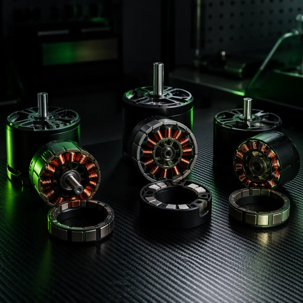
A brushless motor's nameplate — 400 KV, 12N14P, 6S, 920 g thrust at 50% throttle — tells you approximately 30% of what you need to know to select the right motor for an industrial UAV. The remaining 70% is in the electromagnetic topology: the back-EMF waveform shape (trapezoidal vs sinusoidal), the slot/pole combination (which determines the cogging torque, the torque ripple frequency and the winding factor), the magnet grade and geometry (which determine the air-gap flux density and the demagnetisation temperature), the winding configuration (concentrated vs distributed, which determines the harmonic content of the stator MMF), and the lamination material and thickness (which determine the iron losses at the operating frequency). A motor that produces 2.5 kg of thrust at 8.0 g/W on a test bench with a regulated DC power supply may produce 2.3 kg at 7.2 g/W when driven by an ESC that switches at 24 kHz with 20 ns of dead time — the 10% efficiency loss is the difference between the motor's electromagnetic efficiency (which the test bench measures) and the motor-drive system efficiency (which is what matters in flight).
For the broader propulsion system architecture — the KV selection methodology, the propeller matching process and the thrust-to-weight ratio calculation that determines whether the motor sizing is correct for the airframe — the UAV powertrain matching guide covers the system-level integration. For the ESC firmware and drive strategy that determines how the motor's back-EMF interacts with the commutation algorithm — the ESC firmware selection guide covers the FOC, BLHeli_32 and AM32 drive options. This article focuses on the motor itself: the electromagnetic architecture, the material choices and the procurement specifications that separate a motor that delivers 8.5 g/W at hover from one that delivers 6.5 g/W at the same KV, the same stator volume and the same nameplate thrust.
Motor topology fundamentals: what the three architectures actually are
The three motor topologies — BLDC, PMSM and PMAC — are all permanent-magnet synchronous machines: a rotor carrying permanent magnets rotates inside a stator carrying copper windings, and the rotor's magnetic field locks to the stator's rotating magnetic field. They differ in the shape of the magnetic field — specifically, the shape of the back-EMF waveform that the rotating magnets induce in the stator windings — and in the winding distribution that produces the stator's magnetic field. The back-EMF waveform shape determines which commutation strategy the ESC must use to extract maximum torque per ampere from the motor, and the winding distribution determines the harmonic content of the torque — the difference between a smooth torque output (PMSM with sinusoidal back-EMF and distributed winding) and a torque output with 5–15% ripple at the commutation frequency (BLDC with trapezoidal back-EMF and concentrated winding).
BLDC (brushless DC, trapezoidal back-EMF). The stator windings are concentrated — each coil is wound around a single stator tooth — and the magnets are shaped (or the rotor is designed) to produce a back-EMF waveform that is approximately trapezoidal: the voltage rises linearly as the magnet pole sweeps across the coil, holds constant while the magnet pole is fully aligned with the coil, and falls linearly as the magnet pole sweeps away. The ESC drives the motor with six-step (block) commutation: at any instant, two of the three phases are energised — one high-side MOSFET sourcing current, one low-side MOSFET sinking current — and the third phase is floating, its back-EMF voltage used by the ESC's zero-crossing detection circuit to determine when to commutate to the next step. Six-step commutation energises each phase for 120 electrical degrees out of every 180 — the motor produces torque for two-thirds of each electrical cycle, and during the remaining one-third (the commutation gap), the torque drops to near zero as the current transfers from one phase pair to the next.
The torque ripple of a six-step-driven BLDC motor is 10–15% of the average torque at the commutation frequency, which is 6× the electrical frequency (6 commutations per electrical cycle). For a 12N14P motor running at 4,800 RPM (the hover RPM of a 400 KV motor on 6S with a 15-inch propeller), the electrical frequency is 560 Hz (4,800 RPM × 7 pole pairs / 60), and the commutation frequency is 3,360 Hz. A 3,360 Hz / 10–15% torque ripple is a 3.36 kHz vibration that couples into the airframe through the motor mount — and if the airframe has a structural resonance near 3.36 kHz (a typical carbon fiber arm's first bending mode for a 650 mm quadcopter is 80–150 Hz, not 3.36 kHz, so the direct mechanical coupling is usually not resonant), the primary problem is not structural vibration but acoustic noise and the torque ripple's interaction with the flight controller's rate controller. The flight controller samples the gyroscope at 8 kHz — the 3.36 kHz ripple is below the Nyquist frequency of 4 kHz, so it is aliased into the rate controller's passband as a 640 Hz signal (8 kHz − 3.36 kHz − 4 kHz = 640 Hz), and the rate controller's D-term amplifies this 640 Hz noise, injecting high-frequency oscillations into the motor outputs that reduce the effective control bandwidth by 10–20%.
 Concept illustration
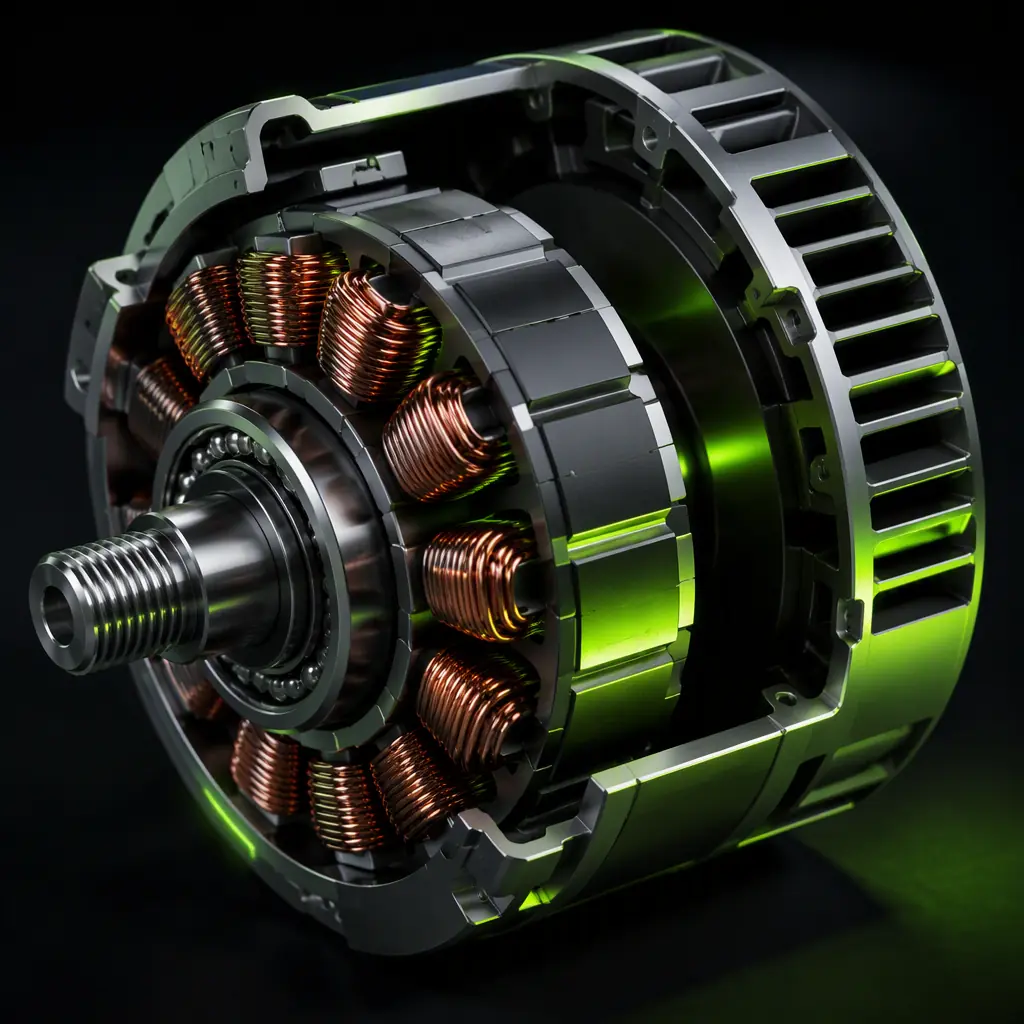
PMSM (permanent magnet synchronous motor, sinusoidal back-EMF). The stator windings are still concentrated (wound around individual teeth), but the magnet shape and the stator tooth geometry are designed to produce a back-EMF waveform that is approximately sinusoidal — the voltage varies smoothly as a sine function of the rotor angle, with less than 5% total harmonic distortion (THD) in the back-EMF waveform. The ESC drives the motor with field-oriented control (FOC): it measures the phase currents with shunt resistors or Hall-effect sensors, transforms them into the rotating d-q reference frame (the direct axis aligned with the rotor's magnetic field, the quadrature axis 90 electrical degrees ahead), and controls the d-axis current (which produces no torque — it magnetises or demagnetises the rotor) and the q-axis current (which produces torque) independently. The FOC algorithm maintains the stator current vector at exactly 90 electrical degrees ahead of the rotor flux vector at all times — the optimal angle for maximum torque per ampere — regardless of the rotor speed, the load torque and the DC bus voltage.
The result is a torque output with less than 2% ripple — a 5–10× improvement over six-step BLDC — because the current never drops to zero during commutation: all three phases are driven continuously with sinusoidal currents that sum to zero at every instant. The cost of this smoothness is the FOC controller's computational complexity — a 32-bit ARM Cortex-M4 running at 168 MHz with a floating-point unit, executing a Park transform, a Clarke transform, two PI current control loops and a space-vector PWM modulation at 24–48 kHz — and the requirement for phase current sensing (at least two low-side shunt resistors or inline current sensors, adding $1–3 to the ESC BOM). For a survey UAV carrying a $25,000 Phase One camera that requires less than 0.5 pixels of motion blur at 1/2000 second shutter speed — which translates to less than 0.005 degrees of angular vibration at the camera mount — the $3 current sensor and the FOC firmware are not a cost; they are an insurance policy on a $25,000 payload.
PMAC (permanent magnet AC, sinusoidal back-EMF with distributed winding). The stator windings are distributed — each coil spans multiple stator teeth, typically with a short-pitched winding (the coil pitch is less than the full pole pitch, e.g. a 5/6 pitch factor) — and the back-EMF is inherently sinusoidal with less than 2% THD without requiring magnet shaping. The distributed winding produces a stator MMF (magnetomotive force) that is much closer to a pure sinusoid than the concentrated winding of a BLDC or a PMSM, because the spatial harmonics of the individual coil MMFs partially cancel when the coils are distributed across multiple slots. The penalty is the end-winding length — the copper that connects one side of a coil to the other, which does not contribute to torque production but adds resistance (I²R loss) and weight — which is 30–50% longer in a distributed-winding motor than in a concentrated-winding motor of the same stator diameter. A distributed-winding PMAC motor of the same stator volume as a concentrated-winding PMSM will have 5–10% higher copper loss (because of the longer end windings) but 50–80% lower torque ripple (because of the purer sinusoidal MMF), and the procurement decision is whether the application values efficiency or smoothness.
PMAC motors are rare in multirotor UAVs below the 10 kg payload class — the weight penalty of the longer end windings is difficult to justify on an aircraft where every gram of motor weight costs approximately 0.3–0.5 grams of battery weight to maintain the same hover endurance — but they are common in fixed-wing UAV propulsion (where the motor runs at a constant RPM for cruise, and the 50–80% lower torque ripple translates to lower acoustic noise and lower vibration-induced fatigue on the motor mount) and in helicopter UAV main rotor drives (where the distributed winding's higher thermal mass and lower current density provide better tolerance for the sustained high-power operation of a helicopter in hover, which is fundamentally less efficient than a multirotor in hover because the rotor disk loading is lower and the induced power is higher).
Slot/pole combinations: the geometry that determines cogging torque and winding factor
The slot/pole combination — written as Ns/Np, where Ns is the number of stator slots and Np is the number of rotor magnet poles — is the single most important geometric parameter of a UAV motor, because it determines the cogging torque (the torque required to turn the unenergised motor, which produces a vibration at the cogging frequency), the winding factor (the fraction of the magnetic flux that the winding actually links, which determines the torque constant Kt in Nm/A), and the torque ripple frequency and amplitude. The following slot/pole combinations cover approximately 95% of the industrial UAV motor market:
12N14P (12 slots, 14 poles). This is the most common configuration for multirotor UAV motors in the 200–600 KV range with stator diameters of 35–50 mm, used on platforms from 2 kg (5-inch) to 15 kg (12S heavy-lift). The least common multiple (LCM) of 12 and 14 is 84 — the cogging torque has 84 steps per mechanical revolution, and the cogging torque amplitude is approximately 1–3% of the rated torque (low enough that the motor can be turned by hand without noticeable detent, but not zero — a 12N10P motor has an LCM of 60, producing 40% higher cogging torque). The winding factor for the fundamental harmonic is 0.933 (93.3% of the available flux is linked by the winding — an excellent value, close to the theoretical maximum of 0.955 for a 12-slot concentrated winding). The torque ripple frequency is 84× the mechanical frequency (14 poles × 6 commutations per electrical cycle = 84 torque pulses per revolution), which at 4,800 RPM is 6,720 Hz — safely above the flight controller's 8 kHz gyroscope sampling rate (the Nyquist frequency is 4 kHz, and 6,720 Hz aliases to 1,280 Hz, which the rate controller's low-pass filter attenuates by 20–30 dB).
24N28P (24 slots, 28 poles). This configuration, found in larger low-KV motors (80–150 KV) for heavy-lift platforms with stator diameters of 80–100 mm, doubles the slot and pole count of the 12N14P design. The LCM is 168 — the cogging torque has 168 steps per revolution, with an amplitude of less than 1% of the rated torque (essentially undetectable by hand). The winding factor is 0.933 (identical to 12N14P — the winding factor depends on the slots-per-pole-per-phase ratio, which is 12/(14/3) = 2.57 for 12N14P and 24/(28/3) = 2.57 for 24N28P). The torque ripple frequency is 168× the mechanical frequency, which at 2,400 RPM (the hover RPM of a 100 KV motor on 12S with a 30-inch propeller) is 6,720 Hz — the same as the 12N14P motor at 4,800 RPM, because doubling the pole count halves the RPM for the same electrical frequency. The practical advantage of 24N28P over 12N14P is the lower current per slot — with twice the number of slots, each slot carries half the current, reducing the I²R loss per slot by 75% (half the current, squared, is one-quarter the loss) and allowing the motor to operate at higher continuous power without exceeding the winding temperature limit.
 Concept illustration
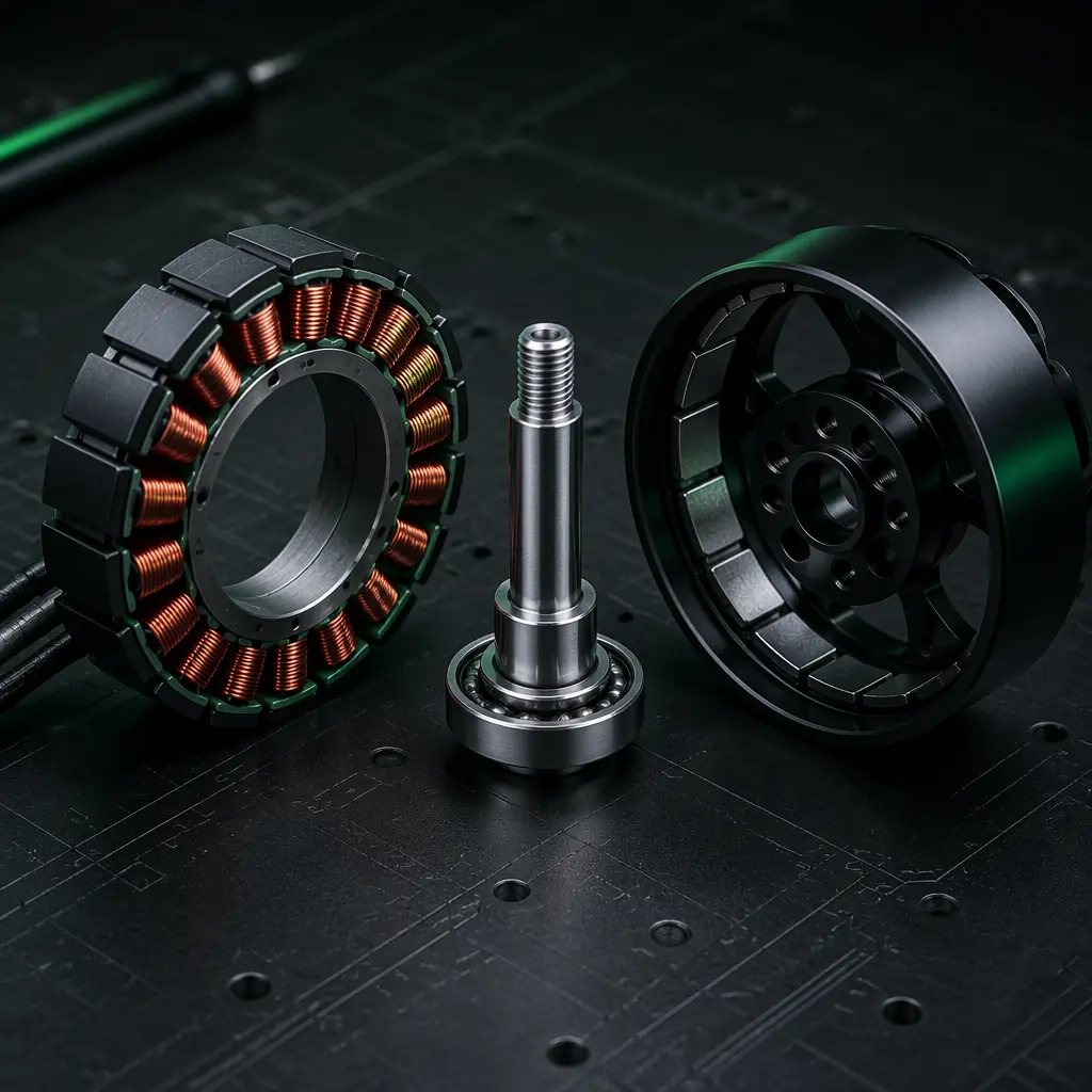
18N24P (18 slots, 24 poles). This configuration is used in motors designed for FOC drive with sinusoidal back-EMF, where the goal is to minimise the harmonic content of the back-EMF rather than to maximise the winding factor. The winding factor for the fundamental harmonic is 0.945 (slightly higher than 12N14P's 0.933), but the winding factor for the 5th and 7th harmonics — the dominant torque ripple harmonics in a concentrated-winding motor — is 0.14 and 0.10 respectively (compared to 0.50 and 0.30 for 12N14P), meaning the 5th and 7th harmonic torque ripple amplitudes are 70–80% lower. An 18N24P motor driven by FOC produces less than 1% torque ripple — the mechanical output is smooth enough that a gimbal-mounted camera cannot detect the motor's commutation in the video footage, which is the practical definition of "good enough" for professional cinematography and precision survey applications.
The procurement rule for slot/pole selection is straightforward: if the UAV carries a vibration-sensitive payload — a gimbal-mounted camera, a LiDAR scanner, a spectrometer that requires sub-pixel pointing stability — specify a motor with an LCM of ≥ 84 and a winding factor for the 5th and 7th harmonics of ≤ 0.20. This typically means 12N14P or 24N28P for BLDC/PMSM motors, or 18N24P for motors specifically designed for FOC. If the UAV carries a non-vibration-sensitive payload — a spray system, a delivery box, a drop mechanism — the slot/pole combination is not a primary procurement criterion; the efficiency, the weight and the thermal behaviour are more important.
NdFeB magnet grades: N42 vs N48 vs N52 — and the demagnetisation temperature that limits them
The permanent magnets in a UAV motor rotor are sintered NdFeB (neodymium-iron-boron), graded by their maximum energy product (BHmax in MGOe) and their intrinsic coercivity (Hci in kOe). The grade designation — N42, N48, N50, N52 — indicates the BHmax: N52 has a BHmax of 50–53 MGOe, approximately 24% higher than N42's 40–43 MGOe. A higher BHmax means the magnet produces a higher air-gap flux density for the same magnet volume — a motor with N52 magnets produces approximately 10–12% more torque per ampere than the same motor with N42 magnets (the 24% increase in BHmax translates to a ~10–12% increase in torque because the magnetic circuit's reluctance — the stator teeth, the air gap and the back iron — limits the flux, and the magnet is only one component of the total magnetic circuit).
The procurement question is not "N52 is better, so specify N52" — it is "does the 10–12% torque improvement justify the 30–50% price premium and the 20–40°C lower maximum operating temperature of N52 compared to N42?"
Temperature ratings and demagnetisation. NdFeB magnets have a maximum operating temperature above which they begin to permanently demagnetise — the coercivity drops, and the magnet cannot recover its full magnetisation when it cools. The temperature rating is indicated by a letter suffix: N42 (80°C maximum), N42SH (150°C), N42UH (180°C), N42EH (200°C). N52 magnets are available up to N52SH (150°C); N52UH and N52EH are not commercially available because the heavy rare-earth elements (dysprosium and terbium) that increase the coercivity also reduce the remanence, and the trade-off between coercivity and remanence becomes unfavourable for N52 at the UH and EH grades. A UAV motor winding at 140°C — a typical sustained hover temperature for a 12S motor drawing 25 A continuous — transfers heat through the stator laminations to the air gap, and the magnets on the rotor bell see 110–130°C depending on the air gap thickness and the rotor's centrifugal fan airflow. N42SH (150°C rated) has a 20–40°C safety margin; N52 (80°C rated, no heavy rare-earth) is operating 30–50°C above its maximum rated temperature and is permanently demagnetising at 0.5–2% per flight hour. A motor that has lost 10% of its magnet strength produces 10% less torque per ampere — the same hover thrust requires 11% more current, the I²R loss increases by 23%, the winding temperature increases further, and the demagnetisation accelerates. This is a positive-feedback failure mode that a procurement engineer prevents by specifying the correct magnet grade and temperature rating, not by assuming that "N52 = best."
For industrial UAVs where sustained hover is the dominant operating condition, specify N42SH or N48SH (150°C rated) as the minimum magnet grade. N52SH — if available from the motor supplier — is acceptable but rarely justified by the 10–12% torque improvement, because the motor's continuous power rating is usually limited by the winding temperature, not the magnet flux. N52 (no temperature suffix) is unacceptable for any UAV motor that operates above 80°C winding temperature — which is essentially all UAV motors in sustained hover, because the winding temperature of a motor producing 200–500 W of mechanical power in a 25°C ambient is 90–130°C after 5–10 minutes of hover, regardless of the motor's efficiency.
Efficiency maps: where the motor actually operates in flight — not where it peaks on the datasheet
A motor datasheet will quote a peak efficiency — typically 85–92% — at a specific operating point: usually 50–80% of the maximum throttle, at a specific voltage and with a specific propeller load. The motor in flight never operates at this point for more than a few seconds during climb-out. The motor in hover operates at 35–50% throttle (the exact percentage depends on the thrust-to-weight ratio — a UAV with 2:1 thrust-to-weight hovers at 50% throttle; a UAV with 2.5:1 hovers at 40%), and at this partial-load condition, the motor's efficiency is 5–15 percentage points lower than the peak efficiency. A motor with 90% peak efficiency at 80% throttle may deliver 78% efficiency at 40% throttle — the difference is the fixed losses (iron losses from the alternating magnetic field in the stator laminations, which are proportional to the electrical frequency and do not decrease with load) that dominate the total losses at partial load.
 Concept illustration
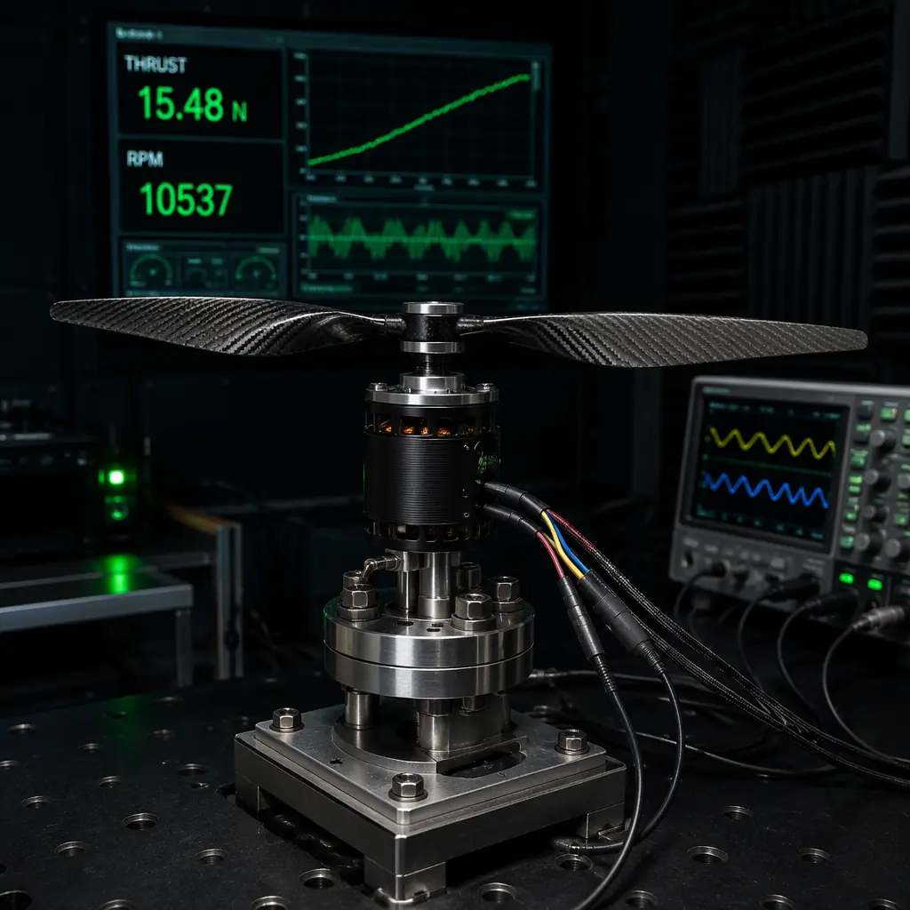
The procurement specification should request the motor's efficiency map across the 20–100% throttle range at the intended battery voltage, with the intended propeller — not just the peak efficiency point. A motor supplier that cannot provide an efficiency map (measured on a dynamometer, not computed from a finite-element model) is a supplier that has not characterised the motor's performance, and the procurement engineer is buying a motor whose partial-load efficiency is unknown. The alternative — buying a motor based on the peak efficiency and discovering in flight test that the hover endurance is 15% below the calculated value — costs far more than the dynamometer test.
For the KV selection methodology that determines the motor's operating point on the efficiency map — including the relationship between KV, battery voltage and propeller load that sets the hover RPM — the UAV motor KV selection guide covers the RPM-per-volt fundamentals, the stator size vs KV trade-off and the propeller matching calculation. For the propeller that determines the load torque at the hover RPM — and therefore the current draw and the motor's position on its efficiency map — the UAV propeller selection guide covers the diameter, pitch and blade count decisions.
Winding configuration: concentrated vs distributed, single-strand vs multi-strand
The winding configuration determines the copper fill factor — the percentage of the stator slot cross-section that is occupied by copper (the rest is slot liner insulation, air gaps between strands and the varnish that bonds the strands together) — and the AC copper loss (the increase in winding resistance at high frequency due to the skin effect and the proximity effect, which cause the current to crowd toward the surface of each strand and toward the strands closest to the slot opening). A motor with a 60% copper fill factor has 40% more resistance — and 40% more I²R loss — than a motor with an 84% fill factor, all else being equal. The fill factor is determined by the winding technique (hand-wound vs machine-wound, single-strand vs multi-strand) and the slot geometry (a parallel-sided slot allows a higher fill factor than a tapered slot, but a tapered slot reduces the tooth-tip flux leakage and improves the torque production).
Single-strand winding. Each turn of the coil is a single copper wire — typically 0.8–1.2 mm diameter — wound around the stator tooth. The fill factor is 45–60% because the round wire leaves air gaps between adjacent turns (the maximum theoretical fill factor for round-wire winding in a rectangular slot is π/4 ≈ 78.5%, and practical hand-wound motors achieve 70–85% of this theoretical maximum). The AC loss is low at UAV motor operating frequencies (the skin depth in copper at 560 Hz is 2.8 mm — thicker than the 0.8–1.2 mm wire diameter — so the skin effect is negligible, and the proximity effect is small because the number of strands per slot is small). Single-strand winding is standard for motors in the 200–600 KV range with stator diameters of 35–50 mm.
Multi-strand winding. Each turn consists of multiple thin wires in parallel — typically 4–10 strands of 0.3–0.5 mm diameter — wound together as a bundle. The fill factor is 65–80% because the thin strands pack more efficiently into the slot than a single thick strand. The AC loss is higher than single-strand winding because the proximity effect increases with the number of strands — adjacent strands carrying current in the same direction produce magnetic fields that push the current toward the outer strands, effectively increasing the AC resistance by 5–15% at 560 Hz for a 10-strand bundle of 0.3 mm wires. The multi-strand approach is used in motors where the slot is deep and narrow (a high slot depth-to-width ratio, which a single thick strand cannot fill efficiently) or where the motor is designed for FOC drive at high PWM frequencies (where the PWM frequency — 24–48 kHz — is high enough that the skin depth is 0.3–0.4 mm, and the single 1.0 mm strand would suffer from significant skin-effect loss at the PWM frequency).
The procurement specification should require the motor supplier to disclose the winding configuration (single-strand or multi-strand, strand diameter, number of strands in parallel) and the measured phase-to-phase resistance at 20°C. The measured resistance — combined with the motor's Kv (RPM/V) and the motor's mass — is sufficient to estimate the motor's efficiency at any operating point using the standard motor model (Kv, Rm, Io — the no-load current, which represents the iron losses and the bearing friction), and the procurement engineer can calculate the expected hover endurance without trusting the supplier's efficiency claims.
Procurement specification: what to put on the UAV motor RFQ
The following checklist translates the topology analysis into procurement specification items. Each item is accompanied by the pass/fail criterion and the reasoning — the supplier either demonstrates compliance or does not, and the procurement decision is based on demonstrated performance rather than marketing claims.
Topology and geometry. Motor type: outrunner (the rotor rotates outside the stator — this is the standard configuration for UAV propulsion because the larger rotor diameter produces higher torque per unit of motor mass). Slot/pole combination: 12N14P (standard), 24N28P (heavy-lift) or 18N24P (FOC-optimised). The supplier must specify the slot/pole combination in the datasheet; a motor that does not disclose the slot/pole count is assumed to be an 12N14P design with unverified winding factor. Stator lamination material: 0.2 mm or 0.35 mm silicon steel (M19, M15 or B35A300 grade) — the lamination thickness determines the iron loss at the operating frequency; 0.35 mm is acceptable for motors operating below 1,000 Hz electrical frequency, 0.2 mm is recommended for motors operating above 1,000 Hz (high-KV motors on high-voltage batteries).
Magnet specification. NdFeB grade: N42SH minimum (150°C rated). N48SH or N50SH preferred if the price premium is less than 15%. N52SH acceptable but usually not cost-justified. The supplier must provide the magnet grade certificate from the magnet manufacturer — not the motor supplier's in-house test — verifying the BHmax and the Hci at 20°C and at 150°C. A motor supplier that cannot provide the magnet certificate is assumed to be using N35 or N38 (80°C rated, the lowest-cost NdFeB grades) regardless of what the datasheet claims — because the price difference between N35 and N42SH to the motor manufacturer is approximately $0.50–1.00 per motor, and a supplier that will not prove it is using the specified magnet grade is saving that $0.50–1.00 at the expense of the motor's high-temperature performance.
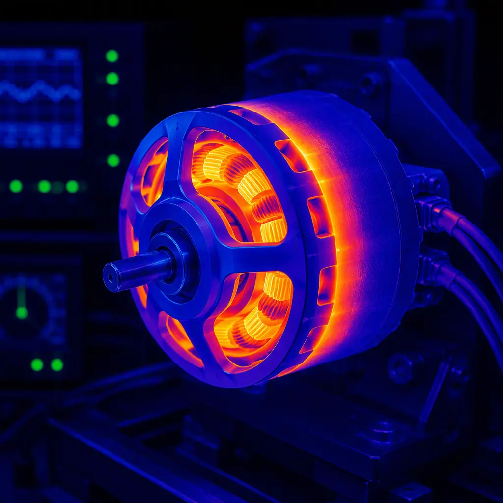
Winding and resistance. Copper fill factor: ≥ 65% (machine-wound) or ≥ 55% (hand-wound). Phase-to-phase resistance at 20°C: ≤ 0.15 Ω for a 300–500 KV motor with a 40–50 mm stator (higher resistance increases I²R loss and reduces efficiency at high current). Winding temperature class: Class H (180°C) minimum — this is the temperature at which the insulation system has a 20,000-hour life expectancy; Class F (155°C) is acceptable for motors that are not expected to operate above 130°C winding temperature. The supplier must provide a thermal test report showing the winding temperature at the rated continuous current after 30 minutes of operation in 25°C ambient air with no forced cooling — the test simulates the worst-case hover condition where the propeller downwash is the only cooling airflow, and the temperature must stabilise below the winding temperature class minus a 20°C safety margin.
 Concept illustration
Efficiency. The supplier must provide an efficiency map (efficiency vs torque vs RPM, or efficiency vs throttle percentage at the nominal battery voltage with a specified propeller load) measured on a dynamometer. The efficiency at 40% of the maximum rated torque (the hover condition for a UAV with 2.5:1 thrust-to-weight ratio) must be ≥ 80% for a motor in the 200–600 KV range. The peak efficiency (at 60–80% of maximum torque) must be ≥ 85%. The difference between the peak efficiency and the 40% torque efficiency — the partial-load efficiency penalty — must be ≤ 10 percentage points; a larger penalty indicates that the iron losses (which are load-independent) are disproportionately high, suggesting that the stator lamination material or thickness is inadequate.
Mechanical and environmental. Bearings: 2× deep-groove ball bearings, ABEC-5 or ABEC-7, with metal shields (ZZ) or rubber contact seals (2RS) for dust/water resistance. Shaft: hardened steel (HRC 55–60 minimum), 4–6 mm diameter for 35–50 mm stator motors, 8–12 mm for 80–100 mm stator motors — the shaft diameter must be verified with a bending stress calculation at the maximum rated thrust (the shaft is loaded in bending by the propeller thrust, and the bending stress at the bearing support must be below 50% of the shaft material's fatigue limit). Weight: the supplier's claimed weight must be verified on a calibrated scale by the procurement engineer — a motor that weighs 15% more than claimed has 15% less payload capacity for the same all-up weight, and a procurement engineer who does not weigh the motor before integrating it into the airframe is accepting a 15% payload penalty without knowing it.
Acceptance test. The supplier must provide the results of a 60-minute endurance test at the motor's rated continuous current with the intended propeller. The winding temperature must be recorded at 1-minute intervals (thermocouple embedded in the winding, not on the stator surface — the surface temperature is 10–20°C lower than the winding hot-spot temperature). The phase-to-phase resistance must be measured at 20°C before and after the test — a resistance increase of more than 5% indicates that the winding insulation is degrading under thermal stress, and the motor is not suitable for sustained operation at the rated continuous current. The magnet strength must be verified (back-EMF constant measurement at 1,000 RPM) before and after the test — a reduction of more than 2% indicates partial demagnetisation, and the magnet grade is inadequate for the operating temperature.
For the propulsion testing and validation procedures that verify the complete motor-propeller-ESC system performance — including the thrust stand measurement protocol, the thermal validation methodology and the endurance test criteria — the UAV propulsion testing and validation guide covers the end-to-end acceptance testing process. For the heavy-lift propulsion design considerations — including the motor sizing for platforms above 10 kg payload, the thermal management of 6–12 kW propulsion systems and the structural integration of large-diameter motors — the UAV heavy-lift propulsion design guide covers the scaling principles.
Matching motor topology to mission profile: a decision matrix
The following decision matrix summarises the motor topology selection for the seven most common industrial UAV mission profiles. The recommendation is based on the dominant operating condition — hover (multirotor), cruise (fixed-wing) or mixed (VTOL) — and the payload's vibration sensitivity.
| Mission Profile | Topology | Slot/Pole | Magnet | Drive |
|---|---|---|---|---|
| Survey & Photogrammetry (vibration-critical payload) | PMSM | 18N24P | N48SH | FOC |
| Precision Agriculture (spraying, non-vibration-critical) | BLDC | 12N14P | N42SH | Six-step or FOC |
| Heavy-Lift Logistics (8–25 kg payload) | BLDC or PMSM | 24N28P | N48SH | FOC recommended |
| Industrial Inspection (confined-space, FPV) | BLDC | 12N14P | N42SH | Six-step |
| Fixed-Wing Mapping (constant-RPM cruise) | PMAC (if available) or PMSM | 18N24P or 24N28P | N48SH | FOC |
| VTOL Transition (hover + cruise) | PMSM | 18N24P (lift motors) / 12N14P (push motor) | N48SH | FOC (all motors) |
| Defense & Security (encrypted, GNSS-denied) | PMSM | 18N24P or 24N28P | N48EH (200°C) | FOC |
For the VTOL transition components that bridge hover and cruise propulsion — including the tilt mechanisms, the transition flight controller logic and the dual-mode propulsion architecture — the UAV VTOL transition components guide covers the airframe-level integration decisions. For the defense and security application where the motor's acoustic signature, thermal signature and electromagnetic emissions are procurement-critical parameters — the defense and security UAV components guide covers the MIL-STD hardware requirements.
Selecting a motor topology is an electromagnetic decision that determines flight endurance — we will specify the right motor for your mission.
Explore custom engineering Back to Blog
Continue Reading
UAV Powertrain Matching
How to match the flight controller, ESC, motor and propeller into a coherent propulsion system — the system-level architecture that determines whether the motor's efficiency map is actually usable in flight.
UAV Motor KV Selection Guide
RPM-per-volt fundamentals, stator size vs KV trade-offs, thrust calculation methodology and propeller matching — the electrical parameters that determine the motor's operating point.

ESC Firmware Selection Guide
BLHeli_32, AM32 and FOC drive strategies — how the ESC's commutation algorithm interacts with the motor's back-EMF waveform to determine torque ripple and efficiency.
UAV Propeller Selection Guide
Diameter, pitch and blade count — the aerodynamic load that determines the motor's torque, RPM and position on the efficiency map at every flight condition.
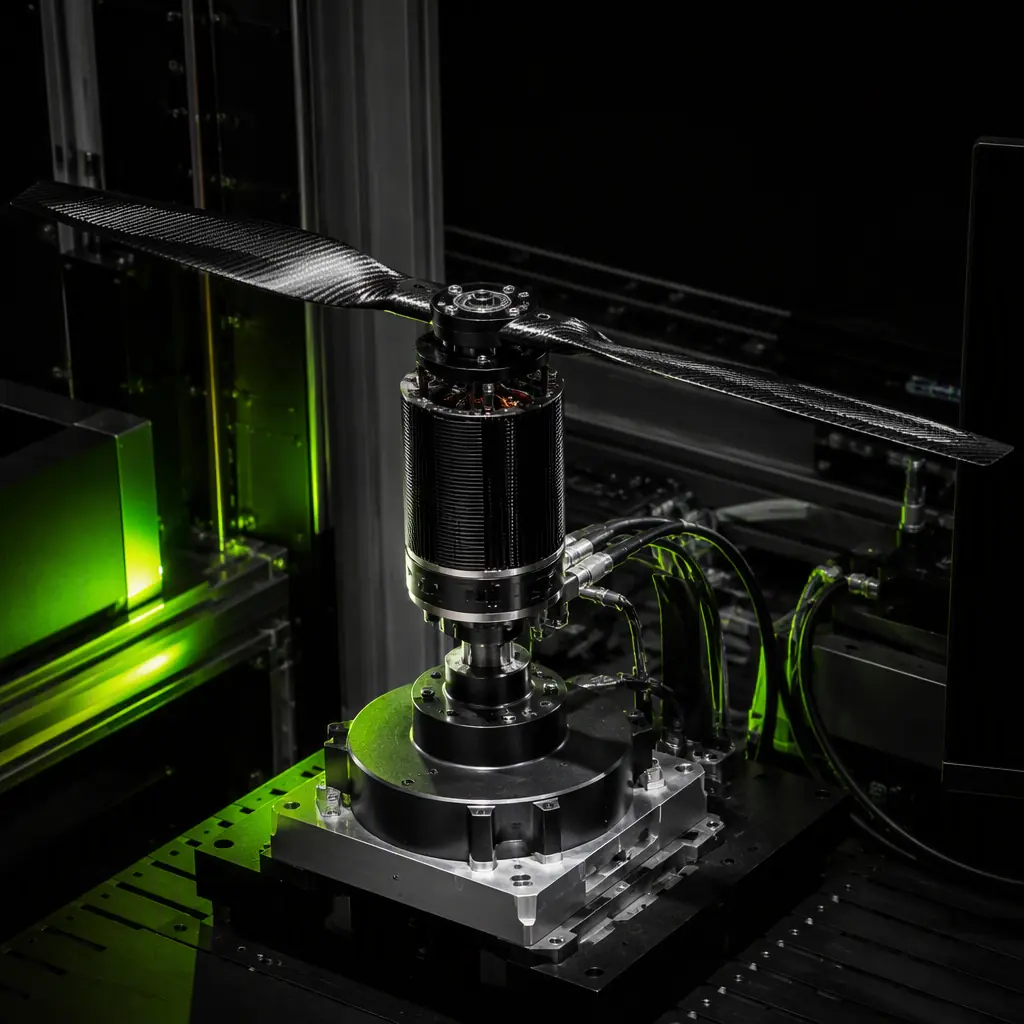
UAV Propulsion Testing & Validation
Thrust stand measurement protocol, thermal validation methodology and endurance test criteria — the acceptance testing that verifies the motor meets its procurement specification.