The difference between a 5 kg payload multicopter and a 50 kg payload heavy-lift platform is not linear. A drone carrying 10× the payload does not need 10× the motor power — it needs a propulsion architecture designed around fundamentally different physical constraints. Motor KV drops from the 400–600 range into the 100–200 range. ESC continuous current ratings move from 20–30 A to 60–100 A. Battery voltage climbs from 6S to 12S or 14S to keep current manageable at the higher power levels. Propeller diameter increases from 15–18 inches to 28–34 inches, and the aerodynamic regime shifts from predominantly inertial to Reynolds-number-sensitive flow where small changes in blade geometry produce large changes in thrust efficiency.
Procurement teams approaching heavy-lift propulsion for the first time often make the same mistake: they select the largest motor in a supplier's catalog and pair it with the largest propeller that physically fits, without validating whether the motor's torque constant, the ESC's commutation scheme and the propeller's thrust curve are matched at the operating point that matters — sustained hover at 50–60% throttle with the full payload mass. A 100 KV motor spinning a 32-inch propeller on 12S draws approximately 25 A at 50% throttle in static conditions. At 14S, the same throttle position on the same propeller draws 35 A — a 40% increase that may push the ESC beyond its continuous thermal rating. Getting these numbers right before procurement avoids the most expensive kind of discovery: finding the mismatch during payload integration testing.
The broader context for heavy-lift design decisions — including make-versus-buy trade-offs at the subsystem level — is covered in the build vs buy sourcing framework. The propulsion decisions here assume you have committed to purchasing matched motor/ESC/propeller sets and are now selecting the specifications.
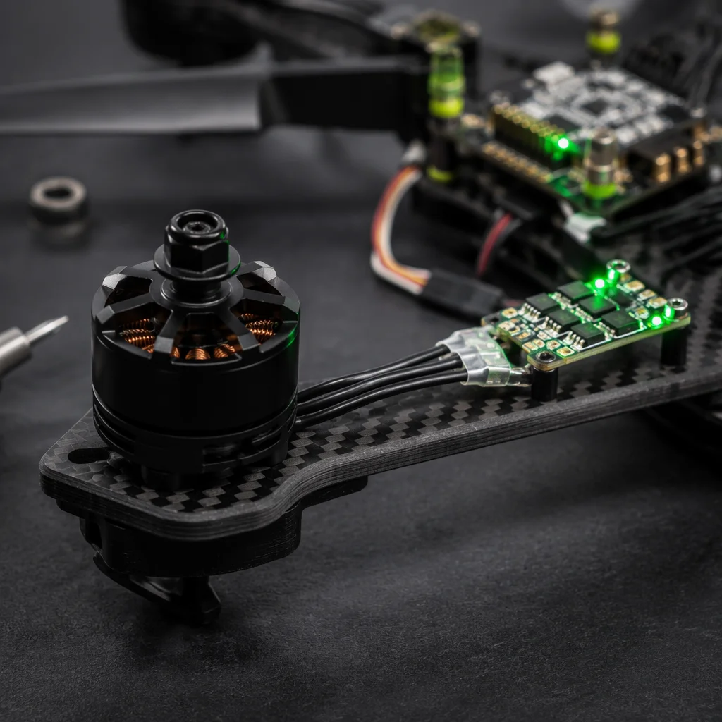
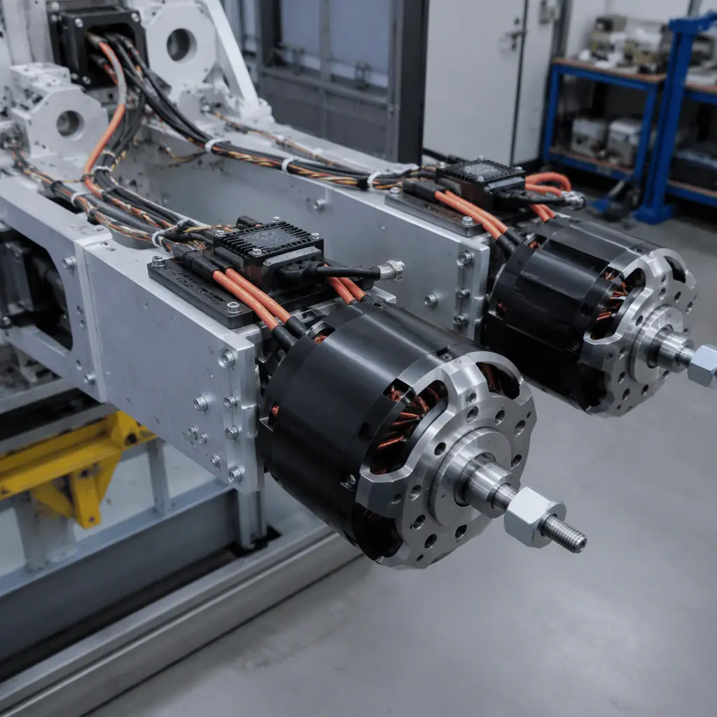 Heavy-lift motor and ESC assembly
Motor selection: KV, torque constant and thermal envelope for sustained hover
Motor KV — RPM per volt with no load — is the first-order selection parameter for heavy-lift propulsion, but it must be understood in the context of the complete electromechanical system. A 100 KV motor on 12S (44.4 V nominal) has a no-load speed of 4,440 RPM. Under load at 50% throttle with a 32-inch propeller, actual RPM drops to approximately 2,200–2,600 RPM depending on propeller pitch and blade count. The difference between no-load and loaded RPM is proportional to the motor's winding resistance and the torque demand of the propeller — and it is this difference, not the no-load KV, that determines whether the motor is correctly sized for the application.
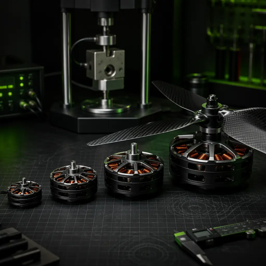
For heavy-lift platforms in the 10–50 kg payload class, target motors in the 100–200 KV range with stator dimensions of 80–100 mm diameter and 20–30 mm height. These motors typically weigh 500–1,200 g each and produce 8–15 kg of thrust per motor with 28–34 inch propellers on 12S–14S. The winding should be specified for Class H insulation (180°C rated) or higher; under sustained hover with 25–35 A continuous current, winding temperature stabilizes at 110–140°C in 25°C ambient — well within Class H limits but approaching the failure point for Class B (130°C) windings that some lighter-duty motors use.
The torque constant Kt (N·m/A) is the companion specification to KV: Kt = 60 / (2π × KV) for units in N·m/A. A 150 KV motor has Kt ≈ 0.064 N·m/A. At 30 A continuous, the motor produces 1.91 N·m of torque. The propeller's torque demand at the target RPM must be below this value with at least 20% margin for control authority during gusts and maneuvers. If the propeller demands 2.0 N·m at the target hover RPM and the motor can only deliver 1.91 N·m, the system will settle at a lower RPM than intended — producing less thrust and forcing the flight controller to command higher throttle on all motors, reducing the available headroom for attitude control. The detailed approach for matching motor constants to propeller load curves is described in the UAV powertrain matching guide.
ESC selection: CAN FD, DShot 1200 and thermal management at 40–80 A
Heavy-lift ESCs operate in a regime where the commutation scheme matters as much as the current rating. A 60 A continuous-rated ESC running a 150 KV motor with a 32-inch propeller at 50% throttle sees average currents of 25–35 A but peak phase currents during commutation that can exceed 80 A for tens of microseconds. If the ESC's MOSFET gate drivers cannot handle these transients without voltage overshoot, the result is cumulative damage to the FET body diodes — not immediate failure, but a slowly increasing RDS(on) that raises conduction losses, increases thermal load, and eventually causes a thermal shutdown mid-flight after 30–50 flight hours.
For heavy-lift applications, specify ESCs with the following minimum requirements: continuous current rating of 60–100 A (not burst rating — verify the test conditions behind the continuous rating), CAN FD bus interface for real-time telemetry at 5–8 Mbps with per-phase current sensing, and DShot 1200 for the primary throttle signal with a fallback to PWM at 400 Hz. The CAN FD telemetry channel is not optional for heavy-lift — it provides per-motor current, voltage, temperature and RPM data at 50–100 Hz, which the flight controller or companion computer uses to detect a motor that is drawing 15% more current than its matched pair, indicating a bearing degradation or propeller imbalance before it becomes a flight-critical failure.
The ESC firmware selection guide covers BLHeli_32 versus AM32 versus FOC firmware trade-offs in detail. For heavy-lift, the key firmware consideration is low-speed control quality: FOC (field-oriented control) provides smoother torque delivery at the 5–15% throttle range used during descent and landing, where a trapezoidal-commutation ESC can produce audible cogging and thrust pulsation that interferes with precision landing sensors. If your heavy-lift platform performs autonomous precision landings on a 1-meter pad, FOC is worth the cost premium over BLHeli_32. If it lands on open ground with a 3-meter tolerance, BLHeli_32 at DShot 1200 is sufficient.
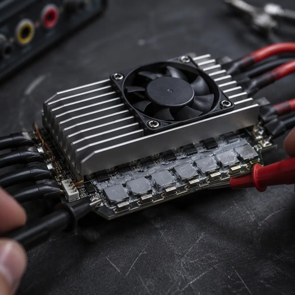 Heavy-lift ESC thermal design
Propeller selection: diameter, pitch and the static thrust efficiency curve
For heavy-lift UAVs designed to hover with significant payload — logistics delivery platforms, agricultural sprayers with 20–40 L tanks, and sensor pods weighing 15–30 kg — propeller selection optimizes for static thrust efficiency, not forward-flight efficiency. The figure of merit is grams of thrust per watt of electrical power at the target hover throttle position, typically 50–60%.
Large-diameter, low-pitch propellers maximize static thrust efficiency. A 32×10-inch propeller (32-inch diameter, 10-inch pitch — advancing 10 inches per revolution in an ideal fluid) at 2,400 RPM on a 150 KV motor produces approximately 11–13 kg of static thrust while consuming 800–1,000 W. The same motor with a 30×12-inch propeller at the same RPM produces 9–10 kg of thrust at similar power — the smaller diameter disc accelerates a smaller air mass, which is inherently less efficient for static thrust. But the 30×12 propeller performs better in forward flight above 15 m/s because the higher pitch maintains thrust as the incoming air velocity reduces the effective angle of attack on the blade. For a platform that spends 90% of its flight time in hover — which describes most heavy-lift logistics and agricultural UAVs — the larger diameter, lower pitch propeller is the correct choice.
For coaxial configurations — two motors stacked on the same arm, one pushing and one pulling — the lower propeller operates in the accelerated slipstream of the upper propeller and requires approximately 10–15% more pitch to maintain the same thrust at the same RPM. A coaxial pair with 32×10 on top and 32×12 on bottom produces balanced thrust at the same motor RPM. For X8 (coaxial octocopter) configurations targeting 50 kg payload, the coaxial efficiency penalty (typically 15–20% less total thrust than eight isolated motors on eight arms) must be factored into the total thrust budget. The UAV propeller selection guide provides the broader framework for matching propeller geometry to mission profiles, including the static-versus-dynamic efficiency trade-off.
Battery architecture: 12S–14S Li-Ion packs for energy density
Heavy-lift UAVs draw 4–8 kW in hover. At 6S (22.2 V nominal), 8 kW requires 360 A total system current — which demands bus bars, connectors and wiring that add kilograms of copper to the airframe. At 12S (44.4 V), the same 8 kW draws 180 A. At 14S (51.8 V), it draws 154 A. Each step up in voltage reduces current proportionally, which reduces I²R losses in wiring and connectors and allows the use of lighter-gauge wiring — but it also requires ESCs and power distribution boards rated for the higher voltage, and these components are less common and more expensive above 12S.
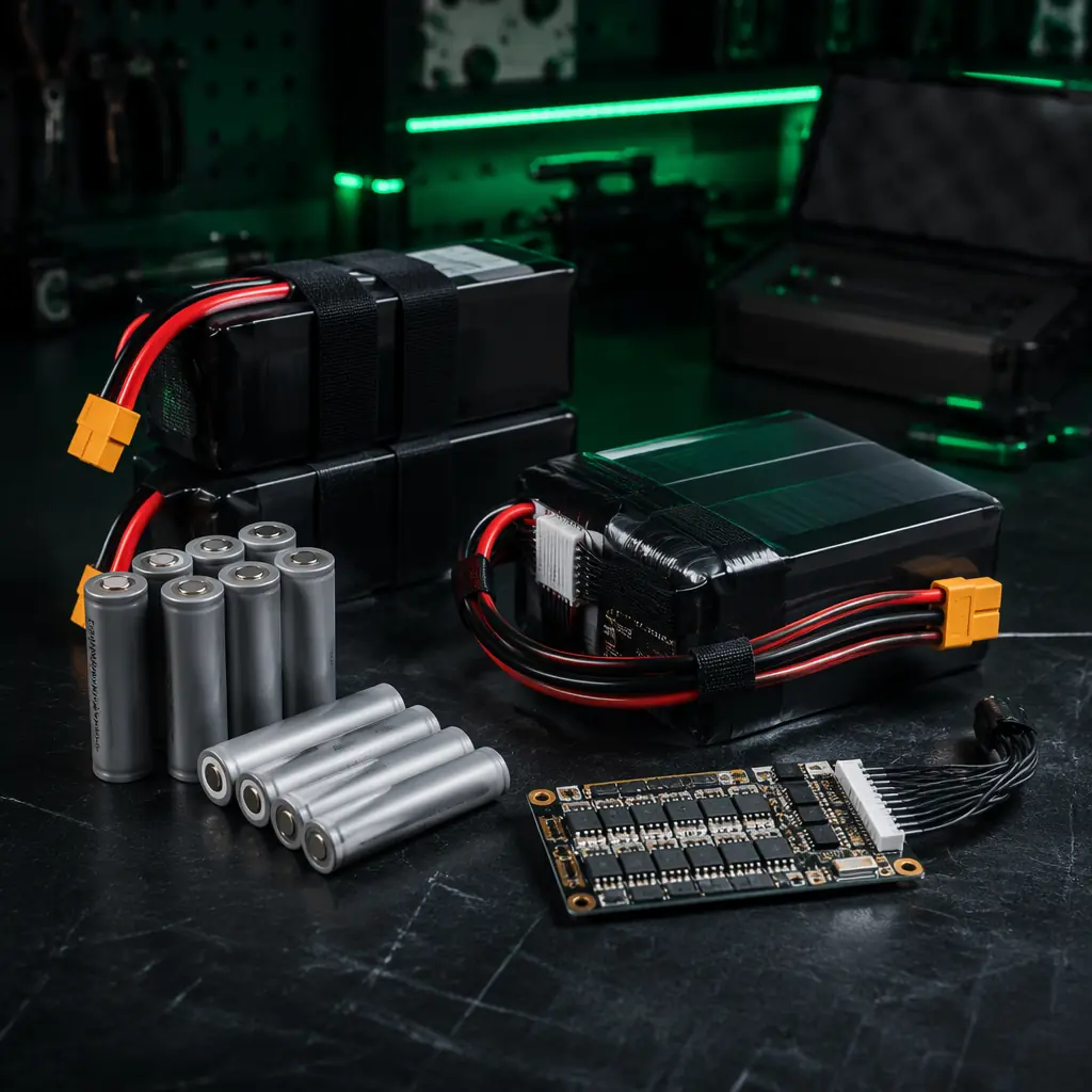
The standard configuration for the 10–50 kg payload class is 12S Li-Ion (not LiPo) with 6S–12S modules in series-parallel arrangements. Li-Ion cells (Samsung 50S, Molicel P42A, or Sony VTC6 in 21700 format) deliver 150–250 Wh/kg compared to 120–160 Wh/kg for equivalent LiPo packs. For a 30-minute hover mission at 6 kW average power, the weight difference between Li-Ion (3.0 kWh required ÷ 200 Wh/kg = 15 kg pack) and LiPo (3.0 kWh ÷ 140 Wh/kg = 21.4 kg pack) is 6.4 kg — which is payload capacity that could instead be used for sensors, a delivery package, or additional endurance.
The trade-off is discharge rate: Li-Ion cells rated for 10–15 A continuous per cell can deliver 20–30 A in burst but will sag more under load than LiPo cells rated for 30–50 C. For heavy-lift platforms operating at 50–60% throttle in steady hover, the continuous discharge rate is the binding constraint, and Li-Ion's energy density advantage wins. For platforms that require frequent full-power climbs — such as a delivery drone ascending 200 meters vertically with a full payload in under 60 seconds — the burst current demand may push Li-Ion cells into voltage sag that triggers the flight controller's low-battery failsafe. In this scenario, a hybrid approach using LiPo for the climb phase and Li-Ion for cruise provides the best of both chemistries, but adds pack-switching complexity. For a deeper treatment of battery selection across the full UAV power spectrum, see UAV battery and power management.
Redundancy architectures for heavy-lift propulsion
A 50 kg payload UAV hovering at 100 meters altitude has no safe failure mode if a single motor, ESC or propeller fails without redundancy. The standard redundancy architectures for heavy-lift are:
X8 coaxial octocopter. Eight motors on four arms, each arm carrying a coaxial pair. A single motor or ESC failure on one arm leaves the other motor on that arm producing reduced but non-zero thrust, and the remaining six motors can maintain controlled flight — though not hover — long enough for a controlled descent. This is the most common architecture for logistics and agricultural heavy-lift because it provides motor-level redundancy in a compact footprint. The coaxial penalty reduces total thrust efficiency by 15–20% relative to a flat octocopter, but the packaging advantage (four arms instead of eight) usually outweighs the efficiency loss for ground-transportable platforms.
Hexacopter with 50% thrust margin. Six motors sized so that any five can maintain hover at ≤80% throttle with full payload. This requires each motor to produce 120% of its 1/N share of total thrust — a six-motor platform needs each motor capable of 20% of total thrust rather than 16.7%, a 20% oversize penalty. This approach is simpler than coaxial (single motors, single ESCs per arm) but offers less redundancy margin: if a second motor fails before landing, the remaining four cannot maintain altitude. For platforms operating over water or populated areas, X8 coaxial is the safer choice despite the efficiency penalty.
Dual independent battery buses. Two separate battery packs, each powering half the motors through independent power distribution boards. A single battery failure — a cell going open-circuit, a connector melting, a BMS triggering a protective shutdown — affects only half the propulsion system. The remaining half can maintain controlled descent. This adds approximately 5–8% weight overhead for the second PDB and additional wiring, but for platforms carrying payloads valued at $50,000 or more (survey LiDAR, broadcast cameras, medical delivery payloads), the weight penalty is negligible compared to the cost of a total loss.
For platforms operating in the low-altitude economy — particularly urban logistics and medical delivery — redundancy is not just an engineering decision but increasingly a regulatory requirement. EASA's SORA (Specific Operations Risk Assessment) methodology and FAA's proposed BVLOS rule both treat propulsion redundancy as a primary mitigator for the ground risk class, and a platform without motor-level redundancy may be restricted to operations over unpopulated areas regardless of other safety features.
Thermal management: keeping 4–8 kW of propulsion within operating limits
A heavy-lift octocopter consuming 6 kW in hover dissipates approximately 600–900 W as heat across eight motors and eight ESCs — roughly 40–55 W per motor and 30–50 W per ESC. This is not a trivial thermal load. A motor winding at 140°C transfers heat to the stator, which transfers heat to the motor mount, which transfers heat to the carbon fiber or aluminum arm. If the arm's epoxy resin has a glass transition temperature (Tg) of 80–120°C — typical for medium-temperature carbon fiber laminates — sustained operation with motor mounts above 100°C can soften the arm structure at the mounting point, causing progressive loosening of motor bolts and eventual structural failure at the motor-arm interface.
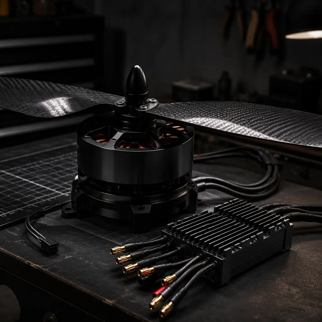
The mitigation strategy has three layers. First, specify motors with integrated centrifugal fans — most motors in the 80–100 mm stator class include a fan machined into the rotor bell that pulls air through the windings at 2,000–4,000 RPM. Verify that the fan is effective at the target hover RPM, not just at full throttle; a fan designed for 6,000 RPM cruise may produce negligible airflow at 2,400 RPM hover. Second, use aluminum motor mounts with thermal paste at the motor-mount interface to conduct heat into the arm structure before it concentrates at the mounting bolts. Third, for ESC thermal management, mount ESCs in the propeller downwash with finned heatsinks oriented parallel to the airflow direction. An ESC dissipating 40 W in still air reaches 120°C junction temperature within 5 minutes; the same ESC in 8 m/s propeller downwash stabilizes at 65–75°C — still warm, but 50°C below the typical 125°C MOSFET junction temperature limit.
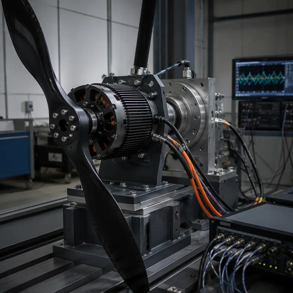 Propulsion system validation
Procurement checklist: specifying a heavy-lift propulsion stack
When issuing an RFQ for heavy-lift propulsion components, the following specification points separate a well-defined requirement from a vague request that will produce mismatched quotes:
1. Total thrust requirement with margin. Specify the all-up weight (AUW) including payload, and the required thrust-to-weight ratio at hover throttle. Standard: 2.0:1 for multicopters (total system thrust ≥ 2× AUW), 1.8:1 for coaxial X8 (accounting for coaxial loss), and 1.5:1 for fixed-wing VTOL in hover mode. Include the altitude and temperature at which this thrust must be available — a 2.0:1 ratio at sea level and 25°C becomes 1.5:1 at 2,500 m density altitude and 40°C.
2. Motor KV and winding temperature class. Specify KV range (100–200 for 12S, 80–150 for 14S), stator dimensions, and minimum winding temperature class (Class H / 180°C). Request the motor's efficiency map across the 30–100% throttle range with the intended propeller — not just the peak efficiency point at 80% throttle, which is not where the motor operates in hover.
3. ESC protocol and telemetry requirements. Specify DShot 1200 as primary protocol, CAN FD at 5–8 Mbps for telemetry, and the telemetry data fields required: per-phase current, DC bus voltage, MOSFET temperature, commutation frequency, and error flags. The telemetry interface is the basis for in-flight propulsion health monitoring; without it, a motor drawing 20% excess current due to bearing wear is undetectable until it seizes.
4. Propeller thrust curve data. Request static thrust (kgf) vs. RPM curves for the matched propeller at 100 RPM increments from 1,500–3,500 RPM, measured at the target operating altitude density. CFD simulations are acceptable for initial evaluation but must be validated with at least three measured data points before procurement commitment.
5. Battery continuous discharge validation. For Li-Ion packs, request a discharge curve at the expected continuous current (typically 0.5C–1C for heavy-lift) showing voltage vs. capacity from 4.2 V/cell to 3.0 V/cell. The voltage at 80% depth of discharge determines the usable flight time — a pack that sags to 3.2 V/cell at 60% DoD effectively delivers only 40% of its rated capacity at full power. The validation approach parallels the testing methodology in UAV propulsion testing and validation.
Explore propulsion capabilities Back to Blog