
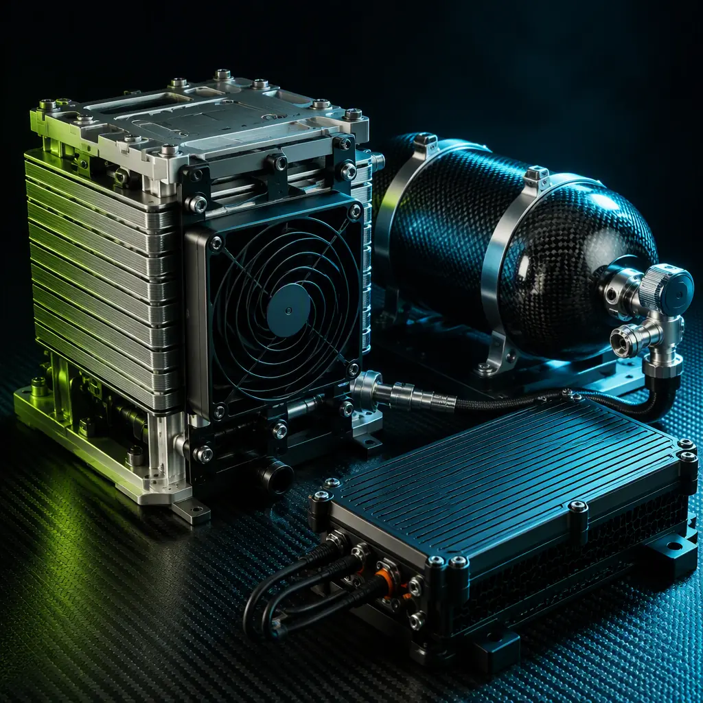
The fundamental limitation of battery-electric UAV propulsion is the specific energy of the energy storage medium. The best commercially available lithium-polymer cells — the LiPo packs that power the majority of professional multirotors and fixed-wing UAVs today — deliver 180–220 Wh/kg at the cell level and 150–180 Wh/kg at the pack level after accounting for the cell interconnects, the packaging, the battery management system (BMS) and the state-of-charge reserve that protects the pack from deep discharge damage. A 6S 22,000 mAh LiPo pack weighing 3.2 kg stores approximately 488 Wh of usable energy — enough to hover a 25 kg multirotor drawing 2.8–3.2 kW for approximately 9–10 minutes per pack, or approximately 35–45 minutes with four such packs in parallel (12.8 kg of batteries, representing 51% of the aircraft's all-up weight). The hydrogen fuel cell changes the arithmetic: compressed hydrogen at 350 bar stores 33.3 kWh of lower heating value (LHV) energy per kilogram of H₂ — approximately 120× the specific energy of the LiPo cell at the fuel level. The fuel cell stack converts that chemical energy to electrical energy at 45–55% system efficiency (DC net, after the stack, the air compressor, the cooling pump and the power conditioning), yielding 400–600 Wh of usable DC electricity per kilogram of system weight including the stack, the balance of plant and the hydrogen storage — a factor of 2.2–3.3× improvement over the battery pack. For the procurement team evaluating a hydrogen fuel cell for a UAV programme, this article translates the electrochemical advantage into a component specification document.
The endurance equation: battery, hydrogen and the crossover point
The procurement decision between battery-electric and fuel-cell-electric propulsion reduces to a single question: at what flight endurance does the hydrogen system's higher system-level specific energy overcome its higher system-level specific power penalty? A battery pack's specific power — the rate at which it can deliver energy per unit mass — is typically 2,000–4,000 W/kg for a high-discharge LiPo (the Turnigy Graphene Panther 6S 75C pack delivers approximately 3,500 W/kg at the burst rating). A PEM fuel cell stack's specific power is 500–1,500 W/kg for current-generation air-cooled open-cathode stacks (the Intelligent Energy 650 W stack module weighs 1.2 kg including the integrated cooling fan, delivering 540 W/kg; the 2.4 kW version weighs 3.2 kg for 750 W/kg). The fuel cell's lower specific power means that for a given power requirement — the hover power of the multirotor, or the cruise power of the fixed-wing — the fuel cell system is heavier than a battery system of equivalent power output. But the fuel cell's higher specific energy means that the fuel cell system's weight grows more slowly as the endurance requirement increases: the battery system's weight is linear with endurance (double the endurance = double the battery mass), while the fuel cell system's weight grows only with the hydrogen fuel mass (double the endurance = double the fuel, but the stack and balance-of-plant mass are fixed). The crossover point — the endurance at which the fuel cell system becomes lighter than the battery system for the same mission energy requirement — is determined by the ratio of the two systems' specific energy and specific power.
Define the system masses: for a battery system, m_batt = P_cruise / ρ_batt + E_mission / ε_batt, where P_cruise is the cruise power (watts), ρ_batt is the battery's specific power (W/kg), E_mission is the mission energy requirement (watt-hours) and ε_batt is the battery pack's usable specific energy (Wh/kg). For the hydrogen system, m_h2 = P_cruise / ρ_stack + E_mission / ε_h2 + m_BOP, where ρ_stack is the fuel cell stack's specific power (W/kg), ε_h2 is the system-level specific energy including the hydrogen storage mass (Wh/kg) and m_BOP is the fixed balance-of-plant mass (air compressor, humidifier, coolant pump, power management unit — typically 0.8–2.0 kg for a 500 W–3 kW system). Setting m_batt = m_h2 and solving for E_mission yields the crossover energy:
E_crossover = (P_cruise × (1/ρ_batt − 1/ρ_stack) + m_BOP) / (1/ε_h2 − 1/ε_batt). For a representative fixed-wing UAV cruising at 600 W with a battery pack delivering 180 Wh/kg at 3,000 W/kg, a fuel cell stack delivering 600 Wh/kg (system level, including the 350 bar compressed hydrogen cylinder at 5.7 wt% storage efficiency) at 750 W/kg, and a BOP mass of 1.5 kg: the numerator = 600 × (1/3,000 − 1/750) + 1.5 = 600 × (0.000333 − 0.001333) + 1.5 = 600 × (−0.001) + 1.5 = −0.6 + 1.5 = 0.9. The denominator = (1/600 − 1/180) = 0.001667 − 0.005556 = −0.003889. The crossover energy E_crossover = 0.9 / 0.003889 = 231 Wh. A 600 W cruise power drawing 231 Wh of energy corresponds to 231 / 600 = 0.385 hours = 23 minutes of flight. For any mission exceeding 23 minutes, the hydrogen system is lighter than the battery system — and the weight advantage grows with endurance: at 2 hours of cruise (1,200 Wh), the battery system weighs 600/3,000 + 1,200/180 = 0.2 + 6.7 = 6.9 kg, while the hydrogen system weighs 600/750 + 1,200/600 + 1.5 = 0.8 + 2.0 + 1.5 = 4.3 kg — a 38% weight reduction. At 4 hours (2,400 Wh), the battery system weighs 0.2 + 13.3 = 13.5 kg and the hydrogen system weighs 0.8 + 4.0 + 1.5 = 6.3 kg — a 53% reduction. The crossover point calculation is the first step in the procurement analysis: if the mission endurance requirement is below the crossover point, a battery system is the lighter and simpler option. If it is above, the hydrogen system's weight advantage justifies the additional complexity of the fuel handling, the certification and the ground support infrastructure.
For multirotor platforms, the crossover point shifts to shorter endurances because the power requirement is higher — a 25 kg multirotor hovering at 2.8 kW has a crossover at approximately 15–18 minutes, meaning that any multirotor mission exceeding 20 minutes of hover benefits from hydrogen. For the battery sizing methodology that provides the baseline against which the fuel cell system is compared, the UAV battery power management guide covers the LiPo and Li-Ion pack sizing, the BMS selection and the charging infrastructure decisions that inform the battery side of the trade study.
 Concept illustration
PEM fuel cell stack selection: power, voltage and the propulsion bus interface
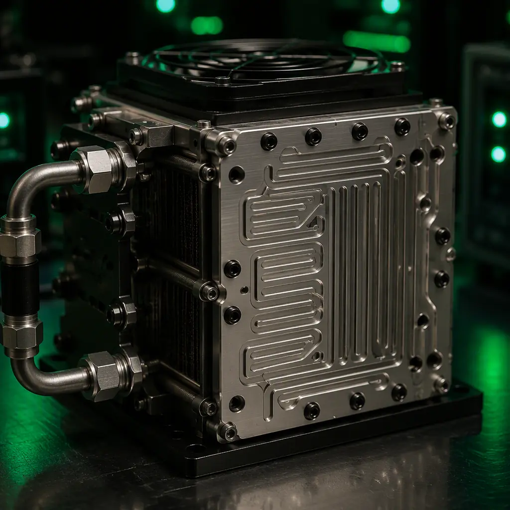
The proton-exchange membrane (PEM) fuel cell is the dominant architecture for UAV propulsion because it operates at 60–80°C — low enough for a lightweight air-cooled thermal management system, high enough for efficient electrochemical kinetics without requiring the precious-metal catalyst loadings that make low-temperature alkaline fuel cells prohibitively expensive. The PEM stack's output is low-voltage DC: a single cell produces 0.6–0.7 V at the operating current density (typically 0.4–0.8 A/cm² for a UAV stack optimized for efficiency over power density), so a stack of 40–60 cells in series produces 24–42 V DC — compatible with the 6S (22.2 V nominal) to 14S (51.8 V nominal) propulsion bus voltages used in professional UAVs. The procurement specification for the PEM stack must define five parameters: the rated power, the voltage range, the current range, the efficiency curve and the startup time.
Rated power. The stack's continuous rated power must equal or exceed the UAV's cruise power plus the avionics load with a 20% margin for headwinds, altitude derating and battery charging (if the architecture includes a hybrid buffer battery). The cruise power of a fixed-wing UAV at the best lift-to-drag (L/D) airspeed is P_cruise = (m × g / (L/D)) × v_cruise / η_prop, where m is the aircraft mass (kg), g = 9.81 m/s², L/D is the lift-to-drag ratio (typically 8–15 for a small fixed-wing UAV, 3–5 for a multirotor in forward flight) and η_prop is the propulsion system efficiency from the electrical input to the propeller shaft output (typically 0.65–0.80 for a brushless motor + ESC + propeller combination at the cruise operating point). For a 25 kg fixed-wing UAV with L/D = 10, v_cruise = 20 m/s (72 km/h) and η_prop = 0.75: P_cruise = (25 × 9.81 / 10) × 20 / 0.75 = 24.5 × 20 / 0.75 = 654 W. Adding 30 W for the avionics (flight controller at 5 W, GPS at 2 W, telemetry radio at 5 W in receive mode, companion computer at 10 W, and camera payload at 8 W) and applying the 20% margin: P_rated = (654 + 30) × 1.2 = 821 W. The procurement team should specify an 850 W or 1,000 W rated stack for this airframe — the 650 W stack is undersized, and a headwind of 5 m/s (increasing the airspeed requirement from 20 to 25 m/s for the same groundspeed) would increase the cruise power to P = (25 × 9.81 / 10) × 25 / 0.75 = 818 W, leaving no margin for the avionics or the battery charging load.
Voltage range. The stack's voltage under load follows the polarization curve: at open circuit (no current draw), each cell produces approximately 0.95–1.0 V; at the rated current density of 0.6 A/cm², each cell drops to 0.65–0.70 V due to the activation overpotential (the energy required to initiate the electrochemical reaction at the catalyst surface, dominant at low current densities), the ohmic overpotential (the voltage drop across the membrane's proton resistance and the bipolar plate's electrical resistance, dominant at medium current densities) and the concentration overpotential (the voltage drop due to reactant depletion at the catalyst surface, dominant at high current densities where the hydrogen and oxygen cannot diffuse through the gas diffusion layer fast enough to replenish the reaction sites). A 50-cell stack at open circuit produces 47.5–50 V; at the rated power of 850 W and 0.65 V/cell, the stack produces 32.5 V at 26.2 A. The procurement specification must define the voltage range that the propulsion bus power management unit (PMU) must accept: typically 24–50 V DC input, with the PMU's DC-DC converter boosting or bucking the stack voltage to the propulsion bus voltage (44.4 V for a 12S LiPo bus, 51.8 V for a 14S bus). The PMU's efficiency across the 24–50 V input range should be ≥ 94% to avoid wasting 50–100 W of the stack's output as heat in the converter — a 50 W loss in a 850 W system is 5.9%, acceptable only if the PMU's heat sink can dissipate 50 W in the avionics bay airflow. For the ESC and power bus architecture that receives the PMU's output, the UAV heavy-lift propulsion design guide covers the power distribution and redundancy architecture.
Efficiency curve. The stack's efficiency — the ratio of DC electrical power output to the hydrogen's lower heating value (LHV) energy input — is a function of the operating point. At the rated power of 850 W and 0.65 V/cell, the stack efficiency is η_stack = (V_cell × n_cells) / (n_cells × 1.254 V) = V_cell / 1.254 = 0.65 / 1.254 = 51.8%, where 1.254 V is the thermoneutral voltage of the hydrogen-oxygen reaction (the voltage at which the electrical energy output equals the reaction's enthalpy change — at voltages below 1.254 V, the excess enthalpy is released as heat). At 50% of rated power (425 W), the cell voltage increases to approximately 0.72 V (lower current density → lower overpotential → higher cell voltage), and the efficiency increases to 0.72 / 1.254 = 57.4% — but the stack's fixed parasitic loads (the air compressor, the cooling fan, the control electronics) consume a constant 20–40 W regardless of the output power, reducing the net system efficiency at part load. The procurement team should request the supplier's efficiency map — a plot of system efficiency (DC output net of parasitics divided by hydrogen LHV input) versus output power from 10% to 100% of rated power — and verify that the efficiency at the cruise power operating point (not the rated power) is ≥ 48% system-level. A system that achieves 55% peak efficiency at 60% rated power but drops to 42% at the cruise power is wasting 8–10% of the hydrogen fuel as heat that must be rejected through the air-cooled stack housing — and at 3–5 hours of flight, that wasted energy represents 300–500 Wh of additional hydrogen that must be carried, increasing the fuel mass by 90–150 grams of compressed H₂ (at 33.3 kWh/kg LHV) and the cylinder mass by 300–500 grams (at 5.7 wt% storage efficiency for a Type 3 aluminum-lined carbon-fiber-overwrapped cylinder at 350 bar).
Startup time. The PEM stack requires 30–120 seconds from the hydrogen valve opening to full rated power: the membrane must hydrate (the proton conductivity of a Nafion membrane increases by three orders of magnitude from the dry state — 0.001 S/cm — to the fully hydrated state — 0.1 S/cm — and hydration requires the water produced by the electrochemical reaction to diffuse through the membrane, a process that takes 20–60 seconds at the stack's operating temperature), the air compressor must spool up to the stoichiometric air flow rate (typically 2.0–2.5× the stoichiometric oxygen requirement, to ensure excess oxygen at the catalyst surface — insufficient air flow causes oxygen starvation, which permanently degrades the cathode catalyst through carbon corrosion at the catalyst support), and the power conditioning electronics must synchronize to the propulsion bus voltage. During the startup transient, the UAV's avionics and the propulsion system must be powered by the hybrid buffer battery — a 3S–6S LiPo pack of 2,000–5,000 mAh that supplies the 100–200 W of avionics load for 3–5 minutes of ground checkout and the first 2 minutes of flight while the fuel cell reaches full power. The procurement specification must state the maximum acceptable startup time from the hydrogen valve opening to 90% of rated power: 60 seconds for a multirotor that takes off vertically (the battery can power the takeoff, and the fuel cell can assume the propulsion load once the UAV is at altitude), or 120 seconds for a fixed-wing that can launch on battery power and transition to fuel cell power in cruise. For the hybrid architecture design that manages the startup transient and the peak power events, see Section 5 of this article.
 Concept illustration
Hydrogen storage: compressed gas, chemical hydrides and the weight trade-off
The hydrogen storage subsystem is the heaviest single component of the fuel cell power system — and the component whose technology choice most directly determines the system's specific energy. Three storage technologies are commercially available for UAV applications: compressed gaseous hydrogen (CGH₂) at 300–700 bar, chemical hydride cartridges that release hydrogen through a thermolysis or hydrolysis reaction, and liquid organic hydrogen carriers (LOHC) that bind hydrogen to a liquid organic molecule and release it through catalytic dehydrogenation. The procurement decision between them is driven by the mission endurance, the ground support infrastructure available at the operating location, and the regulatory acceptance of the storage technology for UAV operations in the target airspace.
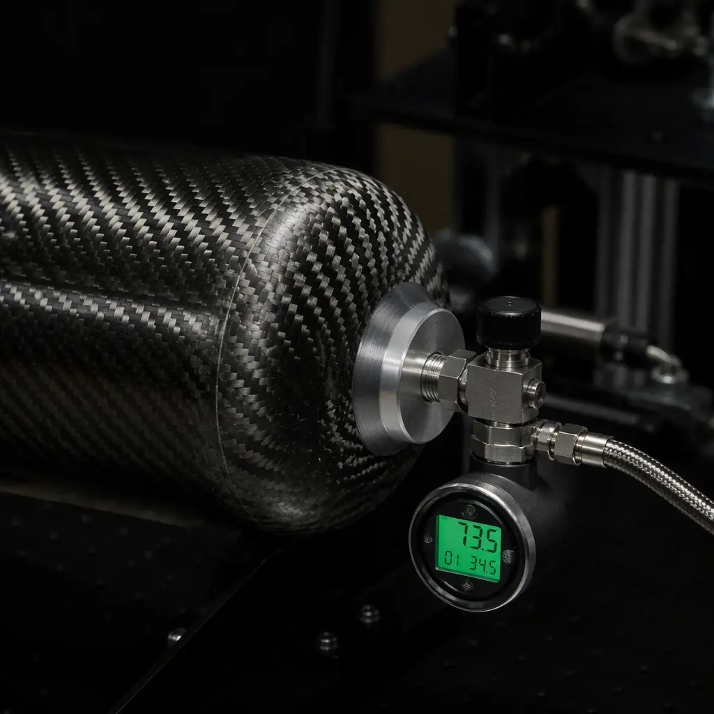
Compressed gaseous hydrogen at 350 bar. The Type 3 cylinder — an aluminum 6061-T6 liner overwrapped with T700 or T800 carbon fiber in an epoxy matrix — stores 1.5–3.0 kWh of usable electrical energy (after the stack's 50% conversion efficiency) per kilogram of cylinder mass, depending on the cylinder's diameter (smaller cylinders have a higher surface-to-volume ratio and therefore a higher liner-to-contents mass ratio, reducing the gravimetric storage efficiency). A 2.0 L water-volume cylinder at 350 bar and 15°C holds 2.0 × 350 / 1.01325 × 0.0899 / 1,000 × 296.25 / 288.15 = approximately 56 grams of H₂ (the ideal gas law corrected for the compressibility factor of hydrogen at 350 bar, Z ≈ 1.15 at 15°C, reducing the actual H₂ mass to 56 / 1.15 = 49 grams). At the LHV of 33.3 kWh/kg, 49 grams of H₂ contains 1.63 kWh of chemical energy; at 50% system conversion efficiency, the usable DC output is 815 Wh. The cylinder mass for a 2.0 L Type 3 cylinder rated at 350 bar is approximately 1.0–1.3 kg (the aluminum liner is 0.3–0.4 kg, the carbon fiber overwrap is 0.6–0.8 kg, and the boss, valve and pressure regulator add 0.1–0.2 kg), yielding a storage efficiency of 49 g H₂ / 1,200 g cylinder = 4.1 wt% — at the low end of the 4–6 wt% range for small Type 3 cylinders. The usable system-level specific energy including the cylinder, the pressure regulator and the connecting plumbing is ε_h2_storage = 815 Wh / 1.3 kg = 627 Wh/kg for the storage subsystem alone — higher than the 150–180 Wh/kg of the battery pack, but the stack and BOP reduce the full-system specific energy to 400–550 Wh/kg as calculated in Section 1.
Compressed hydrogen at 700 bar. The Type 4 cylinder — a polymer (HDPE or PA) liner overwrapped with carbon fiber — stores hydrogen at 700 bar, increasing the hydrogen density from 23.5 g/L at 350 bar to 39.5 g/L at 700 bar (at 15°C, corrected for the compressibility factor Z ≈ 1.35 at 700 bar). The same 2.0 L water volume holds 39.5 × 2.0 = 79 grams of H₂ — 61% more than at 350 bar — but the cylinder mass increases to 2.5–3.5 kg because the hoop stress in the carbon fiber overwrap is proportional to the pressure (700 bar vs 350 bar = 2× the hoop stress, requiring 2× the carbon fiber wall thickness), and the Type 4 liner provides no structural contribution (unlike the Type 3 aluminum liner, which carries approximately 15–20% of the hoop load). The storage efficiency for the 2.0 L Type 4 cylinder is 79 g / 3,000 g = 2.6 wt% — worse than the 350 bar Type 3 cylinder despite the higher hydrogen density, because the heavier cylinder more than offsets the additional fuel mass for small cylinders. The 700 bar cylinder becomes advantageous for larger UAVs with hydrogen capacities above 200–300 grams (10–15 kWh of DC output), where the cylinder mass scales more favourably: a 6.8 L water-volume Type 4 cylinder holding 268 g of H₂ at 700 bar weighs approximately 6 kg for a storage efficiency of 4.5 wt%, while a 350 bar Type 3 cylinder holding the same 268 g at 23.5 g/L requires 11.4 L of water volume and weighs approximately 5.5–6.5 kg for a similar 4.1–4.9 wt%. The procurement team should request the supplier's cylinder mass versus hydrogen capacity curve and select the pressure rating that maximizes the storage subsystem's gravimetric efficiency for the specific mission's hydrogen requirement.
Chemical hydride cartridges. Chemical hydrides — typically sodium borohydride (NaBH₄) in an aqueous alkaline solution, or ammonia borane (NH₃BH₃) in a solid pellet form — release hydrogen through a hydrolysis reaction when the hydride contacts a catalyst (for NaBH₄: NaBH₄ + 2 H₂O → NaBO₂ + 4 H₂, catalyzed by a ruthenium or cobalt catalyst at 25–80°C). The gravimetric hydrogen density of the hydride cartridge — including the hydride material, the water, the catalyst bed, the reaction chamber and the hydrogen separation membrane — is 3–6 wt%, comparable to the 350 bar compressed gas cylinder but with the operational advantage of ambient-pressure storage: the cartridge can be shipped as non-hazardous cargo (UN 3178, flammable solid, n.o.s., packing group II or III depending on the formulation, rather than UN 1049 for compressed hydrogen which requires a pressure vessel certified to the UN/ISO 11119 standard for composite cylinders), the cartridge can be hot-swapped in the field without the high-pressure connection procedures required for compressed gas refueling, and the empty cartridge's reaction byproduct (sodium metaborate, NaBO₂) is a non-hazardous solid that can be disposed of as industrial waste. The disadvantage is the hydrogen generation rate — the hydrolysis reaction produces hydrogen at a rate that depends on the catalyst temperature, the hydride concentration and the reaction chamber pressure, and the system must match the hydrogen generation rate to the stack's consumption rate (a 850 W stack at 50% efficiency consumes 850 / 0.50 / 33,300 = 0.051 kg/h = 51 grams of H₂ per hour, or 0.85 g/min — the chemical hydride cartridge must produce hydrogen at ≥ 0.85 g/min to prevent the stack from experiencing fuel starvation, which degrades the anode catalyst through carbon corrosion when the anode potential rises above 1.2 V vs RHE). The procurement team evaluating chemical hydride cartridges must verify that the supplier's hydrogen generation rate specification includes the full operating temperature range (−10°C to +40°C for outdoor UAV operations — the hydrolysis rate decreases by approximately 50% for every 10°C decrease in the catalyst bed temperature, so a system rated for 1.0 g/min at 25°C may produce only 0.5 g/min at 5°C, starving the stack during a cold-weather launch).
For fixed-wing UAVs operating long-duration survey or communications relay missions where the hydrogen consumption rate is low and steady (a 600 W cruise power consuming 36 g of H₂ per hour), a chemical hydride cartridge with a 4–5 hour endurance and a hot-swappable field replacement capability eliminates the compressed gas cylinder's regulatory burden — the hydride cartridges can be shipped by air freight as UN 3178, while the 350 bar compressed gas cylinder requires ground transport or special-permit air freight under IATA Dangerous Goods Regulations Table A.1, Special Provision A88. For multirotor UAVs operating higher-power missions that require 80–150 g of H₂ per hour, the compressed gas cylinder's higher hydrogen flow rate (limited only by the pressure regulator's Cv — the flow coefficient — which can deliver 5–20 g/min through a 1/8-inch orifice at 350 bar) makes compressed gas the simpler choice despite the pressure vessel logistics.
Balance of plant: the subsystems that turn a stack into a power system
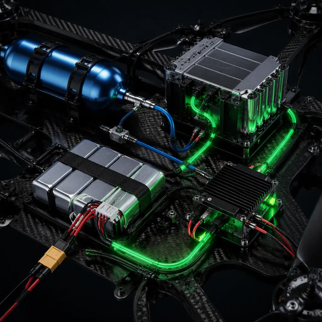
The PEM fuel cell stack, by itself, is an electrochemical reactor that converts hydrogen and oxygen into DC electricity and water — it cannot control its own temperature, cannot supply its own air, cannot manage its own water balance and cannot interface with the UAV's propulsion bus without external subsystems. The balance of plant (BOP) — the air delivery subsystem, the thermal management subsystem, the humidification subsystem, the hydrogen delivery subsystem and the power management unit (PMU) — converts the bare stack into an integrated power system. The procurement team must evaluate the BOP as rigorously as the stack, because a BOP failure (a seized air compressor bearing, a clogged humidifier membrane, an overheated DC-DC converter) disables the power system as completely as a stack failure — and BOP failures are, in practice, more common than stack failures in current-generation UAV fuel cell systems because the BOP components are adapted from automotive and industrial applications whose duty cycles, vibration environments and weight constraints differ from the UAV's.
Air delivery. The PEM stack requires air at 2.0–2.5× the stoichiometric oxygen flow rate to prevent cathode oxygen starvation at the rated power. The oxygen mass flow required for an 850 W stack at 50% efficiency at the rated power point is ṁ_O₂ = P_stack / (η × LHV_H₂) × (MO₂ / (2 × MH₂)), where P_stack = 850 W, η = 0.50, LHV_H₂ = 120 MJ/kg (the lower heating value in joules per kilogram, 33.3 kWh/kg × 3.6 MJ/kWh = 120 MJ/kg), MO₂ = 32 g/mol and MH₂ = 2.016 g/mol — but the oxygen flow is more directly calculated from the stack current. The stack current at 850 W and 0.65 V/cell for a 50-cell stack (32.5 V total) is I = 850 / 32.5 = 26.2 A. Each cell consumes I / (2 × F) = 26.2 / (2 × 96,485) = 1.36 × 10⁻⁴ mol/s of oxygen (F = 96,485 C/mol is Faraday's constant, and the factor of 2 accounts for the two electrons per hydrogen molecule in the anode reaction H₂ → 2 H⁺ + 2 e⁻). For a 50-cell stack, the total oxygen consumption is 50 × 1.36 × 10⁻⁴ = 6.79 × 10⁻³ mol/s = 0.217 g/s of O₂. At the stoichiometric ratio of 2.5, the required oxygen flow is 0.543 g/s, and the required air flow is 0.543 / 0.232 (oxygen mass fraction in dry air) = 2.34 g/s of air. At standard conditions (1.225 kg/m³), the volumetric air flow is 2.34 × 10⁻³ / 1.225 × 60 × 1,000 = 114.5 L/min — within the capability of a small centrifugal blower consuming 15–30 W of electrical power (the 30 W blower power represents 3.5% of the stack's 850 W output, acceptable if the stack efficiency quoted by the supplier is the net efficiency after subtracting the parasitic loads). The procurement specification must require that the supplier quote the stack's net efficiency after subtracting all BOP parasitic loads — the air compressor, the cooling fan, the hydrogen recirculation pump (if used) and the PMU control electronics — at the cruise power operating point, not just the stack's gross efficiency at the membrane electrode assembly (MEA) level.
Thermal management. The PEM stack rejects approximately 40–50% of the hydrogen's LHV energy as heat — at 850 W electrical output and 50% efficiency, the stack generates 850 W of heat that must be rejected to the ambient air to maintain the membrane temperature at 60–70°C (above 80°C, the Nafion membrane begins to dehydrate and lose proton conductivity; below 50°C, the reaction kinetics slow and the stack voltage sags, reducing efficiency). For a fixed-wing UAV cruising at 20 m/s, the ram air through the avionics bay provides forced convection cooling: the heat transfer coefficient from the stack's finned housing to the airflow is approximately h = 50–100 W/(m²·K) at 20 m/s (the Nusselt number correlation for forced convection over a finned cylinder: Nu = 0.683 × Re^0.466 × Pr^(1/3), where Re = ρ × v × D / μ ≈ 1.0 × 20 × 0.1 / (1.8 × 10⁻⁵) ≈ 1.1 × 10⁵ for a 100 mm diameter stack housing, giving Nu ≈ 0.683 × (1.1 × 10⁵)^0.466 × 0.71^(1/3) ≈ 0.683 × 260 × 0.89 ≈ 158, and h = Nu × k / D = 158 × 0.026 / 0.1 ≈ 41 W/(m²·K) — at the low end of the range). With a finned housing surface area of 0.15 m² (typical for a 1 kW air-cooled stack: a 150 mm × 100 mm × 80 mm housing with fins that multiply the base area by 3–5×), the heat rejection capacity at h = 50 W/(m²·K) and ΔT = 30 K (stack at 65°C, ambient air at 35°C — a hot-day scenario) is Q_reject = 50 × 0.15 × 30 = 225 W — less than half of the 850 W of heat generated. This thermal deficit is why UAV fuel cells are typically rated at 500–1,000 W for air-cooled designs — above 1 kW, the heat rejection requirement exceeds what passive air cooling can satisfy, and the system must transition to liquid cooling with a radiator, which adds 0.5–1.5 kg of coolant, pump and radiator mass. For the thermal management practices that apply to UAV power electronics in general — including the heat sink sizing, the thermal interface material selection and the temperature derating curves — the UAV thermal management for electronics guide covers the full heat rejection design methodology.
Water management. The PEM fuel cell's electrochemical reaction produces water at the cathode: O₂ + 4 H⁺ + 4 e⁻ → 2 H₂O. At 850 W electrical output and 50% efficiency, the stack produces ṁ_H₂O = (P_stack / (η × LHV_H₂)) × (MH₂O / MH₂) = (850 / (0.50 × 120 × 10⁶)) × (18.015 / 2.016) = (850 / 60 × 10⁶) × 8.94 = 1.27 × 10⁻⁴ kg/s = 0.46 kg/h of water. This water must be removed from the cathode gas diffusion layer — if it accumulates, it floods the cathode catalyst layer, blocking the oxygen from reaching the reaction sites (a phenomenon called "cathode flooding," which reduces the cell voltage by 50–200 mV and can cause permanent MEA degradation if sustained for more than a few minutes). The air-cooled open-cathode stack design — where the cathode air is supplied by a fan that blows ambient air across the cathode face — uses the cathode air flow to evaporate the product water: the 2.34 g/s of cathode air at the 2.5× stoichiometric ratio, entering at 25°C and 50% relative humidity (an absolute humidity of 10 g of water per kg of dry air), has a water-carrying capacity of 2.34 × 10⁻³ × (20 − 10) = 23.4 mg/s = 0.084 kg/h — far below the 0.46 kg/h of product water. The remaining 0.376 kg/h of water must be removed by a combination of capillary wicking through the gas diffusion layer's hydrophobic PTFE coating (which creates a pressure gradient that drives liquid water from the catalyst layer toward the flow field channel) and periodic "purging" — briefly increasing the cathode air flow to 5–10× stoichiometric for 2–5 seconds every 30–60 seconds to flush accumulated water from the flow field channels. The procurement team must verify that the supplier's water management strategy — passive wicking, active purging or a combination — maintains stable stack voltage over a 4-hour continuous run, documented in the endurance test report with a voltage-vs-time plot at the rated cruise power.
 Concept illustration
Hybrid fuel cell+battery architectures: managing the power transient
The PEM fuel cell is a steady-state power source — its electrochemical response time to a step change in the load current is 0.5–2 seconds, limited by the hydrogen and oxygen transport through the gas diffusion layer to the catalyst sites. A multirotor's power demand changes by 50–200% in 50–200 milliseconds during a wind gust correction (the flight controller commands a motor speed increase → the ESC draws additional current → the propulsion bus voltage sags → the PMU must respond within one control loop cycle of 2.5–5 ms to prevent the bus voltage from dropping below the flight controller's minimum operating voltage of 4.5 V for the 5 V rail). The fuel cell cannot track these transients — a hybrid architecture that pairs the fuel cell with a buffer battery is mandatory for any UAV whose power profile includes transients faster than the fuel cell's 0.5–2 second response time, which is every UAV except a fixed-wing flying in calm air at a constant throttle setting.
Passive hybrid. The simplest hybrid architecture connects the fuel cell's PMU output and the buffer battery directly to the propulsion bus through Schottky diodes that prevent reverse current flow. The fuel cell's PMU regulates its output voltage to a setpoint slightly above the battery's float voltage — for a 12S (44.4 V nominal) propulsion bus with a 10S (37 V nominal) LiPo buffer battery, the PMU regulates to 41.5 V (the 10S battery's float voltage at 4.15 V/cell), and the battery supplies the difference between the propulsion load and the fuel cell's output. During cruise at 600 W, the fuel cell supplies 600 W at 41.5 V / 37 V on the battery side, the battery sees a net current of near zero (the PMU's voltage is at the battery's float voltage, so no charging or discharging occurs), and the fuel cell alone powers the UAV. When a gust demands an additional 400 W for 2 seconds, the propulsion bus current increases → the battery's terminal voltage sags from 41.5 V to 40.5 V at the higher discharge current → the PMU's 41.5 V output is now above the battery voltage → the battery supplies the 400 W transient from its stored energy → the fuel cell continues supplying 600 W. When the gust passes, the propulsion load returns to 600 W → the battery voltage recovers to 41.5 V → the PMU's output matches the battery voltage → the battery stops discharging. If the fuel cell's output exceeds the propulsion load (e.g., during a descent where the motors draw 200 W while the fuel cell produces 600 W), the excess 400 W charges the battery through the Schottky diode — the PMU's 41.5 V output is above the battery's 40.5 V voltage at the end of the gust, so the battery absorbs the excess current. The passive hybrid's advantage is simplicity: no active power management electronics, no communication bus between the fuel cell PMU and the battery BMS, no software that can crash. The disadvantage is that the battery's state of charge (SoC) is not actively managed — the battery charges when the propulsion load is below the fuel cell output, and discharges when it is above, and over a long mission the battery's SoC may drift to 100% (overcharging, which degrades the LiPo cells through electrolyte oxidation at the cathode — the oxidation rate doubles for every 10°C above 25°C and for every 0.1 V above 4.20 V/cell) or to 0% (deep discharge, which causes copper dissolution from the anode current collector and internal short circuits when the copper redeposits as dendrites during recharging). The procurement specification for a passive hybrid system must include a battery SoC management strategy: either the PMU adjusts its output voltage based on the battery SoC (reducing it to 40.0 V when the battery is at 100% SoC to prevent overcharging, increasing it to 42.0 V when the battery is at 20% SoC to force charging), or the flight controller monitors the battery SoC and adjusts the propulsion load (reducing the cruise speed, or switching off non-essential payloads) when the battery SoC falls below a threshold.
Active hybrid. The active hybrid architecture interposes a bidirectional DC-DC converter between the battery and the propulsion bus, controlled by a power management microcontroller that monitors the propulsion bus current, the battery SoC and the fuel cell output power in real time. The microcontroller's control algorithm: (1) maintain the battery SoC within a target range of 40–80% for LiPo (the voltage-vs-SoC curve is steepest in the 20–80% range, giving the best state estimation accuracy from the voltage measurement — above 80%, the voltage changes by < 10 mV per %SoC, making SoC estimation from voltage alone unreliable without coulomb counting), (2) supply the propulsion load's steady-state component from the fuel cell (the average power over a 10-second sliding window, to filter out the wind gust transients), (3) supply the propulsion load's transient component from the battery (the difference between the instantaneous power and the 10-second average), (4) limit the battery's charge and discharge currents to 2C continuous and 5C peak (a 2,500 mAh 10S LiPo at 2C continuous charge/discharge = 5 A at 37 V = 185 W — sufficient for most UAV transient events, which rarely exceed 5 seconds and 500 W peak), (5) if the fuel cell output exceeds the propulsion load and the battery is below 80% SoC, charge the battery at the fuel cell's excess power, limited to 1C (2.5 A) to avoid damaging the LiPo cells through high-rate charging. The active hybrid requires a bidirectional DC-DC converter — a synchronous buck-boost converter using GaN (gallium nitride) FETs for the 100–200 kHz switching frequency that reduces the inductor size from the 50–100 µH required at 20 kHz (silicon MOSFET) to 10–20 µH (GaN FET) — and the converter's mass (0.2–0.4 kg for a 500 W bidirectional converter) must be included in the system mass budget. The procurement team evaluating an active hybrid system must verify that the supplier provides the control algorithm's source code or a detailed functional specification — a black-box power management unit whose control logic cannot be audited is unacceptable for a BVLOS UAV whose flight safety depends on the power system's behaviour during a fuel cell failure (the PMU must detect the fuel cell output dropping below the cruise power and switch the propulsion load to the battery within 50 ms, before the propulsion bus voltage sags below the flight controller's brownout threshold).
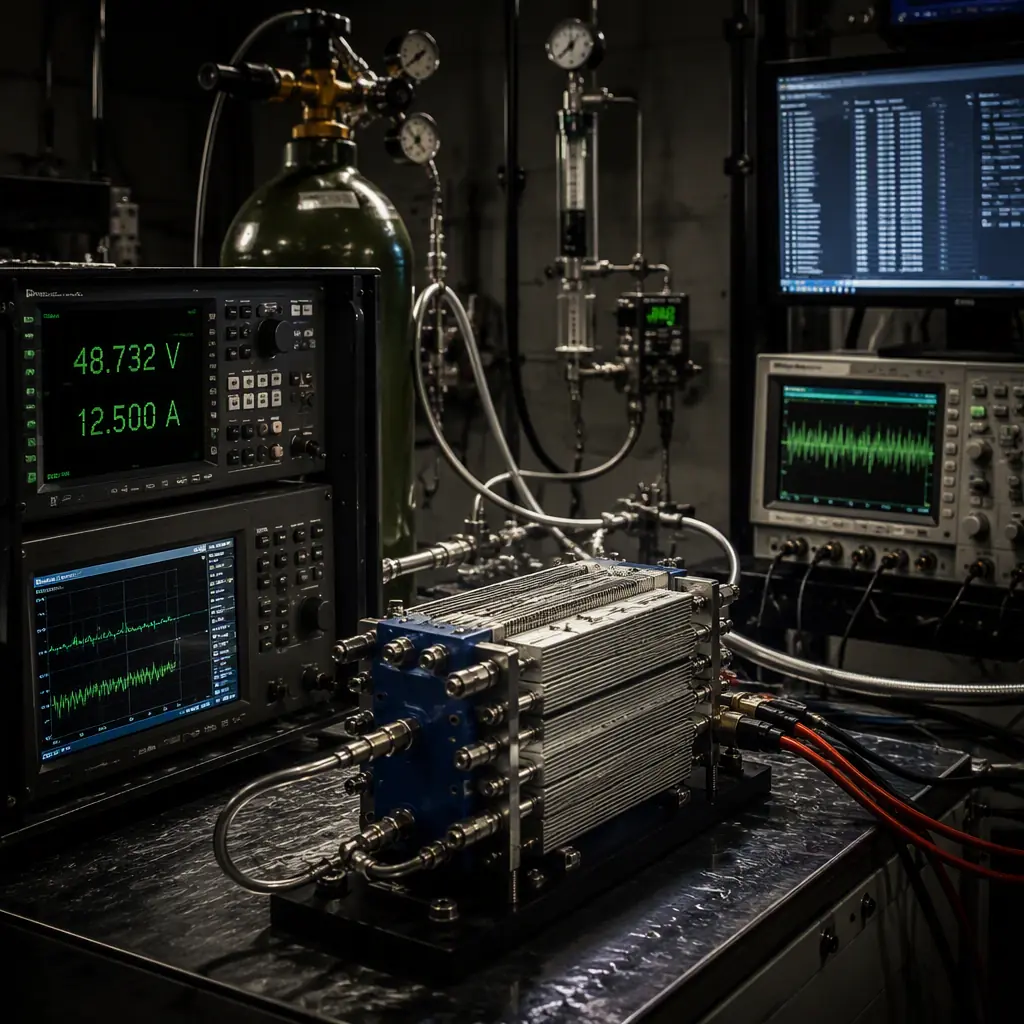 Concept illustration
Certification and safety: hydrogen handling for aviation operations
The certification pathway for a hydrogen fuel cell UAV propulsion system depends on the UAV's regulatory category — civil (operated under the aviation authority's unmanned aircraft regulations), experimental (operated under an experimental certificate or a special flight operations certificate) or military (operated under the defence authority's airworthiness framework). For civil operations, the predominant certification standards are ASTM F3298 (Standard Specification for Design, Construction and Verification of Lightweight Unmanned Aircraft Systems) in the United States and EASA SC-RPAS (Special Condition for Remotely Piloted Aircraft Systems) in Europe — neither of which contains hydrogen-specific requirements as of 2026, meaning that the certification authority will apply the existing hydrogen safety standards developed for ground vehicles and stationary power systems: ISO 19880-1 (Gaseous Hydrogen — Fuelling Stations), SAE J2601 (Fueling Protocols for Light Duty Gaseous Hydrogen Surface Vehicles), and the hydrogen-specific sections of IEC 62282 (Fuel Cell Technologies). The procurement team must require that the fuel cell system supplier provide a compliance matrix mapping each of the hydrogen-specific requirements in these standards to the system's design features and test evidence — and must verify that the compliance matrix covers the failure modes that are unique to UAV operations: a crash impact on the hydrogen cylinder, a fuel cell stack fire during an in-flight thermal runaway, and a hydrogen leak inside the avionics bay during a BVLOS mission where the operator cannot initiate an emergency landing for 5–10 minutes (the communication latency over a satellite or 4G/LTE link).
Cylinder certification. The hydrogen storage cylinder must be certified to a pressure vessel standard that the aviation authority accepts: UN/ISO 11119-3 (Gas Cylinders — Refillable Composite Gas Cylinders, Part 3: Fully Wrapped Fibre Reinforced Composite Gas Cylinders with Non-Load Sharing Metallic or Non-Metallic Liners) for Type 3 and Type 4 cylinders, or the U.S. Department of Transportation (DOT) CFFC (Carbon Fiber Fully Wrapped Composite) specification for cylinders used in the United States. The certification test sequence includes: a hydrostatic pressure test at 1.5× the rated working pressure (525 bar for a 350 bar cylinder) to verify the cylinder's burst margin (the minimum burst pressure must be ≥ 2.25× the rated working pressure = 787.5 bar for a 350 bar cylinder, and the cylinder must not rupture below 1.5×); a cycle test (5,000 pressurization cycles from 20 bar to 350 bar at a rate of ≤ 10 cycles per minute, to simulate the fatigue loading from repeated refueling — a UAV cylinder that is refueled once per flight and flies 500 missions per year accumulates 500 cycles per year, so the 5,000-cycle certification provides a 10-year service life with a 10× safety factor on the fatigue life); and a bonfire test (the cylinder pressurized to the rated working pressure and exposed to a propane fire for 30 minutes — the cylinder must vent its contents through the thermally-activated pressure relief device (PRD) without rupturing, and the PRD must activate within 10 minutes of fire exposure). The procurement specification must require that the cylinder's certification documents include the date of manufacture (the cylinder's composite overwrap has a 15–20 year service life from the date of manufacture, limited by the epoxy matrix's creep and stress-rupture behaviour under sustained pressure loading), the last hydrostatic retest date (required every 5 years for composite cylinders per UN/ISO 11119-3, Section 7.3.2), and the PRD's activation temperature (typically 100–110°C for a eutectic solder plug PRD, which melts at the activation temperature and opens the vent port — the procurement team must verify that the PRD's activation temperature is below the carbon fiber/epoxy composite's glass transition temperature Tg of 120–140°C, because the composite loses 50–70% of its tensile strength above Tg and may rupture before the PRD activates if the PRD temperature is set too high).
Hydrogen leak detection and mitigation. Hydrogen's lower flammability limit (LFL) in air is 4.0% by volume, and its minimum ignition energy is 0.017 mJ — approximately 10× lower than methane's 0.28 mJ and 15× lower than gasoline vapour's 0.25 mJ, meaning that a hydrogen leak can be ignited by a static discharge from the UAV's plastic airframe (a 5 kV human-body-model ESD discharge delivers approximately 0.5 mJ — 30× the hydrogen ignition energy). The fuel cell system must include a hydrogen concentration sensor in the avionics bay (an electrochemical or thermal conductivity sensor with a measurement range of 0–4% H₂ by volume, a response time of ≤ 5 seconds to reach 90% of the final reading, and an accuracy of ±0.2% H₂ at the 1% alarm threshold) and an automatic safety shutdown sequence: if the H₂ concentration exceeds 25% of LFL (1.0% H₂ by volume), the system must close the hydrogen supply solenoid valve (a normally-closed valve that opens only when energized — a loss of electrical power automatically closes the valve, providing a fail-safe shutdown), purge the stack's anode compartment with nitrogen or the cathode air (flushing the residual hydrogen out of the stack within 30 seconds), notify the flight controller of the hydrogen alarm (through a digital output or a CAN bus message — the flight controller should initiate an immediate return-to-launch or an emergency landing if the H₂ concentration exceeds 50% of LFL at 2.0% H₂), and continue monitoring the H₂ concentration for 10 minutes after the shutdown to detect any continuing leak from the cylinder valve or the pressure regulator (the cylinder's manual isolation valve — the valve on the cylinder boss that the operator opens before flight — should be separate from the solenoid valve so that a solenoid valve failure does not prevent the operator from manually isolating the cylinder after landing). The procurement specification must require that the supplier demonstrate the leak detection and shutdown sequence during the acceptance test: inject 1.5% H₂ into the avionics bay (using a calibrated gas mixture from a test cylinder) and verify that the solenoid valve closes within 5 seconds of the sensor reaching the 1.0% alarm threshold, that the stack anode purges within 30 seconds, and that the flight controller receives the hydrogen alarm message within 1 second of the alarm threshold crossing.
For the full certification documentation package — including the CE Declaration of Conformity, the FCC equipment authorization, the NDAA Section 848 compliance statement and the supplier's quality management system certification — the UAV certification and compliance guide covers the regulatory documentation framework that applies to all UAV subsystems, including the additional hydrogen-specific certification requirements covered in this section. For the electromagnetic compatibility requirements that apply to the fuel cell's power electronics — the DC-DC converter's conducted and radiated emissions, and the stack's susceptibility to the UAV's telemetry radio and video transmitter RF fields — the UAV avionics EMC/EMI design and compliance guide covers the emissions and immunity standards.
Procurement checklist: specifying a hydrogen fuel cell power system
The following eight-line-item procurement specification translates the technical analysis in Sections 1–6 into a checklist that the procurement team can include in the RFQ. Each line item includes the verification method — how the procurement team confirms that the supplier has met the requirement before accepting delivery.
1. System-level specific energy. The fuel cell power system — including the stack, the balance of plant (air compressor, cooling fan, humidifier, hydrogen recirculation pump if used, power management unit), the hydrogen storage (cylinder or chemical hydride cartridge with the regulator/valve assembly), and the buffer battery (if the architecture is hybrid) — shall deliver a usable DC electrical energy density of ≥ 400 Wh/kg at the system level at the cruise power operating point. Verification: the supplier shall provide a test report from an ISO/IEC 17025 accredited laboratory (or, if laboratory testing is not available for the system's power level, an in-house test report with the test equipment calibration certificates and the raw data) documenting a continuous run of ≥ 2 hours at the cruise power, with the system mass measured on a calibrated scale (±1 g accuracy) before the run and the total DC energy output measured by a calibrated power analyzer (±0.5% accuracy) integrated over the run duration. The system mass shall include all components that are mounted on the UAV — the stack, the BOP, the full hydrogen cylinder or cartridge, the PMU and the buffer battery — and shall not include the ground support equipment (the refueling station, the external power supply for the startup sequence, or the ground control station).
2. Stack rated power and voltage range. The stack shall produce a continuous net DC output power of ≥ [procurement team to specify, based on the mission power analysis in Section 2] watts at an output voltage of [24–48] V DC, with the voltage at the rated power within the range of 24–42 V to ensure compatibility with standard UAV propulsion bus power management units. Verification: the supplier shall provide a polarization curve (voltage vs current) measured at the stack's DC output terminals (after the stack, before the PMU) at the rated operating temperature of 65 ± 5°C, with the cathode air supplied at the rated stoichiometric ratio of 2.0–2.5, documented in the acceptance test report.
3. Startup time. The stack shall reach 90% of the rated power within ≤ [60–120] seconds from the opening of the hydrogen supply valve, at an ambient temperature of 20 ± 5°C. Verification: the supplier shall provide a startup transient plot — stack output power vs time, from t = 0 (valve opening command) to t = 120 seconds — with the data sampled at ≥ 1 Hz, documented in the acceptance test report.
4. Hydrogen storage certification. The hydrogen storage cylinder shall be certified to UN/ISO 11119-3 (or the equivalent national standard accepted by the aviation authority in the country of operation), with the certification documentation including the date of manufacture, the last hydrostatic retest date (within 5 years of the delivery date) and the pressure relief device (PRD) activation temperature. Verification: the supplier shall provide a copy of the cylinder's certification certificate from the accredited inspection body, the cylinder's serial number (which must match the serial number stamped on the cylinder boss) and the hydrostatic retest report.
5. Hydrogen leak detection. The fuel cell system shall include a hydrogen concentration sensor that triggers the automatic safety shutdown sequence (solenoid valve closure, anode purge, flight controller notification) when the H₂ concentration in the avionics bay exceeds 1.0% by volume (25% of the lower flammability limit). Verification: the supplier shall demonstrate the leak detection and shutdown sequence during the factory acceptance test, with the H₂ concentration, the valve state and the flight controller notification message recorded on a data acquisition system at ≥ 10 Hz sampling rate. The time from the sensor crossing the 1.0% H₂ threshold to the solenoid valve closing shall be ≤ 5 seconds.
6. Endurance test. The fuel cell power system shall complete a continuous run of ≥ [mission endurance + 30 minutes] at the cruise power operating point without a stack voltage degradation of more than 5% from the initial value at the start of the run. Verification: the supplier shall provide a voltage-vs-time plot for the full endurance run duration, with the voltage measured at the stack's DC output terminals and the data sampled at ≥ 0.1 Hz (one sample every 10 seconds). The voltage at the end of the run shall be ≥ 95% of the voltage at t = 60 seconds (after the startup transient has settled), and the plot shall show no sustained voltage oscillations of > 2% peak-to-peak (indicating water management instability — the periodic purging should produce voltage dips of ≤ 1% of the nominal voltage for ≤ 5 seconds, and the voltage should recover to the pre-purge level within 10 seconds).
7. Electromagnetic compatibility. The fuel cell system's power electronics — the PMU's DC-DC converter, the air compressor's brushless DC motor driver and the solenoid valve driver — shall comply with the conducted and radiated emissions limits of CISPR 32 Class A, 150 kHz–30 MHz conducted and 30 MHz–6 GHz radiated, measured at 3 metres. Verification: the supplier shall provide an EMC test report from an ISO/IEC 17025 accredited laboratory, or a pre-compliance test report with the test setup photographs, the equipment calibration certificates and the ambient noise floor measurement (demonstrating that the ambient noise is ≥ 6 dB below the limit line). This requirement is critical for UAV applications where the GPS receiver and the telemetry radio operate within 10–30 cm of the fuel cell's power electronics — radiated emissions from the PMU's 100–200 kHz switching frequency and its harmonics can desensitize the GPS receiver and corrupt the MAVLink telemetry data if the emissions exceed the CISPR 22 Class A limits by more than 10 dB.
8. Supplier production quality. The supplier shall demonstrate a production quality system that maintains the consistency of the stack's electrochemical performance across production batches — a variation of > 5% in the stack's polarization curve between production units indicates a process control issue (a variation in the membrane electrode assembly catalyst loading, the gas diffusion layer compression, or the bipolar plate flow field channel dimensions). Verification: the supplier shall provide the polarization curves for the last 10 production units of the same model, with the mean and the ±3σ limits plotted on the same graph. The ±3σ voltage variation at the rated current density shall be ≤ 5% of the mean voltage — equivalent to the stack power variation of ≤ 5% at the rated current.
For the supplier evaluation framework that the procurement team should use to audit the fuel cell supplier's overall quality management system — including the ISO 9001 certification, the IPC-A-610 Class 3 acceptance criteria for the power electronics assembly and the first-article inspection requirements — the UAV supplier evaluation checklist covers the five-step audit methodology that applies to all UAV component suppliers, including the additional hydrogen-specific criteria covered in this section. For the system-level acceptance test that verifies the fuel cell power system's performance when integrated into the complete UAV — the end-to-end test that includes a full-mission profile with the takeoff, cruise, loiter and landing power transients — the UAV propulsion testing and validation guide covers the acceptance test procedures that apply to all propulsion systems, including the fuel-cell-specific test points (startup transient, hydrogen alarm simulation, endurance run and battery SoC management verification).
Explore custom engineering Back to Blog
Continue Reading
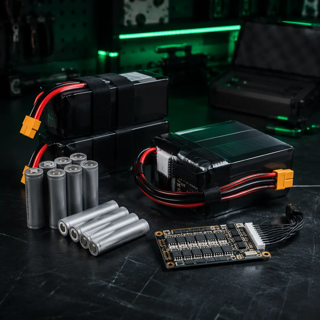
UAV Battery Power Management Guide
The LiPo and Li-Ion pack sizing methodology, BMS selection and charging infrastructure decisions that form the battery side of the propulsion trade study against hydrogen fuel cells.
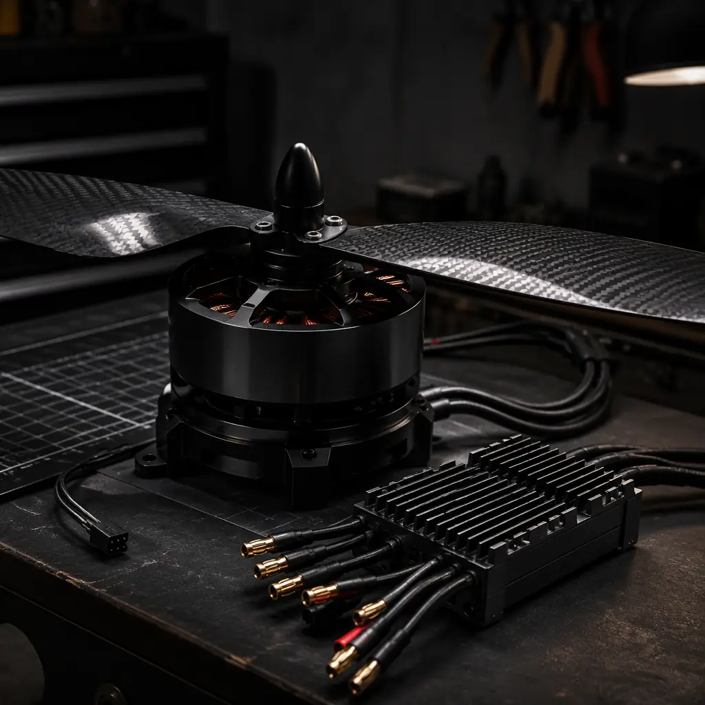
UAV Heavy-Lift Propulsion Design
The motor, ESC, propeller and battery architecture for UAVs above 25 kg — the propulsion bus design that the fuel cell PMU must interface with at 12S–14S voltage levels.
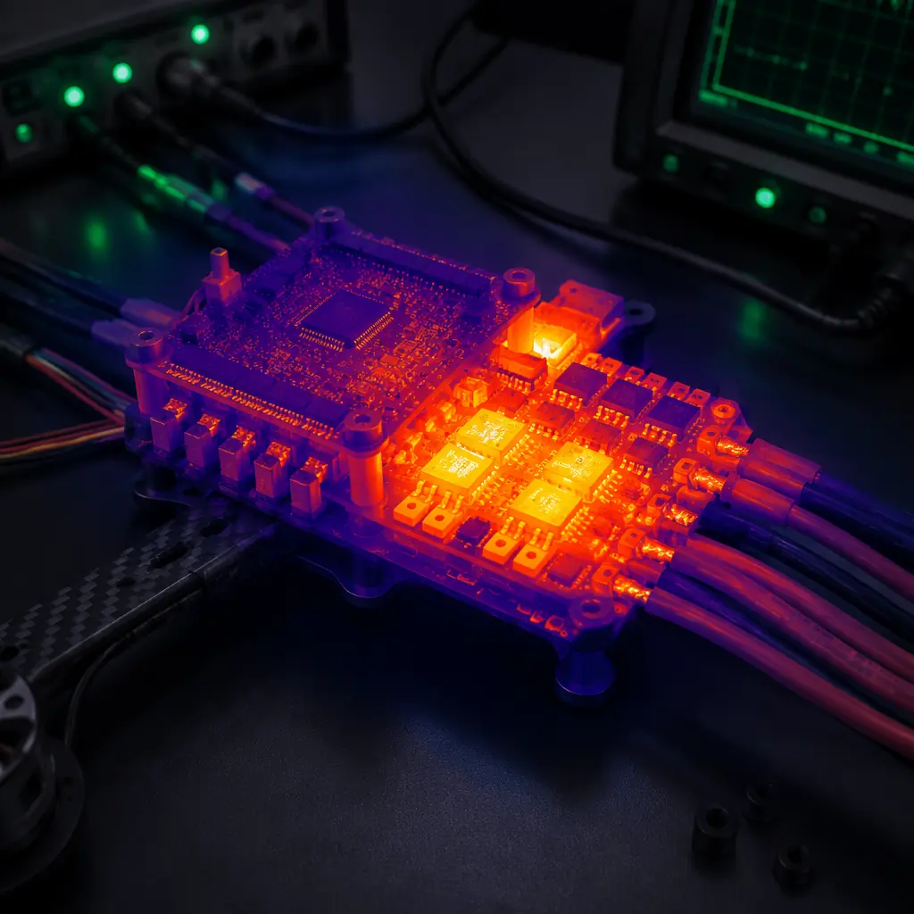
UAV Thermal Management for Electronics
The heat sink sizing, thermal interface material selection and cooling strategy for UAV power electronics — including the 850 W of heat rejected by a 1 kW fuel cell stack at 50% efficiency.
UAV Certification & Compliance Guide
The CE, FCC, NDAA and aviation authority certification framework — the regulatory documentation that must accompany the fuel cell system's cylinder certification and EMC test reports.
UAV Supplier Evaluation Checklist
The five-step audit methodology for UAV component suppliers — ISO 9001, IPC-A-610 Class 3, first-article inspection and lot traceability, applied to the fuel cell system supplier.