
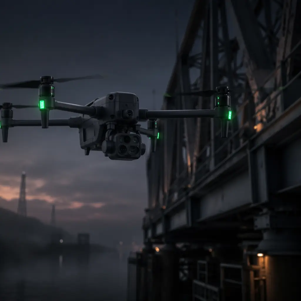
Industrial inspection drones operate in environments that punish every shortcut. A bridge inspection at 60 meters AGL in 25 km/h gusting crosswinds, a flare stack survey at 120 meters with 800°C thermal updrafts, a power line corridor spanning 40 kilometers with no intermediate landing zones. These are not the conditions you simulate on a bench. The component choices you make at procurement stage determine whether the aircraft completes the mission or becomes a recovery operation.
The inspection UAV market was valued at approximately USD 4.2 billion in 2025 and is projected to reach USD 12.6 billion by 2032, driven by tightening asset integrity regulations across the energy, transportation and telecommunications sectors. But market growth does not translate into successful deployments. A 2024 survey of 140 European infrastructure operators found that 43% of early inspection drone programs experienced at least one mission-critical component failure within the first six months, and 78% of those failures traced back to component selection errors rather than manufacturing defects. The components were functional; they were simply the wrong components for the mission.
This article approaches inspection drone component selection from the perspective of a procurement engineer who needs to specify hardware today, not a futurist describing what inspection drones might do in five years. Every recommendation is tied to a measurable performance parameter you can validate on a datasheet or a test bench. The foundational architecture concepts, how control, power, propulsion and payload layers must be planned as one interface map, are established in the UAV supply chain layers framework. If you have not read that article, start there; this article assumes you understand the layered architecture and are now selecting components within it.
Flight controllers for inspection: stability above all else
The flight controller on an inspection drone does not need aggressive acrobatic modes, 8 kHz gyro update rates for racing, or Betaflight-level tunability. What it needs is precise position hold under gusting wind, smooth altitude transitions when crossing thermal boundaries, and reliable failsafe behavior when the aircraft loses line of sight behind a cooling tower or inside a confined space. These requirements point to a specific class of flight controllers running ArduPilot or PX4 on STM32H7-series processors with redundant IMUs.
The critical specification is not the loop rate, 400 Hz is adequate for inspection flight dynamics, but the quality of the Extended Kalman Filter (EKF) sensor fusion. An inspection drone hovering at 3 meters from a bridge girder in gusting conditions needs the EKF to maintain position accuracy within 0.3 meters horizontally and 0.15 meters vertically. A standard H7 flight controller with dual ICM-42688-P IMUs (vibration-resistant MEMS, 40g shock rating) and two GNSS receivers, one L1/L2 RTK for absolute positioning, one L1 for redundancy, achieves this in wind speeds up to 12 m/s. Above 12 m/s, consider adding an external optical flow sensor or a laser rangefinder for terrain-relative navigation.
Redundancy is not optional for inspection missions where a flight controller reset means a 15 kg aircraft free-falling onto critical infrastructure. The minimum configuration is a flight controller with a separate power management unit (PMU) that provides regulated 5.3V and 3.3V rails with independent overcurrent protection per rail, plus a backup power path from a secondary battery through a diode-OR circuit. If the primary BEC fails, the backup continues supplying the flight controller without interruption, the pilot sees a telemetry warning, not a falling aircraft. For the ESC and motor interface details that feed into the flight controller's attitude control loop, the flight controller and ESC matching guide covers protocol selection and timing constraints.
 Concept illustration
Payload architecture: sensor selection and electrical isolation
The payload is what makes an inspection drone an inspection drone. For most industrial inspection missions, bridges, power lines, pipelines, cell towers, wind turbine blades, the baseline payload is a dual-sensor gimbal carrying a radiometric thermal camera (640 × 512 resolution minimum, ≤50 mK thermal sensitivity) alongside a visible-light camera with 20× or greater optical zoom. The gimbal must achieve ≤0.02° angular stabilization accuracy; anything looser produces visible jitter in the thermal feed at 30× zoom, rendering defect identification unreliable.
Payload power isolation is the single most common failure point. A 3-axis gimbal with active cooling, two cameras streaming simultaneously and a laser rangefinder draws 35–55 W peak, and the inrush current when the gimbal motors initialize triple that draw for approximately 200 ms. If the payload shares a power rail with the flight controller, that inrush transient pulls the rail voltage below the flight controller's brown-out threshold (typically 4.5V on a 5V rail), triggering a watchdog reset. The solution is a dedicated payload BEC with its own input capacitor bank (≥2,000 μF low-ESR) and a separate ground return path. A configuration that adds approximately 45 grams and costs less than the 30-minute investigation required to diagnose a single brown-out incident.
For electromagnetic compatibility, the gimbal's three brushless motors switching at 16–32 kHz PWM create broadband noise from 30 MHz to 1 GHz, precisely the bands occupied by GNSS L1 (1,575.42 MHz), telemetry radios (868/915 MHz, 2.4 GHz) and the inspection drone's own video downlink (typically 2.4 GHz or 5.8 GHz). Physical separation is the primary defense: mount the GNSS antenna at least 25 cm from the gimbal motors, with a ground plane between them. Ferrite chokes on all payload power and data cables provide 15–25 dB of common-mode attenuation above 100 MHz, enough to bring the noise floor at the GNSS antenna below -130 dBm, the threshold where satellite tracking becomes unreliable. The broader RF coordination requirements across all onboard radios are covered in the UAV RF communication systems guide.
Payload integration extends beyond the gimbal to the data pipeline. A thermal camera recording at 30 fps in radiometric mode generates approximately 4–6 GB of data per flight hour, too much for a standard UART telemetry link at 115,200 bps (∼14 KB/s). The solution is either onboard storage (512 GB industrial-grade microSD with ≥U3 speed rating, formatted as exFAT for file sizes exceeding 4 GB) or a dedicated Ethernet/IP downlink at 50–100 Mbps for real-time defect review by a remote engineer. The architectural decision between onboard recording and live downlink determines cable weight, connector specification and electromagnetic shielding strategy. And it must be made before selecting a single component. For the mechanical integration considerations that govern payload mounting, vibration isolation, CG placement and structural stiffness, see the UAV payload integration guide.
 Concept illustration
Power systems for endurance inspection missions
Industrial inspection missions demand flight times that push battery technology to its limits. A typical power line corridor inspection covers 15–25 km per sortie, requiring 35–55 minutes of flight time including hover segments for close-up imaging at each tower. A bridge inspection with underside access requires 25–40 minutes of precision hovering with frequent altitude changes. Neither mission can be completed with a 6S 10,000 mAh LiPo that delivers 18–22 minutes of practical endurance under inspection flight profiles, the constant throttle modulation during hover and translation burns 25–35% more energy per minute than steady forward flight.
The battery architecture for inspection drones has converged on high-voltage configurations: 12S (44.4V nominal) or 14S (51.8V nominal) Li-Ion packs using 21700 cells (Samsung 50S or Molicel P42A), delivering 20,000–28,000 mAh capacity in a 3.2–3.8 kg pack. At 12S, the lower current draw (approximately 25–35A in hover for a 12 kg aircraft vs. 50–70A at 6S) reduces I²R losses in the power distribution system by approximately 75%, directly translating to 8–12 additional minutes of flight time from the same watt-hour capacity. This is not a marginal gain. It is the difference between completing the inspection corridor and landing short with 4 towers remaining.
Cell-level monitoring becomes critical when the battery is the single point of failure. An inspection drone equipped with a BMS that monitors individual cell voltages at 100 ms intervals, with programmable low-voltage per-cell thresholds (2.8V for Li-Ion under load) and automatic RTL (return-to-launch) triggering when any cell drops below threshold for more than 3 seconds, prevents the most common inspection mission failure mode: the aircraft running out of energy 800 meters from the landing zone because the pilot was watching the thermal feed and missed the battery warning. The component-level specifics of Li-Ion vs. LiPo cell selection, BMS architecture and thermal management strategies for high-endurance platforms are detailed in the UAV battery and power management guide.
Airframe considerations for inspection environments
The inspection environment dictates the airframe material choice more than any other factor. A drone inspecting flare stacks at an oil refinery operates in ambient temperatures of 50–70°C with occasional exposure to radiant heat spikes exceeding 250°C. An aluminum airframe at these temperatures expands by approximately 0.5–0.8 mm across a 600 mm motor-to-motor span. Enough to shift the motor thrust vectors and introduce a yaw bias the flight controller must constantly compensate for. Carbon fiber, with a coefficient of thermal expansion (CTE) of approximately -0.1 to 2 ppm/°C versus aluminum's 23 ppm/°C, maintains dimensional stability across the full temperature range. The structural trade-offs, stiffness, weight, vibration damping and repairability, across carbon fiber, aluminum and composite airframe materials are analyzed in detail in the UAV airframe materials guide.
For confined-space inspection, storage tanks, pressure vessels, underground tunnels, the airframe must protect the propellers from contact damage. A full carbon fiber propeller guard cage adds 350–600 grams but prevents the most common confined-space failure: a propeller tip striking a wall, shattering, and unbalancing the motor within 0.5 seconds, triggering an immediate attitude loss. The guard cage material matters: injection-molded nylon guards survive one impact and crack; CNC-machined polycarbonate or carbon-fiber guards absorb multiple impacts without structural failure. The weight penalty of the heavier guard is offset by reducing the collision risk to near zero. The alternative is retrieving a damaged aircraft from inside a 30-meter chemical storage tank.
 Concept illustration
Communications: the inspection data pipeline
Inspection drones generate more data than any other commercial UAV category, and the communications system must be architected to handle three simultaneous streams: command and control (C2) telemetry, video downlink, and payload data. C2 telemetry at 10 Hz with full MAVLink 2 message packing requires approximately 15–20 kbps per second, easily handled by any 868/915 MHz SiK radio. The video downlink, however, demands 8–15 Mbps for a single 1080p30 H.264 stream, and 25–40 Mbps for dual-stream thermal-plus-visible with frame-synchronized metadata. This bandwidth requirement pushes the communications architecture toward 2.4 GHz or 5.8 GHz digital video transmission systems with MIMO antenna diversity.
The frequency band decision is governed by the inspection environment. A 2.4 GHz video downlink delivers excellent bandwidth (up to 50 Mbps) in open air but degrades rapidly near metallic structures, bridges, transmission towers, storage tanks, because 2.4 GHz reflects off metal surfaces creating multi-path interference that manifests as video dropouts at specific aircraft orientations. A 5.8 GHz system attenuates more quickly with distance but penetrates gaps between structural elements with less multi-path distortion because the shorter wavelength (∼5.2 cm vs. ∼12.5 cm for 2.4 GHz) diffracts less around edges. For inspection missions within 500 meters of the ground station near heavy steel infrastructure, 5.8 GHz with circularly polarized antennas and automatic frequency hopping across at least 8 channels provides the most reliable video link. For long-range corridor inspection, power lines, pipelines, 868/915 MHz SiK radios for C2 combined with 1.2–1.3 GHz analog video (or digital COFDM at those frequencies where regulations permit) provides 10–15 km range at the cost of lower video resolution.
The antenna placement on an inspection drone is a mechanical integration problem disguised as an RF problem. A GNSS antenna mounted 5 cm from a 1W 868 MHz telemetry radio will see approximately -20 dBm of leakage from the telemetry transmitter, enough to desensitize the GNSS receiver's LNA and drop 3–5 satellites. The minimum separation is 30 cm between any transmitting antenna and the GNSS antenna, with the GNSS antenna on top and all transmitting antennas on the bottom of the aircraft. The RF fundamentals, link budget calculation, antenna gain vs. coverage pattern, and interference management across frequency bands, are covered in the UAV RF communication systems article.
Procurement checklist: 8 component decisions before ordering
The following checklist distills the component selection process into eight decisions you can validate against a datasheet before placing an order. Each item maps to a specific inspection mission risk.
1. Flight controller processor and IMU redundancy. Verify STM32H7-series or equivalent processor with dual ICM-42688-P or ICM-45686 IMUs (not single IMU on a budget FC). Confirm the EKF supports dual GNSS input with automatic failover. Budget FCs with single BMI270 IMUs and no GNSS redundancy are inadequate for inspection missions where position hold failure means collision with a multi-million-dollar asset.
2. Gimbal angular stabilization accuracy. ≤0.02° on both pitch and yaw axes, verified from the gimbal manufacturer's test data at the expected payload mass, not from the marketing specification sheet (which typically quotes performance with an unloaded gimbal on a vibration-isolated bench). A 0.05° gimbal that the manufacturer rates at 0.02° will produce visible image jitter at 20× zoom on an actual aircraft.
3. Payload power isolation. Dedicated BEC with ≥25% current headroom above the payload's measured peak draw (not rated draw. Measure it with a current probe during gimbal initialization), ≥2,000 μF input capacitance, and a ground return path that does not share a trace or wire segment with the flight controller ground. Validate by monitoring the flight controller's Vcc rail with an oscilloscope during gimbal power-on: any sag below 4.5V on a 5V rail fails the test.
4. Battery configuration. 12S or 14S Li-Ion with 21700 cells, BMS with per-cell monitoring at ≤100 ms interval, programmable low-voltage RTL trigger. Total battery mass should be 25–35% of MTOW for inspection endurance (higher fraction = more endurance but less payload capacity and wind tolerance). A 12 kg class inspection drone with a 3.5 kg 12S8P 21700 pack achieves 42–50 minutes of inspection flight time.
5. Propeller and motor matching. Large-diameter, low-pitch propellers (22–26 inch, 5.5–7.0 inch pitch) paired with low-KV motors (100–200 KV at 12S) for inspection endurance. The thrust-to-weight ratio target is 2.0–2.5:1 at 50% throttle, not the 4:1+ common in cinematography drones. Inspection missions do not need aggressive climb rates, they need efficient hover. The full matching methodology across the motor-ESC-propeller chain is in the UAV powertrain matching guide.
6. Airframe material and thermal tolerance. Carbon fiber for high-temperature environments (flare stacks, refinery, desert solar farms). G10/FR4 or polycarbonate for confined-space inspection where impact resistance matters more than thermal stability. Verify the airframe manufacturer's published glass transition temperature (Tg) for any bonded joints, epoxy bonds in G10 begin to soften at 120–140°C, well within the radiant heat range near a flare stack.
7. Video downlink frequency and antenna separation. 5.8 GHz with circular polarization and ≥8-channel frequency hopping for short-range (< 500 m) structural inspection. 868/915 MHz for C2 telemetry, physically separated from the video transmitter by ≥15 cm. GNSS antenna ≥30 cm from any transmitting antenna with a ground plane between them. Validate with a spectrum analyzer sweep at the GNSS antenna position during full-power transmission.
8. Weather sealing and ingress protection. Minimum IP43 for the flight controller and power distribution enclosure (protected against spraying water and ≥1 mm solid objects). IP54 for connectors exposed to rain or condensation. Conformal coating on all PCBs (acrylic or silicone-based, 25–50 μm thickness) prevents the condensation failures that occur when a cold-soaked drone flies into warm, humid air near a cooling tower plume, a specific failure mode that accounts for approximately 12% of inspection drone electrical failures according to operator surveys.
For teams deciding between assembling components from individual suppliers versus procuring a pre-integrated subsystem, the decision framework in the UAV component build vs. buy guide provides a structured cost-benefit analysis across the three sourcing depths, individual components, matched subsystems, and complete aircraft.
Cost structure: what an inspection payload really costs to integrate
Inspection platforms attract an unusual budgeting error: the sensor is priced carefully and the integration around it is treated as a detail. In practice the integration is where the schedule goes, because a thermal or visual sensor that meets its own datasheet can still fail to deliver usable inspection data once it is mounted on a vibrating airframe with a contested power rail and a link that has to carry both the imagery and the telemetry. The table below shows how the cost of an inspection payload integration typically splits on 5-25 kg multirotor platforms.
| Cost line | Typical share | What drives it up | Where inspection projects overspend |
|---|---|---|---|
| Imaging sensor and optics | 25-35% | Radiometric accuracy, lens resolution matched to standoff distance, shutter type | The visible specification is well understood; the radiometric and stabilisation requirements are discovered in the field |
| Gimbal and stabilisation | 18-25% | Vibration isolation, gimbal stiffness, pointing accuracy at the required angular resolution | Under-specified relative to the sensor, then retro-fitted after the first blurred dataset |
| Power conditioning and isolation | 8-12% | Separate regulated rail, filtering, inrush handling | Sharing an avionics rail causes sensor noise and intermittent dropouts that are hard to attribute |
| Data link and storage | 12-18% | Downlink bandwidth for live streaming, onboard storage for full-resolution capture | The link is sized for the preview stream, not the archive, so full-resolution data has to be retrieved by hand |
| Mounting and airframe integration | 10-15% | Hard points, isolation pads, drag and CG compensation | CG shift after adding a nose-mounted sensor is a recurring and avoidable issue |
| Ground processing and calibration | 8-12% | Calibration targets, radiometric reference, software licences, analyst time | Usually excluded from the hardware budget entirely, then appears as an operational surprise |
The recurring pattern is that the sensor is chosen on optical specification and the stabilisation, power isolation and link are sized after it. Standing that sequence on its head, by fixing the required angular resolution and the radiometric accuracy first and then deriving the gimbal and link requirements from those, removes most of the reassembly that otherwise happens after the first inspection flight.
What an inspection payload actually costs to build
The component decisions above only resolve into a procurement plan once they carry real numbers. The bands below are what we see on inspection payloads built around a 640×512 radiometric thermal core with a stabilised gimbal, quoted as integration cost at the component level.
| Cost item | Typical band (USD) | What drives it |
|---|---|---|
| Thermal core and lens | 4,500 – 12,000 | Resolution, radiometric calibration, lens field of view |
| Stabilised gimbal | 2,800 – 8,500 | Axis count, payload mass, vibration rejection spec |
| Payload electronics and isolated rails | 900 – 2,600 | Whether a dedicated supply rail is mandatory |
| Mount, isolation and standoff hardware | 500 – 1,600 | Airframe vibration spectrum, required mount frequency band |
| Calibration and radiometric traceability | 700 – 2,100 | Reference source, re-calibration interval |
| Integration and airworthiness work-up | 1,800 – 5,000 | Whether a target board and standoff trial are included |
The line most often underestimated is calibration and radiometric traceability. It looks like a service cost, but a radiometric payload without a documented reference cannot be used for a temperature judgement in an inspection report, which means the whole payload is written off for that class of work. Settling the calibration obligation against a configured quotation at the start is cheaper than discovering it at first flight.
Responsibility split: supplier and operator on an inspection platform
An inspection payload procurement fails when this split is implicit. This is the division we hold to, and the one to write into the order.
| Item | Supplier responsibility | Operator responsibility |
|---|---|---|
| Defect detection performance | State the achieved angular resolution and standoff for the delivered lens | Define the smallest defect and the standoff the aircraft will hold |
| Radiometric accuracy | Supply the calibration state, reference and accuracy statement | Respect the re-calibration interval and record it |
| Vibration environment | Declare the mount frequency range and isolation spec | Supply the airframe vibration spectrum and confirm the mount fits |
| Power and isolation | State the supply conditions and rail requirement | Provide the dedicated rail if it is declared mandatory |
| Metadata completeness | Write position, orientation and calibration reference with each frame | Retain the archive and verify the metadata on ingest |
| Firmware change effect | Notify any change affecting image geometry, radiometric scaling or metadata | Re-validate the affected payload set before the next survey campaign |
As on any safety-relevant payload, the firmware row matters most. A firmware update that silently changes radiometric scaling invalidates every temperature reading taken afterwards, so the notification obligation has to be a contractual term rather than a courtesy. It maps back to a step in our production and verification process, which is why we require it in writing.
Two real builds: where the inspection numbers came from
Both reference builds below were engineered on the same component architecture this page describes, and the figures are measured rather than estimated. They are drawn from the projects we have actually built.
- A VTOL fixed-wing mapping platform carries a 5 kg sensor suite on an airframe sustaining 120 minutes of usable endurance, with the belly pod costing 0.8 kg of structure and 12% in parasitic drag. That drag figure is the number to quote whenever a payload integration proposal claims a pod is free of aerodynamic penalty, and it sets the endurance budget the inspection sensor has to live inside. See the LiDAR mapping platform reference build.
- A coaxial octocopter agricultural platform at a 1,600 mm wheelbase carries 30 L at roughly 25 kg MTOW, holding 12 to 15 minutes of working endurance per tank. For an inspection aircraft the same mass logic applies: a coaxial layout reaches a given payload at 1,600 mm where a flat eight-rotor needs more than 2,100 mm, which is structure you do not have to lift on every sortie. See the heavy-lift agriculture reference build.
The two builds bracket the inspection problem from opposite ends: one sets the endurance and drag cost of an under-belly sensor installation, the other shows the mass a coaxial frame saves at a fixed payload. Neither transfers directly to a different airframe, but both are the right order of magnitude to test a quotation against.
Turning the inspection requirement into clauses
Every figure above converts into a term that can be held to. These are the ones we ask buyers to settle before an inspection payload quote is comparable.
- State the smallest defect to be detected and the standoff distance together, then require the achieved angular resolution to be documented against them.
- Require the radiometric calibration state, reference source and accuracy statement, with an expiry and a re-calibration interval.
- Require the mount frequency range and isolation specification, and supply the airframe vibration spectrum as the design input.
- State whether a dedicated power rail is mandatory, and require the supply conditions to be declared.
- Require the metadata written with each frame, including position, orientation and calibration reference.
- Include a firmware-change notification and re-validation clause covering image geometry, radiometric scaling and metadata.
- Require declared streaming bandwidth and storage write rates, and design the downlink for the archive rate rather than the live view.
Settling these seven points is what makes two inspection quotations comparable rather than merely different in price. Where the requirement is still open, that is the moment a configured quotation is worth requesting.
Inspection payload failure modes, ranked by how often they reach us.
The inspection payload rarely fails as a clean loss of signal. It fails as a slow drift that the operator attributes to the mission rather than the hardware. The table below is the return pattern across inspection gimbals and sensor stacks we have built and inspected after third-party integration.
| Failure mode | Share of returns | Bench behaviour vs field behaviour | Design fix |
|---|---|---|---|
| Gimbal micro-vibration blur | ~29% | Passes on a bench mount, blurs in flight at cruise RPM | Isolate the gimbal from the airframe, not the sensor from the gimbal |
| Connector fretting on the payload bus | ~24% | Continuity passes cold, intermitts after thermal cycling | Specify a latching connector with a defined mating cycle count |
| Sensor drift with temperature | ~18% | Calibrates at 20 C, wanders above 45 C | Ask for a temperature drift figure across the operating range |
| Data pipeline dropouts under load | ~15% | Runs clean idle, drops frames when logging and streaming together | Budget the archive and live links separately |
| Power rail sag at peak draw | ~9% | Within spec at average, resets the sensor at peak | Specify peak, not average, current for the payload rail |
| Gimbal controller thermal fault | ~5% | Stable on a short flight, faults on a long hot sortie | Verify the controller's duty cycle, not its instantaneous rating |
The first two rows account for more than half of what comes back, and both point at the same two interfaces: the gimbal-to-airframe mount and the payload connector. That is why we treat the mount and the connector as engineering decisions rather than accessories. A configured inspection build quoted against these two questions is worth requesting before the frame is frozen.
Inspection build lead time and how tooling amortises with volume.
Lead time for an inspection payload is dominated by tooling and first-article qualification, not by assembly. The bracket set, the harness routing and the calibration fixture are all made once and then amortised. The table shows how that amortisation moves with order size.
| Order size | Tooling and first-article share | Typical lead time | What changes at this volume |
|---|---|---|---|
| 1 to 5 units | High, often over half of unit cost | 6 to 10 weeks | Every unit is effectively a prototype |
| 6 to 25 units | Falling sharply | 5 to 8 weeks | Fixtures exist, first article done once |
| 26 to 100 units | Moderate | 4 to 6 weeks | Harness and bracket batches run together |
| 100 to 500 units | Low | 4 to 5 weeks | Design change window starts to close |
| 500 plus units | Negligible | 3 to 4 weeks | Any change now carries tooling rework cost |
Comparing a five-unit prototype price against a two-hundred-unit price is not comparing engineering quality. It is comparing how far the tooling has already been amortised. The practical consequence is that the design change window closes as tooling hardens, so the requirements that matter should be settled before the fixture is cut, ideally against a configured quotation.
In-service inspection intervals and what to re-verify at each one.
An inspection aircraft is checked against itself over time, not against a single acceptance number. Each interval below has one item that is the early-warning step for that stage. The 250-cycle stiffness check is the one that first turns delamination or mount fatigue into a number.
| Interval | Check | Acceptance | Escalation |
|---|---|---|---|
| Every flight | Gimbal hold and return-to-centre | Within the as-built tolerance | Re-centre before next sortie |
| 25 cycles | Mount bolt torque | Within the quoted torque band | Re-torque and log |
| 100 cycles | Payload connector seating | No fretting discolouration | Replace the connector pair |
| 250 cycles | Mount stiffness check | Within 10% of as-built deflection | Inspect for delamination |
| 500 cycles | Harness insulation and strain relief | No chafing or cold flow | Replace the harness |
None of this is verifiable unless the first article records as-built gimbal deflection and mount torque. If those numbers are not logged at build, the 250-cycle check has nothing to compare against. That is a clause to settle with the supplier at order, and it maps back to a step in the production and verification process rather than a general quality promise.
What the buyer witnesses at acceptance, per inspection unit.
Acceptance for an inspection payload is a short list of items that cannot be replaced by a certificate. The rows marked as not sampleable are the ones suppliers most often want to turn into a pass or fail statement under schedule pressure.
| Item | Method | Record | Sampleable |
|---|---|---|---|
| Mount bolt torque | Calibrated wrench, per bolt | Torque log | No |
| As-built gimbal deflection | Dial indicator under rated load | Deflection figure | No |
| Payload mass and centre of gravity | Scale and balance point | Mass and CG position | No |
| Sensor warm-up calibration | Two-point check at rated condition | Calibration sheet | No |
| Connector mate and pull test | Defined pull force, mated and unmated | Pass with force figure | Yes, per batch |
| Data pipeline end-to-end | Full-rate capture and stream test | Frame and timestamp log | No |
The four non-sampleable rows are the ones that make acceptance meaningful for an inspection aircraft, because they are the numbers a later in-service check is compared against. This is the point at which the mission profile, payload mass and operating environment are worth sending to us directly, since they decide the mount and connector architecture before the frame is frozen.
Explore inspection solutions Back to Blog
Continue Reading
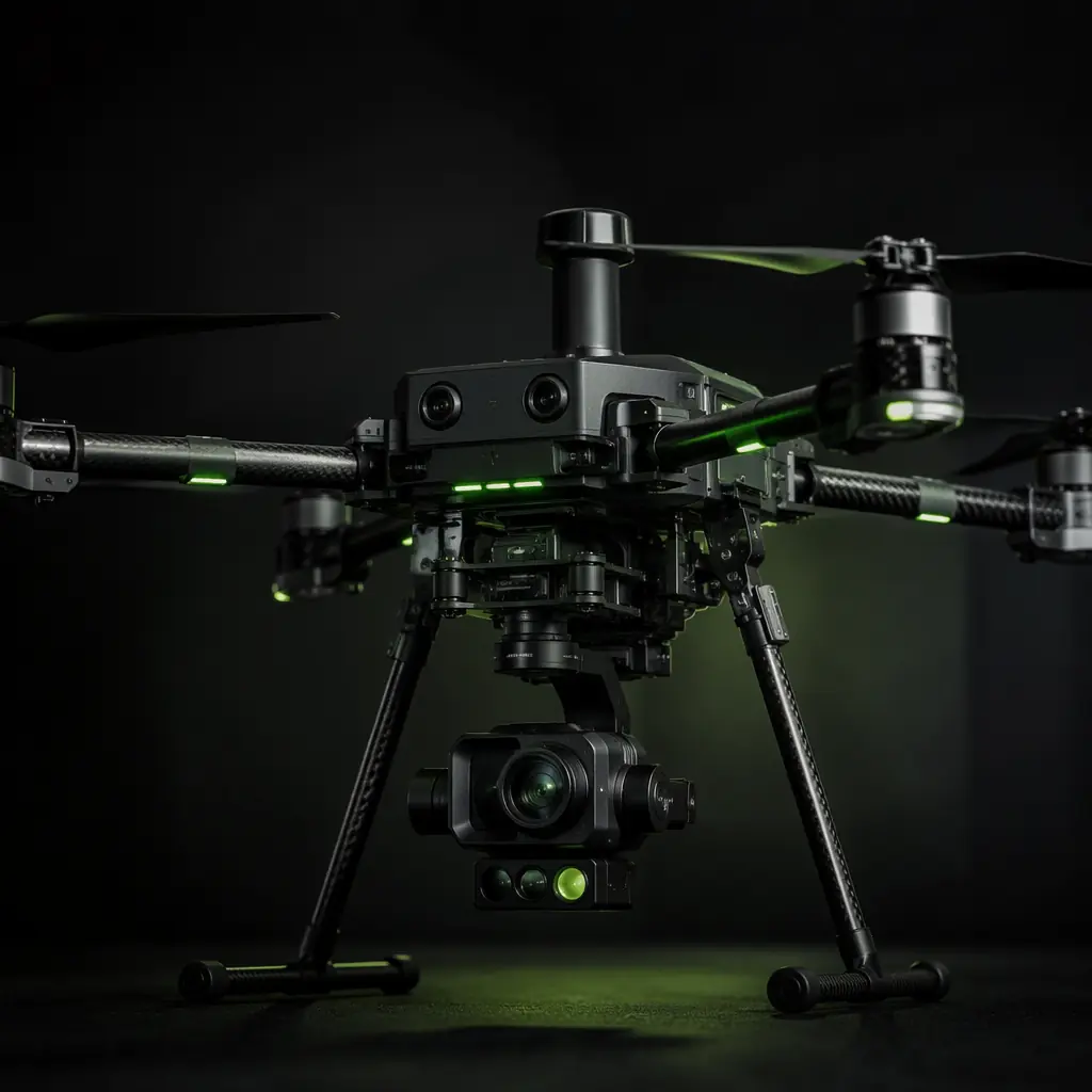
UAV Payload Integration Guide
Sensors, gimbals and release mechanisms, the payload defines the mission.
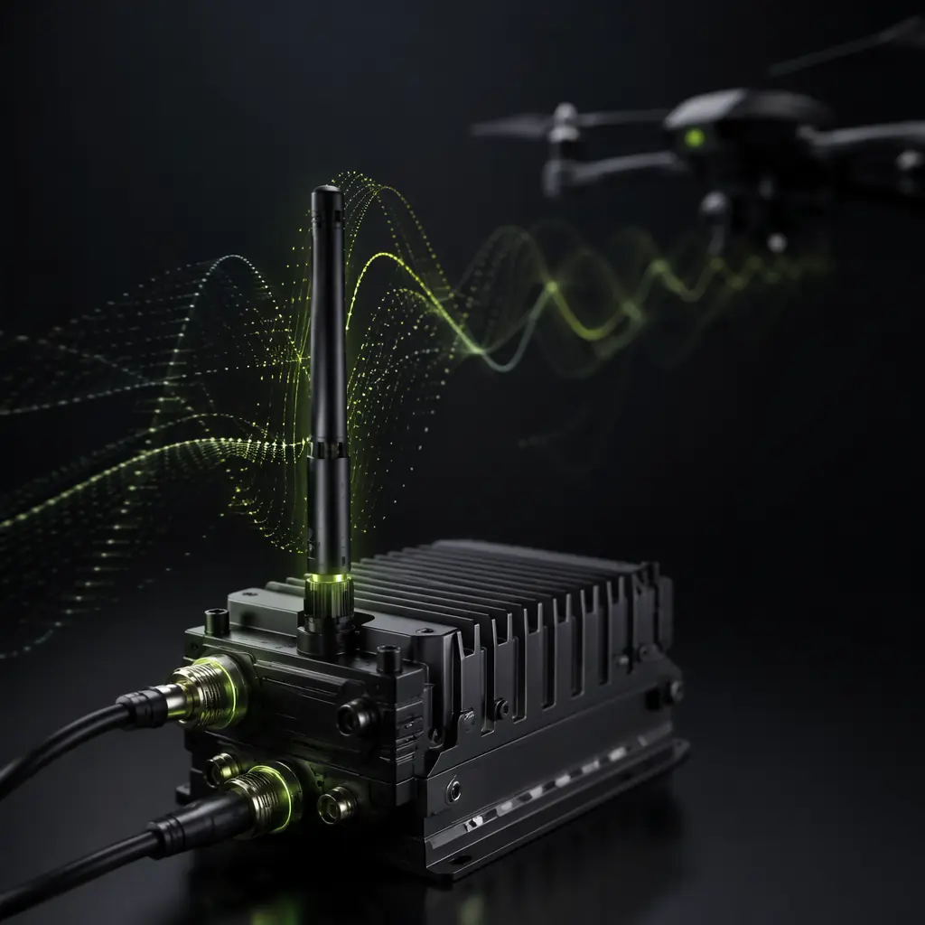
UAV RF Communication Systems
How to coordinate the inspection data pipeline across multiple frequency bands.
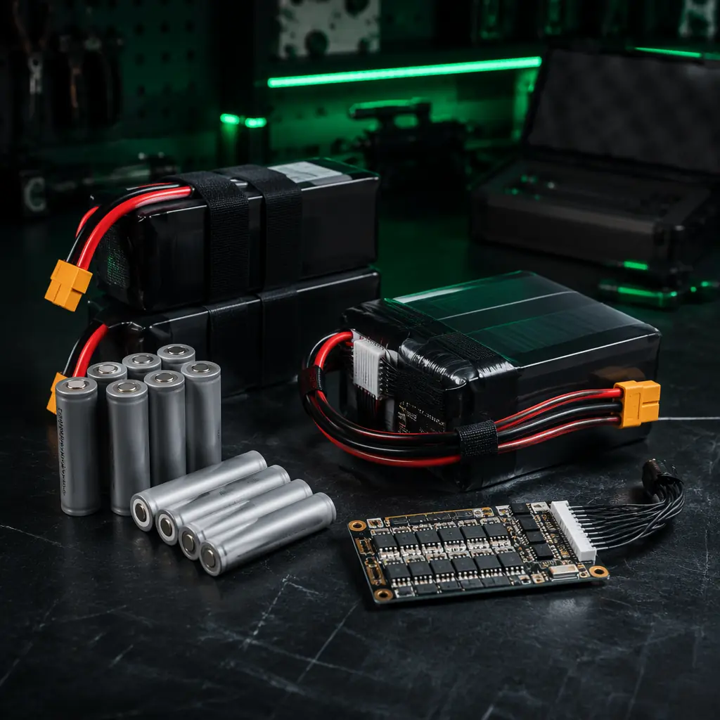
Battery & Power Management
LiPo vs Li-Ion cell selection and BMS architecture for inspection endurance.
UAV Powertrain Matching
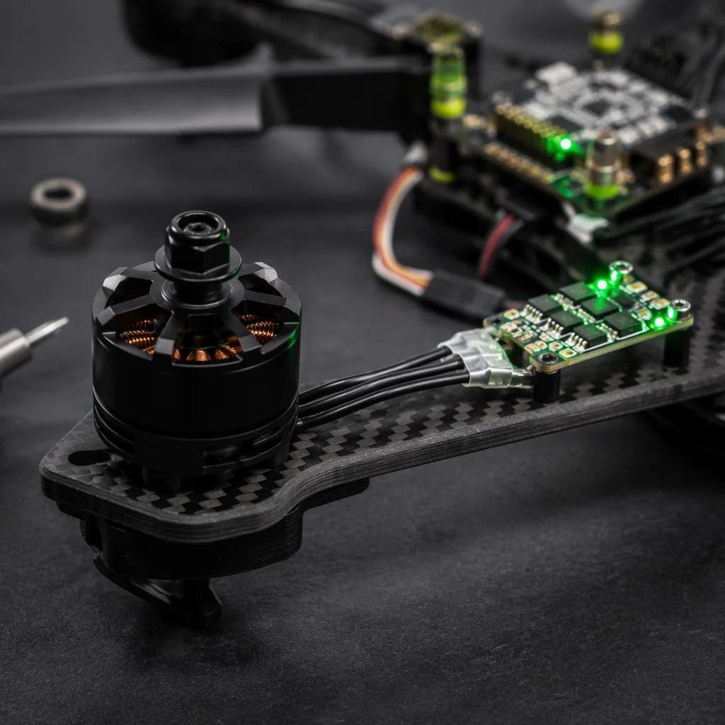
Motor KV, propeller sizing and ESC selection for inspection flight profiles.
Airframe Materials Guide
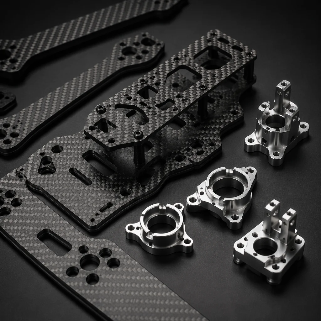
Carbon fiber vs. aluminum vs. G10 for high-temperature inspection environments.