
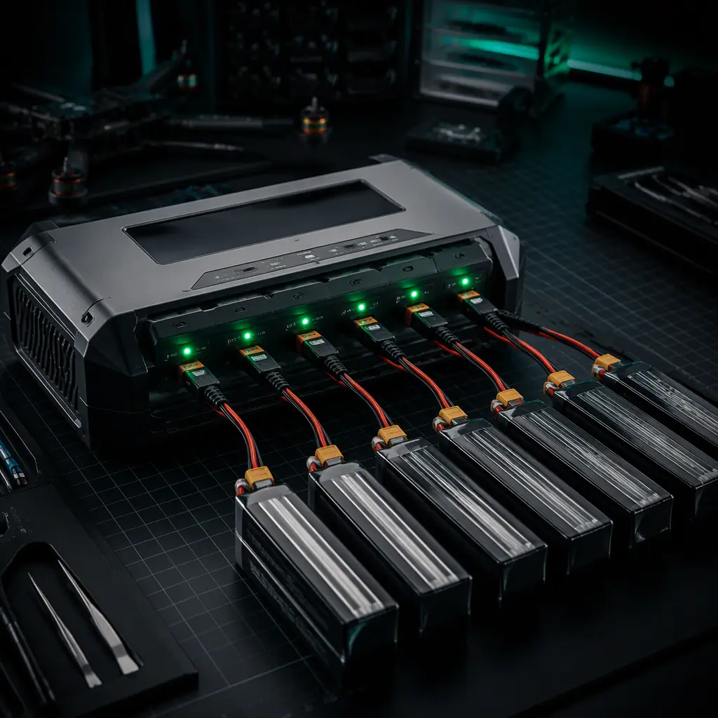
The UAV battery and power management guide explains how to choose the packs; this guide covers the equipment that charges them. A charger cannot fix a bad battery, but a badly chosen charger can destroy a good one. Overcharging a cell by 100 mV on a 6S pack compounds into capacity loss that shows up as sag mid-mission, exactly when the aircraft needs the power most.
The four spec-sheet numbers that decide everything
Every UAV charger datasheet leads with the same four numbers, and they map directly onto your fleet's pack configuration and turnaround requirements:
| Spec | Typical values | What it actually decides |
|---|---|---|
| Cell count (series) | 3S-14S for industrial UAVs, up to 24S for heavy-lift | Which packs the charger can handle at all, the hard compatibility gate |
| Max charge current | 10-40 A per channel (higher on parallel boards) | Charge time per pack and how many sorties the fleet can fly per day |
| Balance current | 0.5-2 A per cell | How quickly cell-to-cell differences are corrected, the pack-lifetime spec |
| Input voltage | 12-48 V DC (many accept 100-240 V AC) | Whether the charger works in a vehicle, a field tent or a lab bench |
Channel count matters just as much as the headline current: a dual-channel charger charging two packs at 15 A each delivers a different fleet outcome than a single-channel unit charging one pack at 30 A, because the battery swap schedule, not raw watts, determines sortie throughput. The field charging and power logistics guide covers the generator and vehicle side; the charger sits between that power source and the packs.
Charge current and C-rate: the math of turnaround time
Charge current is quoted in amperes, but the number that matters for pack health is the C-rate, current divided by pack capacity. A 30 A charge into a 30,000 mAh pack is 1C; the same 30 A into a 15,000 mAh pack is 2C. The consequences are not linear:
- The turnaround math. Charge time is roughly capacity ÷ current plus the balance and taper phases. A 30,000 mAh pack at 1C takes 60-70 minutes wall-to-wall; at 2C it takes 35-45 minutes. For a mapping operation flying five aircraft on overlapping survey lines, that 20-minute difference per pack is the difference between two and three sorties per day per aircraft.
- The cycle-life trade-off. Charging at 2C costs cycle life. Published cell data typically shows a 1C-charged pack retaining 80% capacity after 300-500 cycles, while a 2C-charged equivalent drops to the same threshold 20-40% earlier. The charger current rating is not a permission to use it. It is a ceiling, and the fleet's charge policy should normally stay at or below 1C for LiPo and 0.5C for Li-Ion.
- Current vs voltage taper. A LiPo charges in constant-current (CC) mode until it reaches 4.2 V/cell, then constant-voltage (CV) taper where current decays as the cell fills. The charger's advertised current applies to the CC phase; the CV phase adds 15-25 minutes regardless of charger size. Chargers with a well-implemented taper terminate at the right cutoff instead of trickling forever.
The right question when comparing chargers is not "how many amps" but "how many packs can I turn around per hour at 1C, with correct termination, without exceeding the input power available". The logistics and delivery components guide shows how that pack-turnaround rate feeds the daily mission plan for a delivery fleet.
 Balance leads
Balance current: the spec most buyers ignore
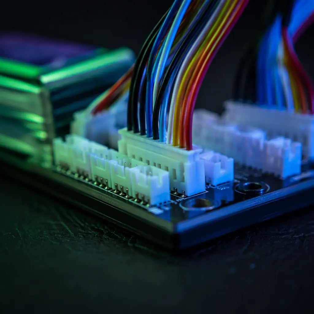
Charge current gets the marketing attention; balance current quietly decides how long packs live. Cells in a pack never age identically, the cell nearest the discharge connector runs warmer and degrades faster, so after every cycle the pack arrives at the charger with small voltage differences between cells. The balance circuit corrects them, and its speed is the balance current:
- Fast balancing is protective. A charger with 1-2 A balance current per cell can equalize a pack with a 30 mV spread in a single charge session. A 0.5 A balancer on the same pack may take two or three sessions. And in the meantime the strongest cell keeps getting pushed to its limit while the weakest lags, accelerating the divergence.
- Balance leads are the weak link. The thin balance wires (28-30 AWG typical) carry the balancing current and the voltage sensing. A damaged balance lead produces false voltage readings that make the charger overcharge a cell; the connectors, wiring and power distribution guide covers the connector quality and strain-relief decisions that keep balance circuits reliable over hundreds of plug cycles.
- Storage balancing. A charger that balances during storage-charge mode (see below) keeps packs at equalized 3.80-3.85 V/cell, which measurably reduces self-discharge spread between cycles. This is why a charger with good balance current pays for itself in pack longevity, not in charge speed.
Smart chargers and battery communication
Industrial UAV packs increasingly carry their own intelligence, and the charger must speak it:
- Balance-lead sensing. The baseline smart feature: the charger reads each cell voltage through the balance lead and terminates per-cell at the correct cutoff instead of trusting a single pack-level voltage. Any charger below this feature set should not be in a commercial fleet.
- Data-bus packs. Higher-end packs embed a fuel gauge or BMS that reports via SMBus, I2C or CAN. A compatible charger reads state of charge, cell temperatures, cycle count and charge history, and can refuse to charge a pack flagged with a fault, a genuine safety feature that a dumb charger cannot provide.
- Temperature-aware charging. Charging a cold pack (below 10 °C for LiPo) at full current risks lithium plating; a charger with a temperature input or a data-bus temperature report derates current accordingly. In winter field operations this is the difference between packs that survive the season and packs that puff by spring.
- Storage and cycle modes. Storage mode charges or discharges to 3.80-3.85 V/cell. The voltage at which LiPo calendar aging is slowest. A fleet that charges packs to 4.2 V and leaves them for a week is losing capacity that a storage-mode routine would preserve.
The payload power budgeting guide covers the same communication and protection thinking on the aircraft side; the charger is the mirror image of the onboard power system, and the two should be specified by the same engineer.
 Parallel charging
Parallel charging boards: when they help and the rules
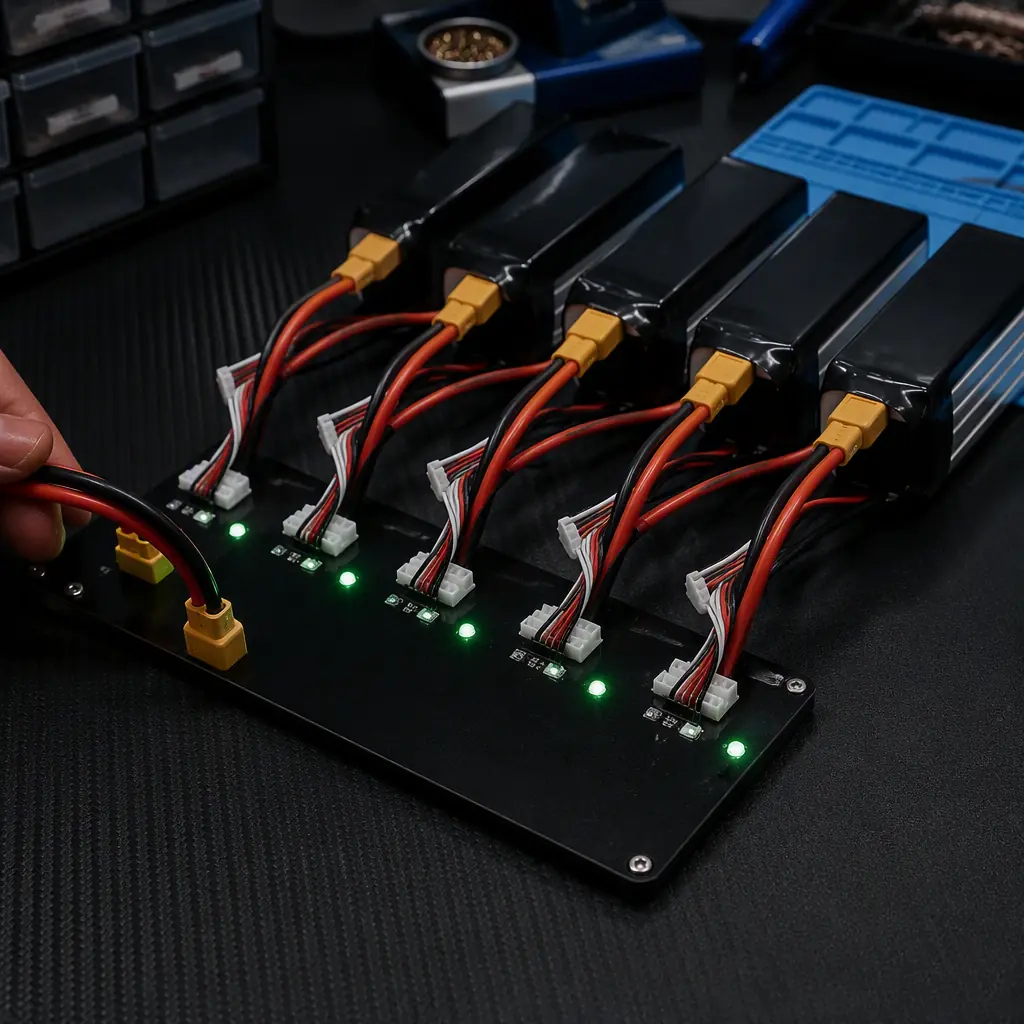
A parallel board lets one high-current charger charge several packs at once, multiplying throughput without buying multiple chargers. It also concentrates every failure mode into one place:
- The 0.1 V rule is non-negotiable. Packs connected to the same parallel bus must be within 0.1 V per cell of each other before connecting. A 3.8 V/cell pack connected beside a 3.9 V/cell pack on a 6S board creates an equalization surge through the balance leads that can exceed their rating. The battery and power management guide explains the parallel charging rules in detail; the charger selection consequence is that the charger must have a per-channel current ceiling low enough to protect the board's fuse and wiring.
- Board quality shows in the copper. A parallel board's current path is its bus bars and solder joints. A board rated for 40 A that uses thin traces will heat, and heat in a charging path is both a failure and a safety hazard. Ask for the board's rated current, the wire gauge it accepts, and whether each port is fused.
- Matching packs only. Parallel charging assumes packs of identical capacity, cell count and chemistry, ideally from the same production batch. Mixing a 30,000 mAh pack with a 20,000 mAh pack on one board charges the smaller pack at a higher C-rate than intended.
For fleets, the alternative to bigger parallel boards is more channels: a multi-channel charger per pack, or a charging bay where each pack has its own port and its own charge profile. The trade-off is capital cost against the operational cost of sorting and matching packs.
Fleet charging bays: the physical design nobody specs
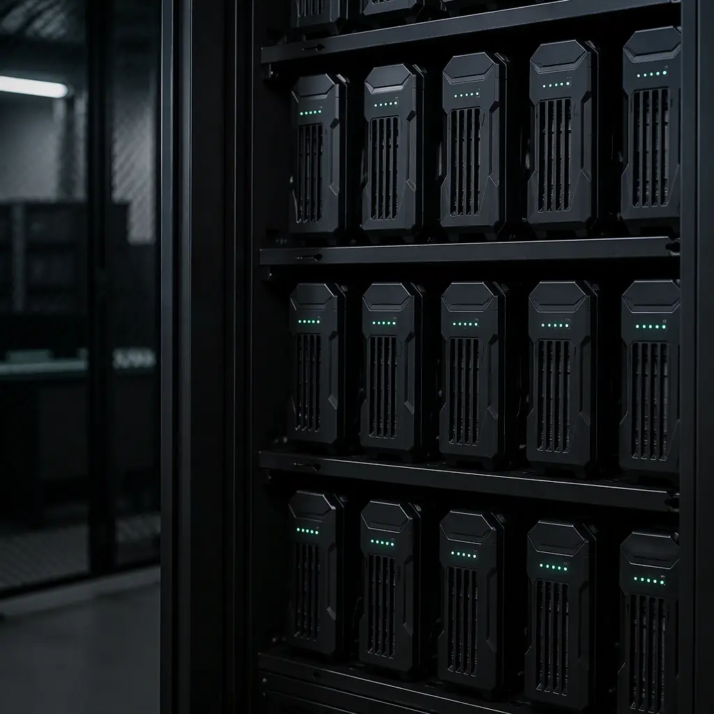
Once a fleet passes a handful of packs, the charger selection becomes a charging-station design problem. The physical decisions matter as much as the electrical ones:
- Connector wear. A pack that is plugged and unplugged three times a day accumulates 1,000+ connector cycles a year. The charging bay should use the same connector family as the aircraft, with strain relief and a mating cycle rating that matches the fleet's usage. The connectors and wiring guide covers connector cycle life and contact resistance in detail.
- Airflow and spacing. Charging generates heat, in the charger, in the balance circuits and in the packs themselves. A bay that crams packs side by side with no airflow raises pack temperature during the charge, which both slows the taper and ages the cells. Each pack slot should have clear air path and the bay should be in a ventilated area, not a sealed case.
- Fire containment. The realistic failure mode for a damaged pack is thermal runaway during charge. Charging bays for professional fleets are increasingly built from fire-rated materials, with each pack slot sized to contain a venting cell, and a smoke alarm or thermal sensor in the bay. This is an insurance conversation as much as an engineering one.
- Grounding and transients. A bay fed from a vehicle or generator shares the ground plane with the aircraft's charging input; ground loops can feed transients into the charger. The grounding and isolation practice from the field charging guide applies at the bay level too.
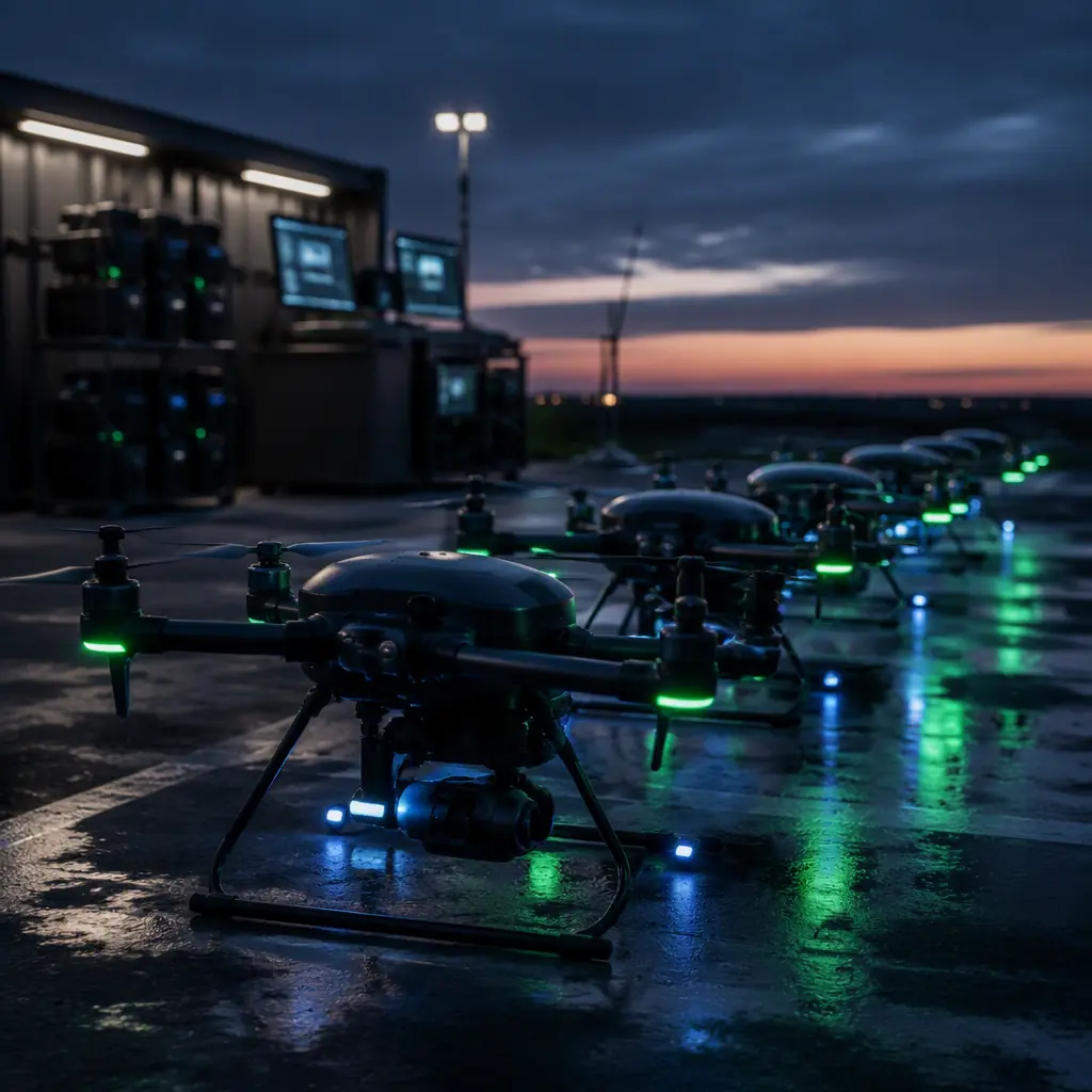
 Fleet charging bay
Charging safety and thermal management
Battery fires during charging are the most common catastrophic failure in UAV operations, and the charger is the piece of equipment that can prevent or trigger them:
- Correct termination is a safety feature. Overcharge is the classic ignition path: a charger that terminates at the wrong voltage, or a balancer that cannot keep up, pushes a cell past 4.25 V where LiPo chemistry becomes unstable. Verified per-cell termination and a charger that faults instead of guessing are the first line of defense.
- Charge-site temperature. The charger itself has an operating temperature range, usually 0-40 °C, and its output derates outside it. A charger baking in a closed vehicle in summer will either throttle, slowing the fleet, or run hot enough to shorten its own life. The thermal management for UAV electronics guide covers the same derating logic for onboard electronics.
- Inspection protocol. Packs should be inspected before every charge: swollen cells, damaged balance leads, or a pack that arrives warm from a hard flight should be quarantined, not plugged in. The charger cannot see a swollen cell; the operator protocol is the sensor.
Storage charging and battery asset life
Chargers quietly govern the two biggest drivers of fleet battery cost: charge C-rate and storage voltage. The spares and lifecycle planning guide shows how pack replacement dominates the TCO model; the charger is the tool that extends the interval:
- Storage voltage discipline. A pack stored at 4.2 V/cell loses capacity measurably faster than one stored at 3.80-3.85 V/cell. Calendar aging accelerates steeply above 4.0 V. A charger with automatic storage mode, or a bay that cycles packs to storage voltage after the day's flying, is a fleet-management feature, not a convenience.
- Cycle tracking. Chargers with data logging record charge cycles per pack, which feeds the replacement schedule and the warranty conversation with the pack supplier. Packs are consumables with a documented cycle life; the charger is the instrument that counts the cycles.
- Fleet integration. The fleet management components guide covers the software side; a charger that reports charge events into the fleet log ties battery health data to mission data, which is where the pattern, "pack 4 always sags after charge 60", becomes visible.
Charger procurement checklist
- Compatibility. Cell count range covers the fleet's packs (6S-14S for most industrial platforms) with headroom for the next pack generation.
- Current policy. Charge current sufficient for the fleet's turnaround target at ≤1C for LiPo and ≤0.5C for Li-Ion; per-channel current ceiling that protects the parallel board and its fuses.
- Balance current. ≥1 A per cell for packs above 10,000 mAh; verify the balancer's behavior across the full cell count.
- Input flexibility. DC input range that accepts the vehicle or generator voltage planned in the field power design, plus AC input for the lab.
- Smart features. Per-cell termination, storage mode, temperature input or data-bus support, and charge logging, specify the data format the fleet software expects.
- Bay hardware. Connector family matched to the aircraft with rated cycle life, airflow, fire containment and grounding per the bay design.
- Documentation. A charger test report with the RFQ: termination accuracy at the fleet's cell count and current, balance behavior, and derating curve.
The bottom line: the charger is the most under-specified piece of equipment in a UAV fleet. Match the cell count, size the current to a deliberate C-rate policy, pay attention to balance current and termination accuracy, design the bay for airflow and fire containment, and use storage mode as a battery-life tool. EMS Drone specifies complete power chains, batteries, chargers, charging bays and the onboard power system, so the ground equipment and the aircraft agree on voltage, current and communication. Send your pack configuration and sortie profile, and we will respond with the charger specification, the bay layout and the charge-policy RFQ clauses.
Explore ESC & Power Systems Back to Blog
Continue Reading
Battery & Power Management
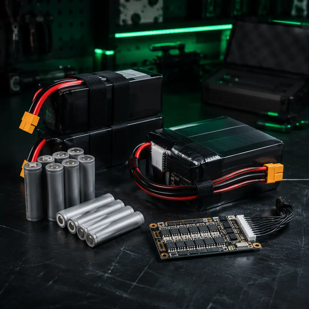
The LiPo vs Li-Ion trade-offs and parallel charging rules the charger must serve.
Field Charging & Power Logistics
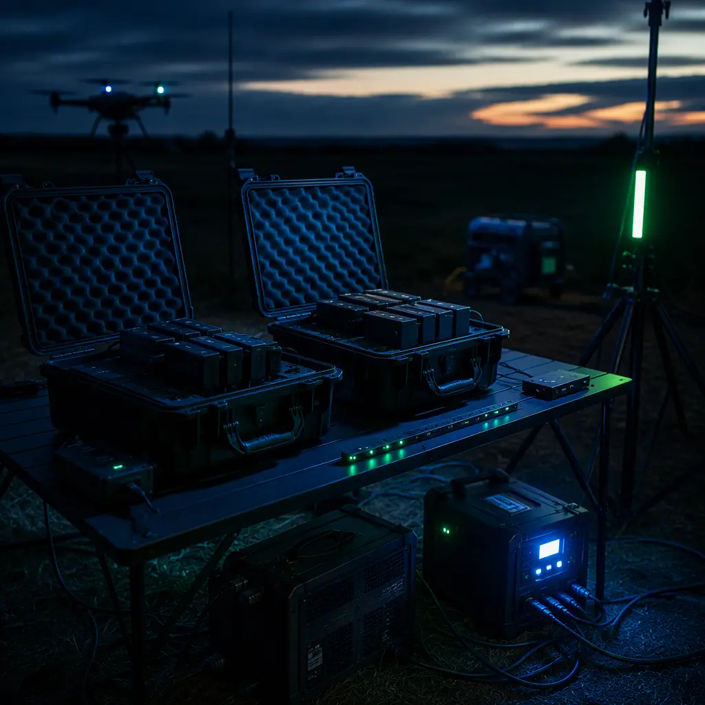
Generators, solar and vehicle DC, the power sources the charger plugs into.
Spares & Lifecycle Planning
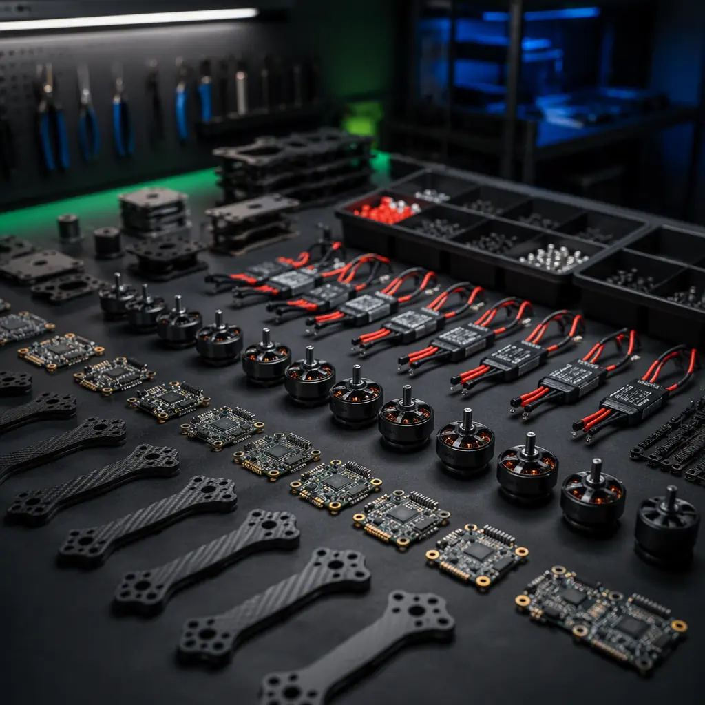
Why pack replacement dominates the fleet TCO model the charger protects.
Connectors & Wiring
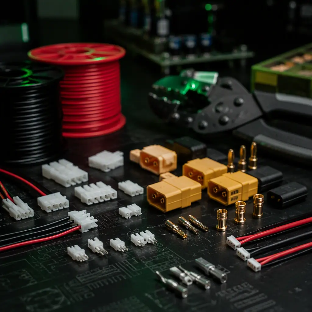
The connector cycle life and contact resistance that decide bay reliability.
Fleet Management Components
Where charge-cycle data feeds the fleet health log.