

Fleet management is the operational layer between the aircraft and the maintenance program. The single-aircraft stack covered in the ground control station hardware guide ends when the pilot lands; the fleet stack begins when the airframe is back on the ground and the next mission needs to know its state. The components that produce that state fall into five groups, and each group maps to a specific procurement decision.
The fleet telemetry layer: reporting beyond the radio link
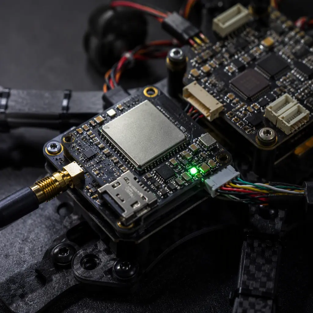
The single-aircraft telemetry link closes when the aircraft lands or leaves range. A fleet operation needs a second, independent reporting path that works on the ground, in the hangar and across the city — and that path is usually a cellular or satellite IoT module rather than the control link. The UAV RF communication systems guide covers the mission link; the fleet telemetry module is a separate radio with different economics: it transmits short status messages — position, battery state, flight hours, health flags — at intervals measured in seconds or minutes, over a network that is already deployed.
The cellular IoT option. A 4G/LTE Cat-M or NB-IoT module reports from anywhere with coverage. Cat-M (LTE-M) is the practical choice for UAV fleet telemetry: it supports mobility and voice-grade latency, works while the aircraft is moving, and its power draw is compatible with a small backup cell or the main battery bus. NB-IoT is cheaper and lower-power but not designed for moving nodes — it suits fixed assets like charging stations more than airframes. The spec numbers: a Cat-M module at a 5-minute report interval consumes roughly 10–30 mAh per day in normal operation, which a dedicated 500 mAh backup cell supports for weeks.
The satellite option. For fleets operating beyond cellular coverage — long-range inspection programs, offshore logistics, agricultural operations in remote regions — a satellite IoT transceiver (Iridium-style short-burst or L-band) reports position and health from anywhere. The economics are per-message: a short-burst satellite report costs more per byte than cellular by orders of magnitude, so the fleet spec should define the report budget: which events are worth a satellite message (lost cellular contact, emergency beacon, mission-complete confirmation) and which wait for the next cellular window.
Integration into the aircraft. The fleet module needs a power input, an antenna with a clear sky view, and a data interface to the flight controller or companion computer. The integration decision belongs in the edge AI and onboard computing guide's architecture conversation: the companion computer can pre-process the status messages before transmission, so the fleet module reports derived health state rather than raw logs. The connectors and wiring guide covers the physical layer — a fleet module is one more antenna and one more power tap, and its wiring discipline is the same as the mission radio's.
 Concept illustration
Battery lifecycle tracking: the fleet's most expensive consumable
In a multi-aircraft operation, batteries are simultaneously the most expensive consumable and the component with the clearest failure curve. The UAV battery and power management guide covers the chemistry selection; the fleet layer adds the tracking infrastructure that turns a pile of identical packs into a managed inventory with known state. Three mechanisms do the work:
Serialization. Every pack gets a unique identity — a printed label, an RFID tag, or an electronic ID in the battery's management system. The identity is the key to every other tracking mechanism: without it, a flight log cannot be attributed to a physical pack.
Cycle counting. The pack's charge/discharge cycles are recorded — by the charger, by a battery management system (BMS) in the pack, or by the fleet software reading the pack's telemetry. The procurement-relevant spec is the cycle budget: a typical 6S LiPo pack in fleet service is retired at 200–400 cycles depending on discharge depth, and a Li-Ion pack at 400–800, numbers the power management guide explains in depth. The fleet system should flag packs approaching the budget before a flight, not after a failure.
State-of-health estimation. Beyond cycle count, the useful signal is internal resistance growth and capacity fade, which the charger or BMS can measure. A pack whose internal resistance has risen 30% delivers less peak current — visible as voltage sag under load — and should be downgraded to low-current missions or retired. The fleet spec should name the measurement: internal resistance at a defined SOC, capacity at a defined discharge rate, or both.
The ground infrastructure that supports battery tracking is covered in the charging section below; the procurement point is that battery lifecycle hardware — serialization, BMS with telemetry, charger with logging — must be specified as part of the aircraft order, because retrofitting cycle tracking onto packs after delivery is far more expensive than specifying it at the RFQ stage.
Health monitoring: the sensors that log what the pilot does not see
Fleet maintenance decisions are only as good as the data behind them. The health monitoring layer adds sensors and logging that capture the aircraft's condition across its life, independent of any single flight's telemetry:
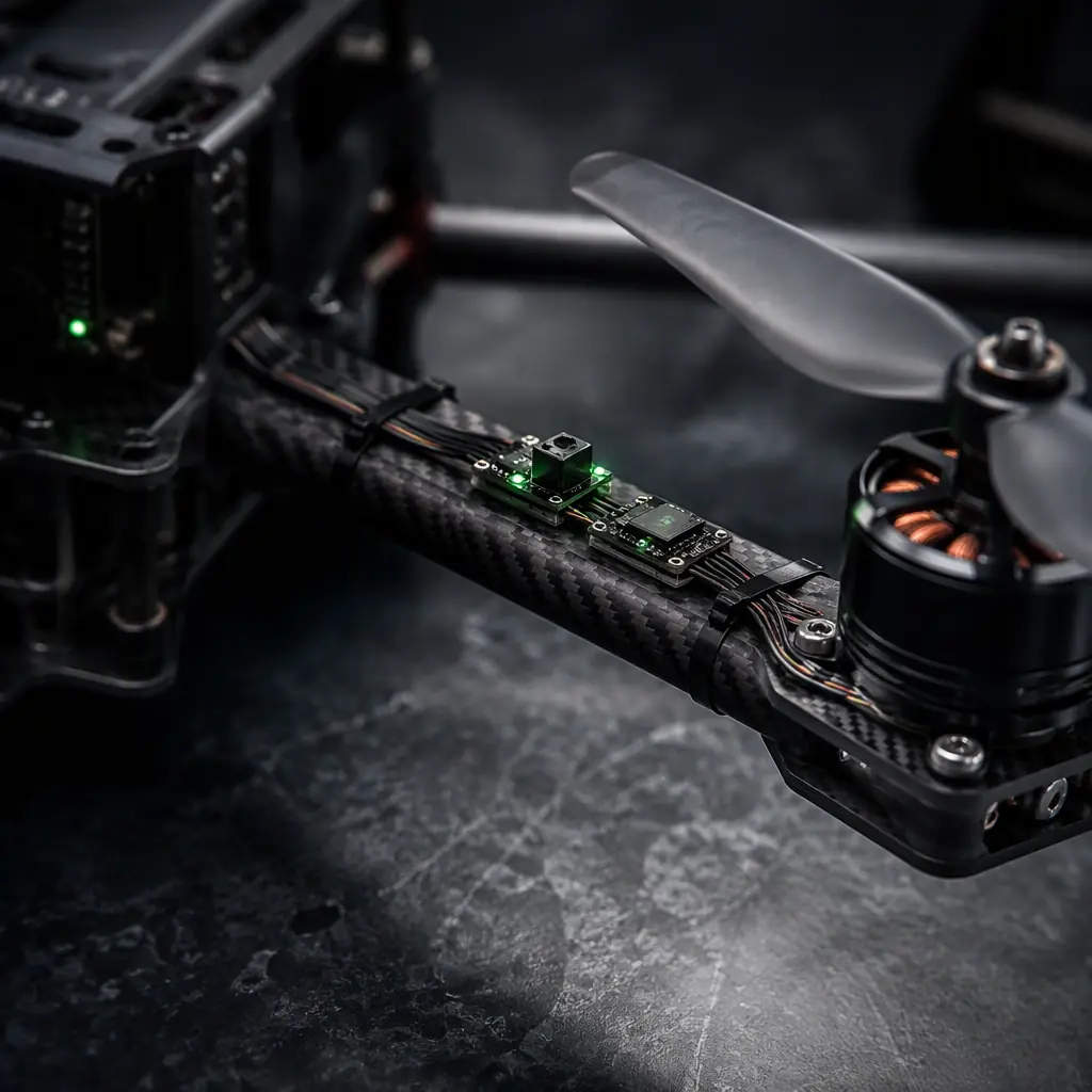
Vibration sensing. An accelerometer on the airframe or the motor mounts logs vibration spectra per flight. The diagnostic value is specific: a bearing degrading on motor 3 produces a characteristic vibration signature — rising amplitude at the motor's rotation frequency and its harmonics — long before it fails visibly. The fleet system's job is to compare each flight's vibration profile to the airframe's baseline and flag deviations. The procurement spec is the sensor's bandwidth (a 1–10 kHz accelerometer captures motor-order vibrations on most multirotors) and the logging rate.
Temperature logging. The thermal management guide explains why ESC and motor temperatures are the primary health signal for propulsion; the fleet layer records them per flight and trends them across flights. An ESC whose peak temperature climbs 10°C over 50 flights — at constant load — is telling the maintenance program something a single flight log cannot.
Flight-hours and cycle counters. The flight controller or companion computer maintains the airframe's flight-hour total and the per-component cycle counts (motor starts, gimbal movements, payload actuations). These numbers drive the inspection schedule: an airframe at 100 flight hours, or a propulsion group at 500 motor starts, enters a defined inspection checklist. The sensor fusion and redundant navigation guide covers the IMU and navigation sensor layer that most health logging reuses — the same accelerometers that feed the flight controller also feed the fleet's vibration analysis, if the data path is specified.
The health data has a home: the fleet software platform that aggregates logs, computes baselines and generates maintenance work orders. The edge AI guide covers the onboard compute that pre-processes this data; the fleet platform is its ground counterpart, and the interface between them — the log format, the report interval, the alert thresholds — should be specified at procurement time, not improvised after the first 1,000 flight hours.
 Concept illustration
Charging and storage infrastructure: the ground side of the fleet
A fleet operation is a ground operation: aircraft spend most of their life on the ground, and the ground infrastructure determines how many missions per day the fleet can fly. The logistics and delivery components guide covers the mission-level ground stack; the fleet layer adds three infrastructure components:
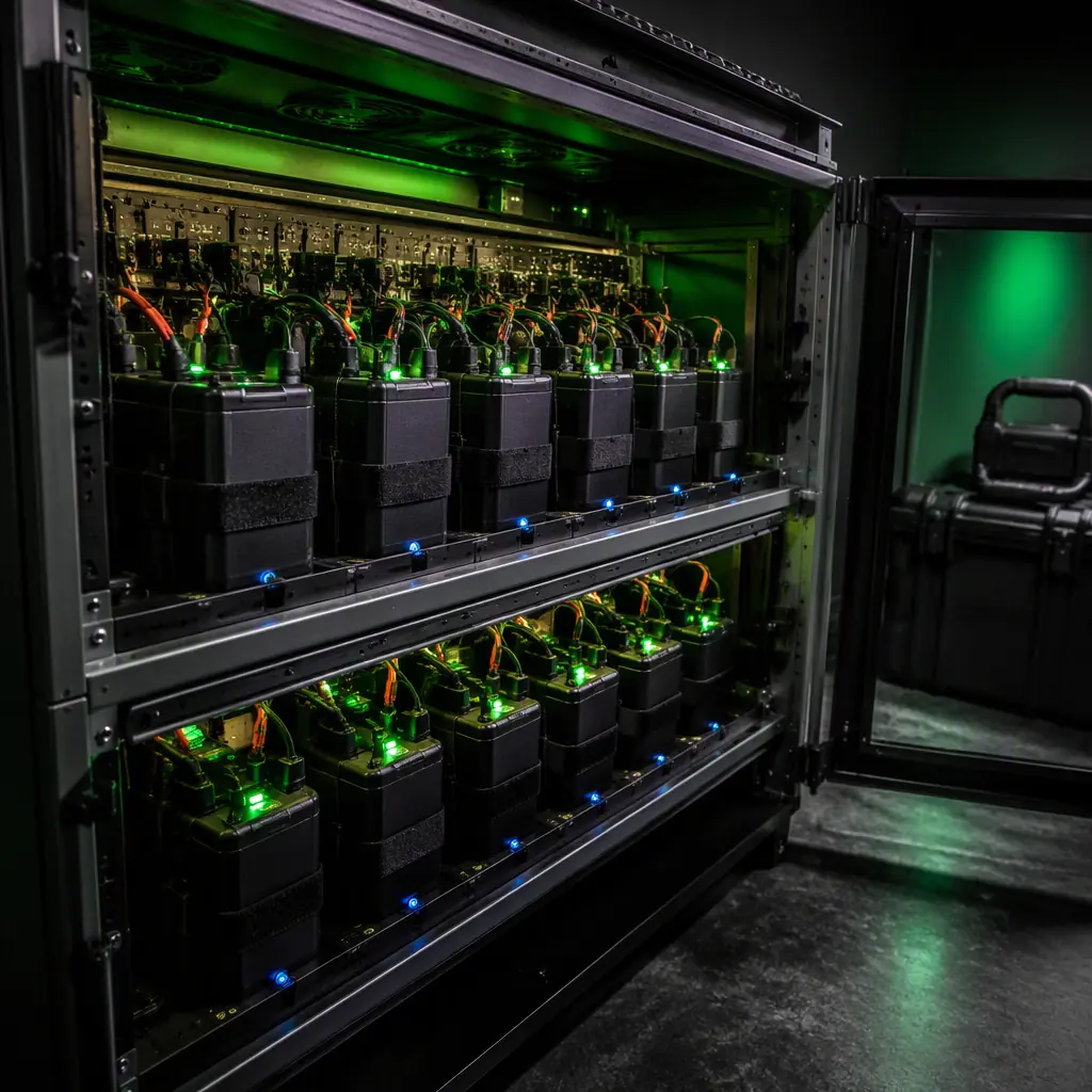
Parallel charging racks. A battery rotation system — one pack flying, one cooling, one charging — keeps the fleet flying continuously. The rack's spec is the charge current per channel (a 6S 12,000 mAh pack charges at 1C in roughly 60 minutes; the rack's throughput, not the aircraft count, sets the fleet's mission rate), the balance accuracy, and the logging interface that feeds the cycle-counting system.
Storage and containment. Batteries in storage, transport and charging need fire-containment and a defined storage SOC (typically 40–60% for long-term LiPo storage). The containment hardware is a procurement line item for fleet operations — a charging rack with per-channel temperature monitoring and a fire-containment enclosure is the difference between a battery event and a hangar fire. The safety and redundancy systems guide covers the aircraft-side failure protections; the ground side deserves the same rigor.
Ground power and connectivity. The charging infrastructure needs power distribution sized for the fleet (a 10-aircraft fleet with 6S packs charging simultaneously draws several kilowatts) and network connectivity so chargers report cycle data to the fleet platform. The wiring and connector discipline from the connectors and power distribution guide applies on the ground side as much as in the air — ground infrastructure is where intermittent connections cause the fleet data gaps that defeat the entire tracking system.
 Concept illustration
Spares management and the obsolescence loop
A fleet makes the spares question quantitative: with N airframes flying M hours per week, the consumption rate of consumables — propellers, batteries, motors, connectors — is a forecastable number, and the inventory follows. The spares calculation belongs in the fleet procurement spec: the obsolescence management guide covers the lifecycle side (which components go EOL and when); the fleet layer adds the stock-level side (how many spares to hold for a given fleet size and utilization).
The connection is direct: a fleet of twenty airframes flying the same motor has a known motor-failure distribution, and the fleet platform's maintenance logs produce the empirical failure rate that refines the spares forecast. A fleet program that procures its initial spares package from the supplier's data — not from a guess — starts with the right inventory. The same fleet data feeds the procurement loop for the next aircraft order: airframe utilization, payload wear and the component failure history become the input to the supplier evaluation checklist and the build vs buy decision for the fleet's next generation.
Fleet software integration: where the components report
Every component described above produces data; the fleet software platform consumes it. The procurement-relevant question is not which platform to buy — it is which data interfaces the aircraft hardware must expose for any platform to consume:
The telemetry interface. The flight controller and the fleet module must expose position, battery state and health flags in a documented format — MAVLink telemetry, a JSON REST feed from the companion computer, or a vendor API. The communication protocols guide covers the onboard buses (CAN, DShot, SBUS, CRSF) that carry the raw data; the fleet platform consumes it one layer up.
The maintenance interface. The aircraft's log storage — the vibration spectra, the temperature histories, the cycle counters — must be exportable in a documented format with timestamps the platform can reconcile against flight logs.
The identity interface. The fleet module and the battery BMS must report serialized identities that the platform can attribute data to. An aircraft whose telemetry is not attributable to a serial number is invisible to the fleet system.
The specification discipline is the same one the ground control station guide applies to mission hardware: the data interfaces are contract items, not implementation details. A fleet aircraft whose hardware exposes clean, documented interfaces integrates with any fleet platform; one whose data is locked in a vendor format integrates with none.
The RFQ checklist: 11 line items for fleet-ready aircraft
The following line items make a fleet aircraft orderable. They apply to the aircraft hardware itself, and each item names the evidence the supplier should provide.
1. Fleet telemetry module. The aircraft includes a cellular IoT or satellite reporting path independent of the mission link, with the report interval and message content specified. Verification: module datasheet and integration drawing.
2. Telemetry data interface. Position, battery state and health flags are exposed in a documented format (MAVLink, REST or vendor API) with the update rate stated. Verification: interface documentation and a sample telemetry payload.
3. Battery serialization. Every pack carries a unique identity readable by the fleet system. Verification: serialization label or electronic ID implementation.
4. Battery state-of-health reporting. The pack or charger reports cycle count, internal resistance and capacity, with the measurement method documented. Verification: sample SOH report from a delivered pack.
5. Health monitoring sensors. The aircraft carries vibration and temperature logging on the propulsion group, with the sensor bandwidth and logging rate stated. Verification: sensor spec and a sample flight log.
6. Flight-hours and cycle counters. The airframe maintains flight-hour and component-cycle totals accessible to the fleet platform. Verification: counter access method and reset policy.
7. Charging interface. The packs charge on the fleet's parallel rack with the charge profile, connector and balance interface documented. Verification: charge connector spec and profile data.
8. Ground infrastructure fit. The aircraft's storage and transport configuration is compatible with the fleet's containment and racking hardware. Verification: dimensional drawings and storage SOC guidance.
9. Spares consumption data. The supplier provides initial consumption-rate estimates for consumables (propellers, motors, batteries) based on fleet-scale utilization. Verification: consumption data sheet with confidence basis.
10. Maintenance documentation. Inspection intervals, service procedures and the log-review workflow are documented for fleet maintenance staff. Verification: maintenance manual and inspection checklist.
11. Traceability. Each airframe's logs, telemetry and maintenance records remain attributable to its serial number for the platform's retention period. Verification: traceability policy and record sample.
The fleet stack connects to the rest of the procurement picture: the battery and power management guide for the packs, the ground control station guide for the mission ground layer, and the obsolescence management guide for the lifecycle loop that keeps a fleet flying past its first year.
Explore custom engineering Back to Blog
Continue Reading
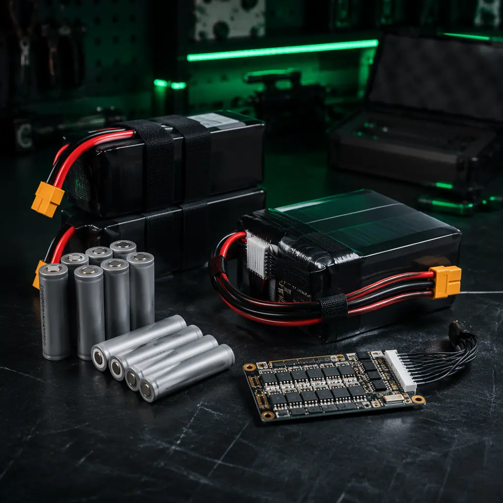
UAV Battery and Power Management
The chemistry and pack-design layer behind the fleet's most expensive consumable.
UAV Ground Control Station Hardware
The mission ground stack that the fleet layer extends with tracking and maintenance infrastructure.
UAV Edge AI & Onboard Computing
The companion computers that pre-process fleet telemetry and health data before transmission.
Thermal Management for UAV Electronics
The temperature data that powers propulsion health trending across a fleet.

UAV Component Obsolescence Management
The lifecycle loop that keeps a fleet's spares and BOM flying past year one.