
The propulsion system gets a power budget; the payload gets a Y-cable. Every integration engineer has seen the pattern: the aircraft was specified around the motors, the ESC ratings and the battery C-rate, and the payload stack, thermal camera, RTK receiver, companion computer, gimbal, was treated as a collection of data interfaces rather than a power load with its own transient behavior. The result is a class of failures that are intermittent, temperature-dependent and maddeningly hard to reproduce on the bench: a camera that resets when the gimbal starts moving, a GNSS fix that degrades when the telemetry radio transmits, an ADC channel that reads 2% high in the afternoon. All of them are power problems, and all of them are preventable with a budgeting exercise that takes an afternoon. This guide walks through it end to end, and it builds directly on the UAV battery and power management guide (which sizes the main pack) and the connectors and power distribution guide (which covers the PDB and wiring that carries the payload rails).
The five ways payload power fails in the field
Before the budget math, it is worth naming the failure modes, because each one maps to a specific design decision later in this guide. Fielded industrial UAVs fail in five recurring patterns:
- Brownout under load. The payload stack draws more than the distribution rail can deliver during a transient: typically the moment a gimbal or servo starts moving or a camera shutter mechanism engages. The rail collapses, the companion computer or flight controller resets, and the aircraft enters a boot loop in flight. The sensor fusion and redundant navigation guide explains why a mid-flight reset of the navigation stack is not a nuisance but a safety event.
- Switching noise coupling. Every DC-DC converter on the aircraft switches at 300 kHz–2 MHz, and the ripple and radiated noise couple into sensitive payloads, GNSS front ends, image sensors, IMUs, through the shared input rail, the wiring harness or the ground plane. The symptom is a payload that works on the bench with a lab supply and misbehaves in the air.
- Inrush current. Payloads with large input capacitors (gimbals, video transmitters, companion computers) draw a current spike at power-on that can trip the PDB's current limit or fold back the BEC, starving the rest of the aircraft at the worst possible moment, power-on with motors armed.
- Power sequencing failures. When a peripheral powers up before its controller is ready, I2C and SPI buses lock into undefined states, SD cards corrupt, and the payload needs a full power cycle to recover. This is the classic "works 70% of the time" failure.
- Ground loops. When the payload's power return and data return take different paths back to the PDB, the voltage offset between them appears directly in analog measurements. A 50 mV ground offset on a 3.3 V ADC is a 1.5% full-scale error, which is fatal for an atmospheric pressure sensor or a load-cell payload.
Each of these maps to a section below. The common thread: payload power is an engineering subsystem with its own budget, topology and test plan, not an accessory.
Building the payload power budget: a worked example
The budget starts with a table of every payload device, its continuous draw, its peak draw and its rail voltage. A representative industrial inspection stack looks like this:
- RTK GNSS receiver: 1.2 W continuous, 1.5 W peak, clean 5 V rail required.
- Thermal camera: 4.5 W continuous, 6 W peak at shutter calibration, 12 V or 5 V.
- RGB mapping camera: 3 W continuous, 8 W peak during capture burst, 5 V.
- Companion computer (edge AI): 12 W continuous, 18 W peak under load, 5 V at 4 A. The UAV edge AI and onboard computing guide covers the compute side of this load.
- LTE modem: 5 W continuous, 9 W burst during uplink, 5 V.
- Gimbal: 8 W continuous, 15 W peak when slewing, 12 V.
The arithmetic that matters has three numbers. Continuous total (33.7 W in this stack) sizes the average load on the battery. Peak total (57.5 W) sizes the distribution rail and the regulator output capability. Largest single transient (the gimbal's 15 W, or the camera's 8 W burst) sizes the bulk capacitance and the current-limit headroom. The design rule is: the rail must deliver continuous total × 1.25 margin, and peak total must not come within 20% of the PDB's current limit.
The budget also converts directly into flight time. At 33.7 W continuous from a 6S pack (22.2 V nominal), the payload draws 1.52 A; over a 45-minute flight that is 25.5 Wh, roughly 23% of a 6S 5000 mAh pack's 111 Wh. The same payload on a 12S aircraft draws half the current but the same power. This is why the power budget is a mission conversation, not an electronics conversation: every watt of payload power is endurance the operations team has to give up elsewhere, which is exactly the trade framework laid out in the battery sizing guide.
Regulator topology: linear vs buck vs buck-boost, and where each wins
Once the rails are defined, the next decision is how each rail is derived from the pack voltage. Three topologies cover nearly every UAV payload:
- Linear regulators (LDO). Lowest noise, no switching artifacts. The output is the input minus a pass-transistor drop. The cost is efficiency: a 5 V rail derived from a 6S pack at 22.2 V dissipates 77% of the power as heat. An LDO is the right choice for low-current analog rails (a 20 mA IMU reference, an op-amp supply) and for post-regulating a switcher down to a clean final voltage. It is the wrong choice for any rail over a few hundred milliamps.
- Buck (step-down) converters. The workhorse of payload power: 85–95% efficient at 5 V or 12 V from any pack voltage above the rail. The cost is switching noise, ripple of 10–50 mV plus radiated harmonics at the switching frequency and its multiples. A buck needs a properly chosen output filter and careful layout, and its switching frequency should be selected to avoid beating with the payload's data clocks. For an 8–20 V input range, a fixed-frequency buck at 400–500 kHz is a common, well-understood choice.
- Buck-boost converters. Needed when the pack voltage crosses the rail voltage during the flight. A 4S pack at 14.8 V nominal sags to 13.2 V under load, so a 12 V payload rail needs a converter that can pass through the crossover without a dropout glitch. Buck-boost is also the standard for 5 V rails on 3S aircraft. Efficiency is a few points lower than a pure buck, and noise behavior is generally worse, so it belongs only where the voltage range genuinely requires it.
Isolated DC-DC converters deserve a separate mention: when a payload must be galvanically isolated from the aircraft power (RS-485 or RS-422 links, video transmitters, high-current servo rails that could dump noise into the flight controller), an isolated module breaks the ground path at the converter, which is often simpler and more reliable than trying to filter the loop away. The wiring and power distribution guide covers the conductor side, the AWG sizing and PDB copper weight that carry these rails without unacceptable drop.
 Concept illustration
Filtering and noise: protecting the sensitive rails
The noise problem is not the converter's ripple at its own frequency. It is what that ripple does to the payload's most sensitive inputs. The coupling paths are three: conducted (switching current injected into the shared input rail, seen by every device on that rail), radiated (the loop formed by the converter's wiring radiating into nearby antenna feeds and unshielded sensor cables), and ground bounce (switching current returning through the ground plane, shifting the local ground reference under the sensor).
The GNSS case is the most instructive. A GNSS receiver's L1 front end at 1575.42 MHz is sensitive to interferers at that frequency and near it; a buck converter switching at 1.5 MHz does not hit L1 directly, but its harmonics and the intermodulation products with other clocks can land inside the passband and desensitize the receiver by 3–10 dB, the difference between a reliable RTK fix and one that drops in tree cover. The practical countermeasures, in order of effectiveness: keep switchers and their wiring at least 20 cm from the GNSS antenna feed; post-regulate the receiver's rail with an LDO so the receiver never sees switching ripple; add a pi filter (series inductor with a capacitor on each side) or ferrite bead on the receiver's input; and use a filtered, grounded antenna feed. The GNSS anti-jamming and spoofing guide covers the RF-interference side of the same story, and the EMC/EMI design guide is the full treatment of radiated and conducted compliance.
Camera and IMU rails are the second priority. Image sensors require ripple under roughly 10 mV on their analog rails, or fixed-pattern noise appears in the image; IMUs can alias switching ripple into gyro bias drift. The fix is the same architecture: switcher for efficiency, then an LDO or LC filter on the final rail, with the filter placed within a few centimeters of the sensor. Filtering at the PDB and then running an unfiltered wire to the camera is filtering the wrong place. The camera and gimbal selection guide covers the sensor-side requirements that drive these rail specifications.
 Concept illustration
Power sequencing and inrush: the hidden reset loop
The most frustrating payload faults are sequencing faults, because the hardware is fine, the order of events is wrong. Two mechanisms dominate. Inrush: a gimbal with 2,000 µF of input capacitance presents a near-short at power-on; if the PDB's current limit or the BEC's fold-back engages, the rail collapses, the companion computer browns out and resets, and the camera re-initializes with a 30-second boot delay. In a 45-minute mission that is a significant fraction of the sortie burned on the ground. Sequencing: when a peripheral powers up before its controller's firmware is ready, I2C and SPI slaves can latch into undefined states (a stuck SDA line is the classic symptom), and SD-card filesystems corrupt when the card is powered while the host is mid-write. The payload then needs a full unpowered cycle to recover, which is exactly the kind of fault that grounds an aircraft for the day.
The design fixes are small and standard:
- Load switches with controlled ramp. A MOSFET load switch (a TPS22918-class part) with a soft-start capacitor ramps the payload rail over 1–5 ms, turning the inrush spike into a controlled ramp that stays under the PDB limit. This single component eliminates most brownout-reset loops.
- Explicit enable sequencing. Power the controller first, let it initialize, then enable the peripherals, either through the load-switch enable pins driven by the companion computer or flight controller, or through a PDB output that the FC commands. The rule of thumb is the one-second rule: the payload must be fully booted and settled before the motors are allowed to arm.
- Bulk capacitance at the load. 100–470 µF of low-ESR bulk capacitance at the payload input (not at the PDB) absorbs the load's own transients locally, so the rail does not dip when the gimbal slews.
- Current-limit headroom. The PDB's per-output current limit should sit at least 20% above the payload's peak draw. A limit that is too tight converts a recoverable transient into a hard reset.
The safety and redundancy systems guide explains why the power-on sequence belongs in the aircraft's safety case: an uncommanded reset at the wrong moment is not a payload annoyance, it is a hazard, and the sequence that prevents it should be tested as part of the safety validation.
 Concept illustration
Grounding and isolation: breaking the loop
Ground loops are the quiet killer of analog payloads. The mechanism: every conductor has resistance, so the current returning from a high-current device (a gimbal motor, a video transmitter) develops a voltage drop along its return path; if a sensor's return current shares that path, the sensor's ground reference shifts by the drop. A 50 mV shift on a 3.3 V ADC is 1.5% of full scale. For a payload measuring barometric pressure, load or fine voltage, that is a measurement error, not a noise artifact.
- Star grounding. All payload returns meet the aircraft ground at a single point (the PDB's ground bus), and each payload has its own return conductor rather than daisy-chaining returns. This keeps each device's return drop out of every other device's reference.
- Analog/digital separation. Analog sensor grounds and digital/power grounds join at exactly one point; the ADC reference and the sensor share the analog ground so their reference is common.
- Galvanic isolation where the loop is unavoidable. RS-422/RS-485 links, isolated CAN transceivers and isolated DC-DC modules break the loop at the data boundary, the communication protocols guide covers the bus side, and the isolation decision is a power decision made at the same time.
- Shield discipline. Cable shields terminate at one end only (typically the source or the PDB), never both. A shield grounded at both ends carries the ground-drop current and becomes an antenna.
The payload integration guide covers the mechanical and data sides of the same integration; grounding is the power side of the identical decision tree.
The payload power RFQ checklist: 8 line items
The following checklist converts the design rules into RFQ-ready requirements. Every item names the evidence the supplier should provide, because a payload power architecture that is not documented is a payload power architecture that has not been reviewed.
1. Rail definition. The voltage rails, continuous and peak current per rail, and the number of independent rails the payload requires. Verification: the rail specification table in the proposal.
2. Regulator topology per rail. Linear, buck, buck-boost or isolated, with the switching frequency for each switcher. Verification: the schematic-level architecture description.
3. Ripple specification. Maximum output ripple per rail. For sensitive rails (GNSS, camera, IMU) this should be in the 5–15 mV range. Verification: the ripple measurement from the test report.
4. Power-on sequencing. The power-on order, the enable sources and the load-switch ramp behavior. Verification: the sequencing description and the measured power-on timeline.
5. Inrush and soft-start. The maximum inrush current per rail and the soft-start mechanism. Verification: the inrush measurement at first power-on.
6. Grounding and isolation. The star-ground topology, analog/digital separation, and which interfaces are galvanically isolated. Verification: the grounding diagram in the integration documentation.
7. Connector and conductor sizing. The power connector pinout and the wire gauge for each payload rail, consistent with the connector selection guide. Verification: the harness drawing.
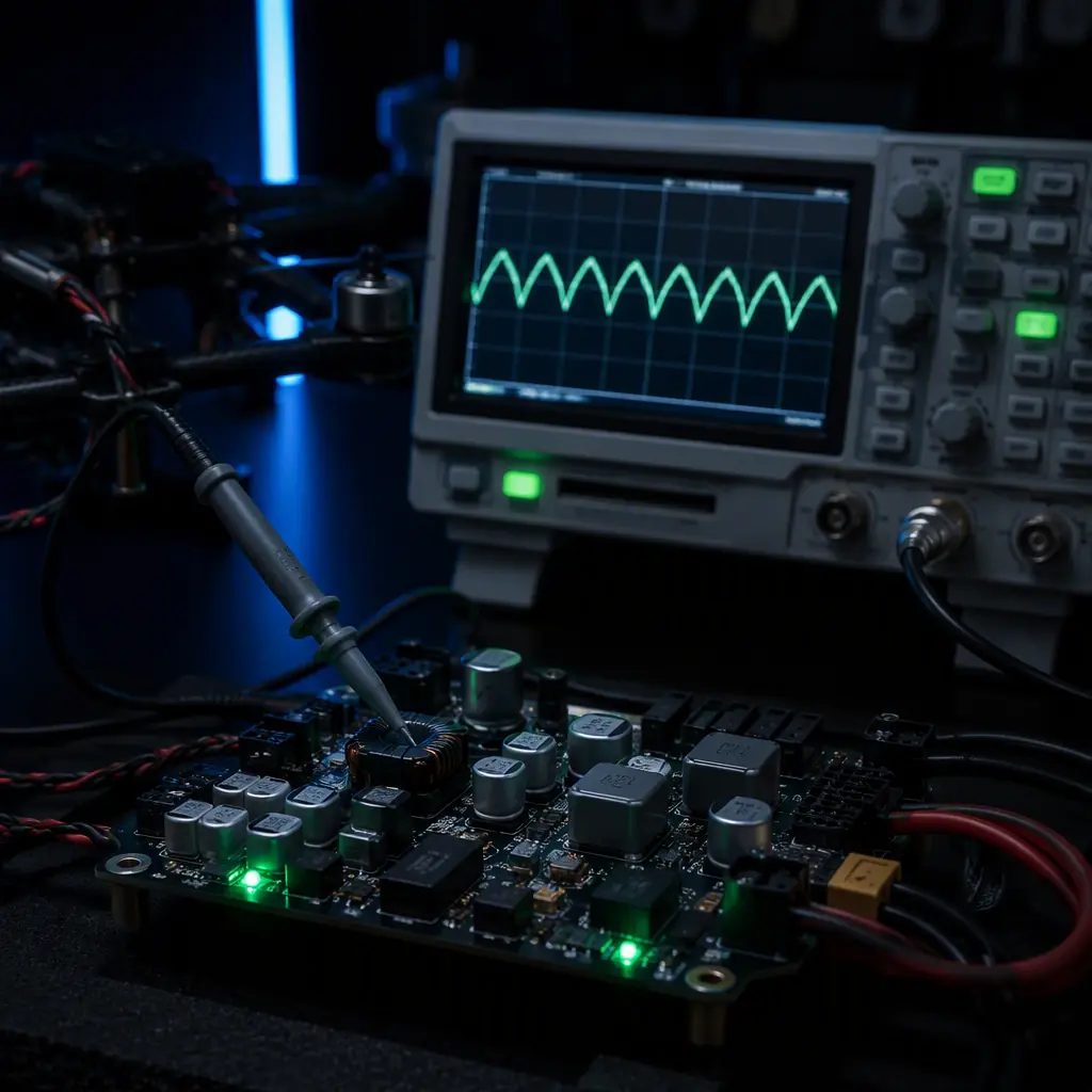
8. Load-step test data. A measured load-step response for each rail (the rail's voltage deviation when the payload's peak load is applied), which is the single best predictor of brownout behavior in the field. Verification: the oscilloscope captures from the test program.
The payload power architecture closes the loop with the rest of the aircraft documentation: the battery and power management guide for the pack, the onboard computing guide for the biggest payload load, and the EMC/EMI guide for the compliance envelope the whole power system must live inside.
Explore custom engineering Back to Blog
Both the payload power hardware and the regulated power stages are built in-house at EMS Drone, which means the interfaces between them are specified by the same team. Review the hardware we manufacture if you are scoping a build, or read how we handle the adjacent subsystem.
Continue Reading
UAV Battery and Power Management
LiPo vs Li-Ion chemistry, pack sizing and BMS behavior, the source-side of the power budget this guide spends on the payload side.
UAV Connectors, Wiring & Power Distribution
PDB design, wire gauge and connector families. The physical layer that carries the payload rails without unacceptable drop.
UAV Payload Integration: Sensors, Gimbals and Release Mechanisms
The electrical, mechanical and data sides of payload integration, the framework this power guide sits inside.
UAV Edge AI & Onboard Computing
Companion computers and their power-hungry load profiles, the largest single consumer in most payload budgets.
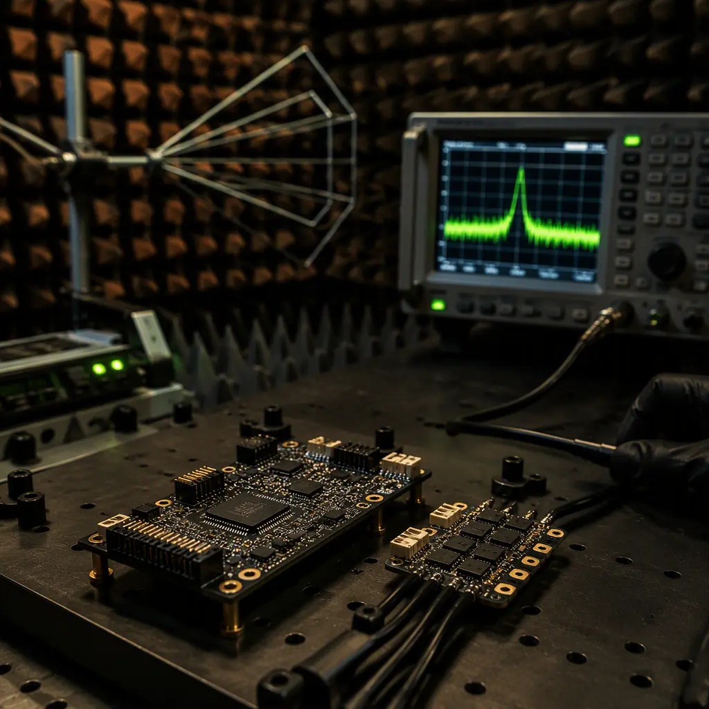
UAV Avionics EMC/EMI Design & Compliance
The radiated and conducted noise envelope that switching converters must live inside, the compliance side of payload filtering.