
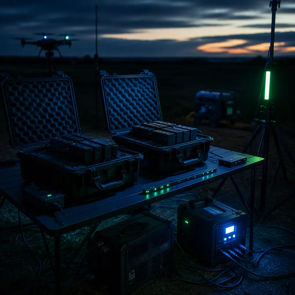
The airframe and the battery chemistry decide how much energy a sortie needs; the ground equipment decides whether that energy can be delivered fast enough to keep the fleet flying. The battery and power management guide covers the cell-level side of that equation, the chemistry choice that sets the energy available per pack. This guide covers everything downstream of the pack: the source, the conversion, the safety and the logistics that turn a charging problem into a field procedure.
Sizing the field power budget: from watt-hours per sortie to kilowatt-hours per day
The field power requirement is a multiplication, not a guess: energy per sortie × sorties per day × a margin for charging losses and parallel charging overhead. The energy per sortie comes from the mission profile, a 5 kg multirotor inspection platform drawing 300–600 Wh per sortie, a logistics aircraft at higher payload burning more, a fixed-wing survey platform at cruise burning less per kilometer. The payload power budgeting guide is the method for computing the per-sortie figure from the per-phase power draw.
| Fleet scenario | Energy per sortie | Sorties per day | Field energy need |
|---|---|---|---|
| Inspection multirotor, 5 kg class | 400 Wh | 8 | 3.2 kWh |
| Mapping fixed wing, 5 kg class | 250 Wh | 6 | 1.5 kWh |
| Delivery multirotor, 10 kg class | 800 Wh | 10 | 8.0 kWh |
| Agriculture spraying, 25 kg class | 2,500 Wh | 6 | 15 kWh |
Charging losses add 10–20% on top of the pack energy, charger efficiency, balancing overhead and the energy spent conditioning packs. The honest planning number is 1.2× the pack energy. A 3.2 kWh sortie demand becomes a 3.8 kWh generator load, which is the difference between a 2 kW and a 3 kW machine once the charging peaks are included. The second constraint is time: ten sorties at 1C charge with four packs on parallel boards means a charging window between flights. The ground equipment must deliver the energy within the turnaround time, not just by the end of the day.
 Concept illustration
Inverter generators: the workhorse baseline
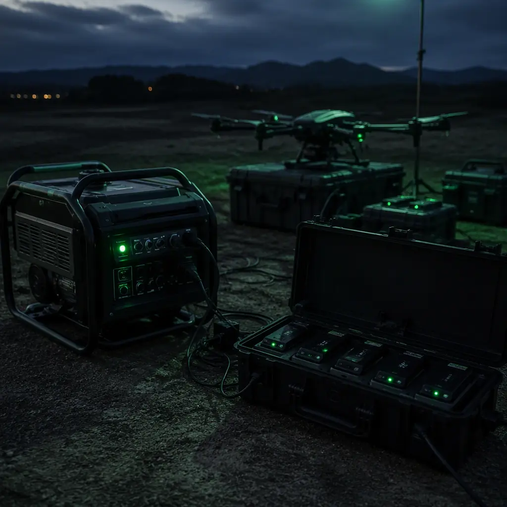
For any operation above about 2 kWh per day, an inverter generator is the pragmatic baseline. The class matters more than the brand: inverter generators produce clean, stable AC (total harmonic distortion typically under 5%) that switch-mode chargers tolerate well, run at variable engine speed to match the load, and are quiet enough for most field sites. A 2.2–3.5 kW inverter generator covers a parallel charging setup drawing 1.5–2.5 kW with margin, and burns roughly 0.4–1.2 liters of fuel per hour depending on load. A full field day of 6–8 charging hours sits in the 3–8 liter range.
The specifications that matter for UAV field work:
- Rated continuous output vs peak. Chargers draw sustained current, not brief spikes, size the continuous rating to the charging load, not the surge figure. Parallel charging four 6S packs at 1C can pull 1.5 kW continuously.
- Altitude derating. Above 1,500 m, generator output falls roughly 3.5% per 300 m. A "3.5 kW" machine at 3,000 m delivers closer to 2.6 kW, a real constraint for mountain survey operations.
- Fuel logistics. A day of field charging is 3–8 liters of fuel plus transport and storage rules; operations in sensitive sites (national parks, border areas) may prohibit fuel entirely, which pushes the design toward solar or battery banks.
- Noise and site approval. Quiet inverter units run 52–62 dBA at 7 m, acceptable in most agricultural and industrial settings, a permitting problem in residential or protected areas.
Generator maintenance is a line item fleets forget: oil changes, spark plugs and carbon brush wear on the alternator. The spares and lifecycle planning guide frames the same logic for ground equipment that it applies to aircraft components. The generator is part of the fleet's reliability chain, not an afterthought.
Solar and portable power stations: when fuel is not an option
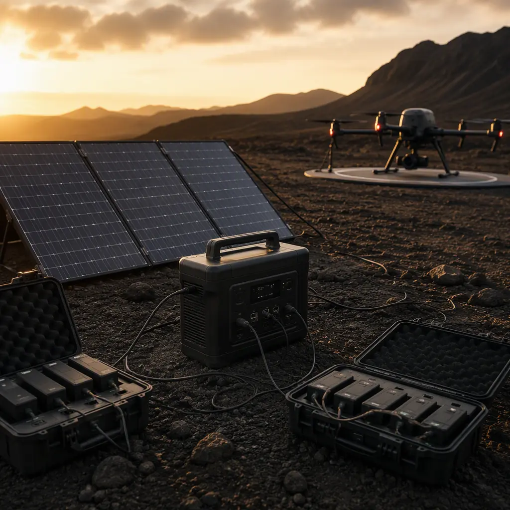
Solar becomes the primary source when fuel is prohibited, when the operation is stationary for days (wildfire monitoring, border patrol, environmental surveys), or when the site has no vehicle access. The honest sizing math: a field site gets 4–6 peak sun hours per day in most operating regions; a 300 W folding panel array produces roughly 1.2–1.8 kWh per day. That is the entire energy budget for a light inspection fleet, and nowhere near enough for an 8 kWh delivery operation. Solar in UAV field work is a range extender and a battery conditioner, not a primary source, unless the operation is deliberately sized around it. The solar and hybrid power guide covers the airborne side of the same technology; the ground side follows identical physics.
Portable power stations (500 Wh to 3.6 kWh) fill the middle role: silent, zero-emission, and fast to deploy, at the price of capacity and recharge time. Three procurement notes:
- DC output beats AC. Charging from a power station's 12 V or 24 V DC output avoids the 10–15% inverter loss of going DC→AC→charger→pack. Many stations deliver more wattage on DC than on AC.
- Capacity is not usable energy. A 1,000 Wh station at 80% depth-of-discharge delivers 800 Wh. And a 6S 16,000 mAh pack needs ~360 Wh at the wall, so a "big" station charges only two packs before it needs recharging itself.
- Recharge from vehicle or solar. A station paired with vehicle DC charging during transit, or with panels at a stationary site, becomes a buffer that smooths the generator runtime instead of replacing it.
 Concept illustration
Vehicle-based DC charging: the quiet option that has limits
Every field truck is a potential charging source, but the numbers discipline the idea. A standard 12 V accessory socket is fused at 10–15 A, 120–180 W of usable power, which charges a 6S pack in four to six hours. That is a trickle, not a charging solution. The workable versions of vehicle charging:
- Direct-to-battery DC-DC charging. A 12 V to 24 V (or matched pack voltage) DC-DC converter wired to the vehicle battery, fused and isolated, delivers 300–600 W. This charges a pack in roughly an hour and is the standard setup for survey trucks that move between sites.
- Alternator capacity check. A stock alternator produces 90–150 A; heavy auxiliary loads (winches, lighting, charging) on top of the vehicle's own draw can exceed it at idle. The DC-DC charger must be sized against the alternator's surplus, and engine-idling restrictions at some sites make this a permitting question as much as an electrical one.
- Charging while driving. The practical pattern is charging during transit between sites, not at idle: the vehicle alternator is already loaded, the engine is already running, and the energy is effectively free. The logistics and delivery components guide shows how delivery fleets structure the same transit-charging pattern around sortie schedules.
The wiring standard matters: vehicle charging introduces ground loops and voltage transients that can damage charger inputs. The connectors and power distribution guide covers the harness, fuse and isolation practice for auxiliary power in the field environment.
Battery swap and hot-swap logistics: the fleet multiplier
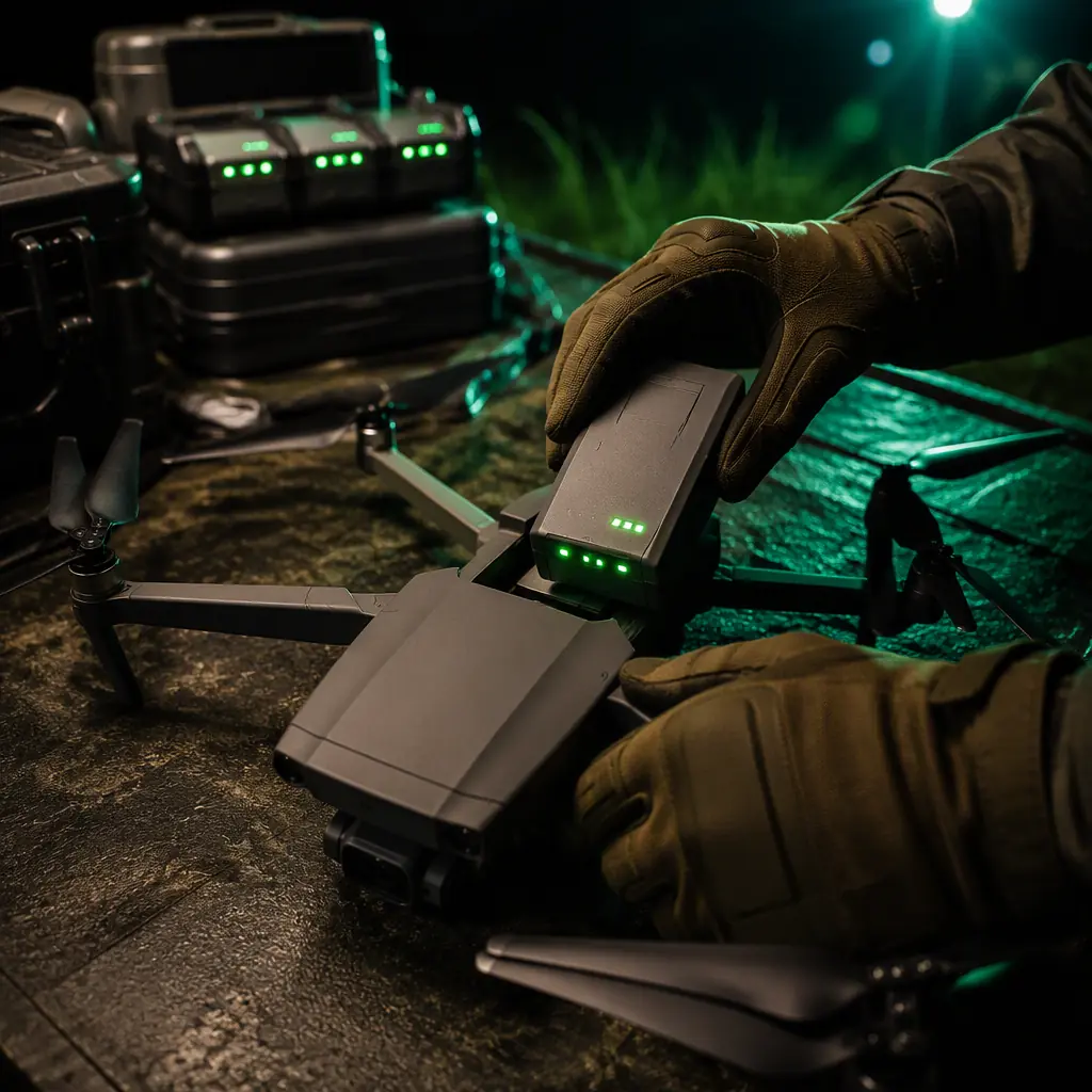
The fastest way to increase sortie throughput is not a bigger charger, it is more packs. Battery swap decouples the aircraft from the charging cycle: the aircraft lands, the operator swaps a depleted pack for a charged one in under a minute, and the aircraft is airborne while the charger catches up. The logistics that make swap work:
- Pack count planning. With a 1C charge rate, each pack charges in roughly an hour; a fleet flying 10-minute swaps needs a minimum of (flight time + charge time) / flight time packs. For a 30-minute flight and 60-minute charge, that is three packs per aircraft, with a fourth as buffer. Fewer packs than the math demands is the most common throughput mistake in field operations.
- Pack identity and tracking. Swappable packs must be individually identified (label, QR or BMS ID) with cycle counts and capacity history logged per pack. Packs age unevenly; a swap system without per-pack records hides the weak cell until it fails in the air. The fleet management guide covers the telemetry and maintenance-logging layer that tracks pack health across the fleet.
- Hot-swap mechanical design. The swap interface, rails, locking mechanism, connector, is a wear item rated for hundreds of cycles. The connector and mount should be specified for the cycle count, not the first flight.
- Swapped packs still need a charging plan. Swap multiplies the number of packs, which multiplies the charging load and the storage requirement. A 6-aircraft fleet with 4 packs each is 24 packs in rotation. The field power budget must cover charging them all between sorties, and the storage must keep the resting packs at storage voltage.
 Concept illustration
Charging safety and thermal management: where field operations go wrong
Field charging concentrates the two most dangerous elements of UAV operations, high-capacity lithium packs and unattended charging in improvised environments. The failure modes and the mitigations are well documented:
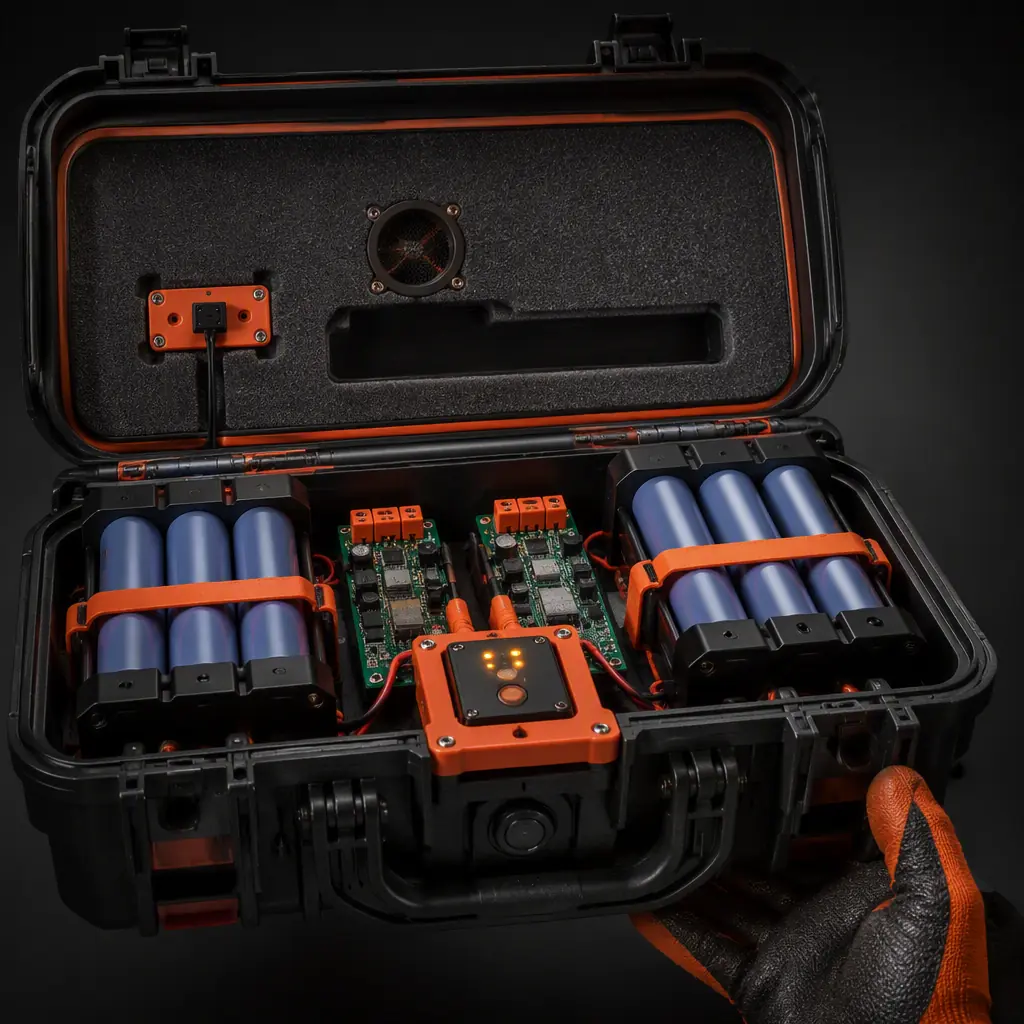
- Thermal runaway containment. LiPo and Li-Ion packs charge into fire risk if a cell is damaged, overcharged or internally shorted. Charging must happen in fire-rated containment, a charging case or bag rated for the pack size, on a non-flammable surface, away from the aircraft and the vehicle. This is not optional in a field environment where the nearest fire service is an hour away.
- Cold-weather charging. Charging lithium below roughly 0 °C damages cells through lithium plating; the pack must be warmed to operating temperature before charging. Field kits for winter operations include insulated boxes and heating pads, the same thermal discipline covered in the thermal management guide, applied on the ground side.
- Parallel charging boards. Parallel charging multiplies throughput and multiplies risk. A damaged pack in a parallel bank can draw current from its siblings. The rules: only identical packs in parallel, a balance-lead check before connecting, and a current limit per board.
- Storage voltage discipline. Packs that sit between sorties, or overnight, should rest at 3.7–3.85 V per cell, not at full charge. Full-charge storage is the fastest way to degrade cycle life, and the battery management guide quantifies the capacity-loss curve.
- Transport rules. Moving packs between sites by road or air is regulated: many air-freight rules require lithium packs below 30% state of charge, which changes the field charging plan at the end of a deployment.
 Concept illustration
Fleet integration: power tracking and battery life data
The ground power chain generates data that most fleets throw away: watt-hours delivered per pack, charge cycles, charge temperatures, pack capacity trends. That data is the fleet's battery health record, and it belongs in the same maintenance system as flight hours and component logs. A pack that loses 20% of its capacity in 150 cycles is a different procurement problem from one that holds 90% at 300 cycles, the spares and lifecycle guide shows how cycle-life data drives MTBF planning and spare-kit composition. The field charging log is also the evidence trail for warranty claims, the warranty and RMA guide lists the charging records that suppliers (including EMS Drone) ask for when a pack failure is investigated.
The integration rule: charging infrastructure should log per-pack energy and cycle data automatically where possible, and the log should be reviewed per deployment, not per year. A charging station is the fleet's second-most-instrumented asset after the aircraft itself.
Procurement checklist: the RFQ clauses for ground power equipment
When the field power requirement is computed, the RFQ for ground equipment should carry six clauses:
1. The mission profile and the energy math. Sorties per day, watt-hours per sortie, charging window between flights, and the 1.2× loss margin. Verification: the supplier's equipment sizing against this stated budget, the same discipline as the propulsion testing and validation approach applied to ground power.
2. Continuous power at the operating altitude. The generator or power station rated continuous output, derated for the maximum site altitude. Verification: the derating table, not the marketing wattage.
3. Clean power and charger compatibility. Output waveform, THD, and demonstrated compatibility with the fleet's chargers. Verification: a charging test with the actual charger model before the equipment ships.
4. Safety and containment kit. Fire-rated charging cases, thermal monitoring, cold-weather provisions and the storage-voltage procedure. Verification: the kit list and the field procedure document.
5. Battery tracking integration. Per-pack logging of cycles, energy and capacity, compatible with the fleet management system. Verification: the export format and a sample log.
6. Logistics fit. Fuel rules, transport restrictions, weight and volume per vehicle, and the setup/teardown time per site. Verification: the field deployment plan.
The decision, in one line: compute the field energy budget from the mission plan, choose the source that fits the site constraints (generator for throughput, solar and storage where fuel is prohibited, vehicle DC for transit charging), multiply the pack count to decouple aircraft from chargers, and contain the charging in rated safety equipment. EMS Drone supplies the battery systems, the matched charging architecture and the integration support for field operations. Send the sortie profile and the site constraints, and we will respond with the pack count, the charging equipment list and the field procedure for a fleet that stays airborne.
Explore custom engineering Back to Blog
EMS Drone manufactures battery and power systems under one roof, from component sourcing through production test. If you are specifying for a build, see the full capability set and the tolerances we hold.
Continue Reading
UAV Battery and Power Management
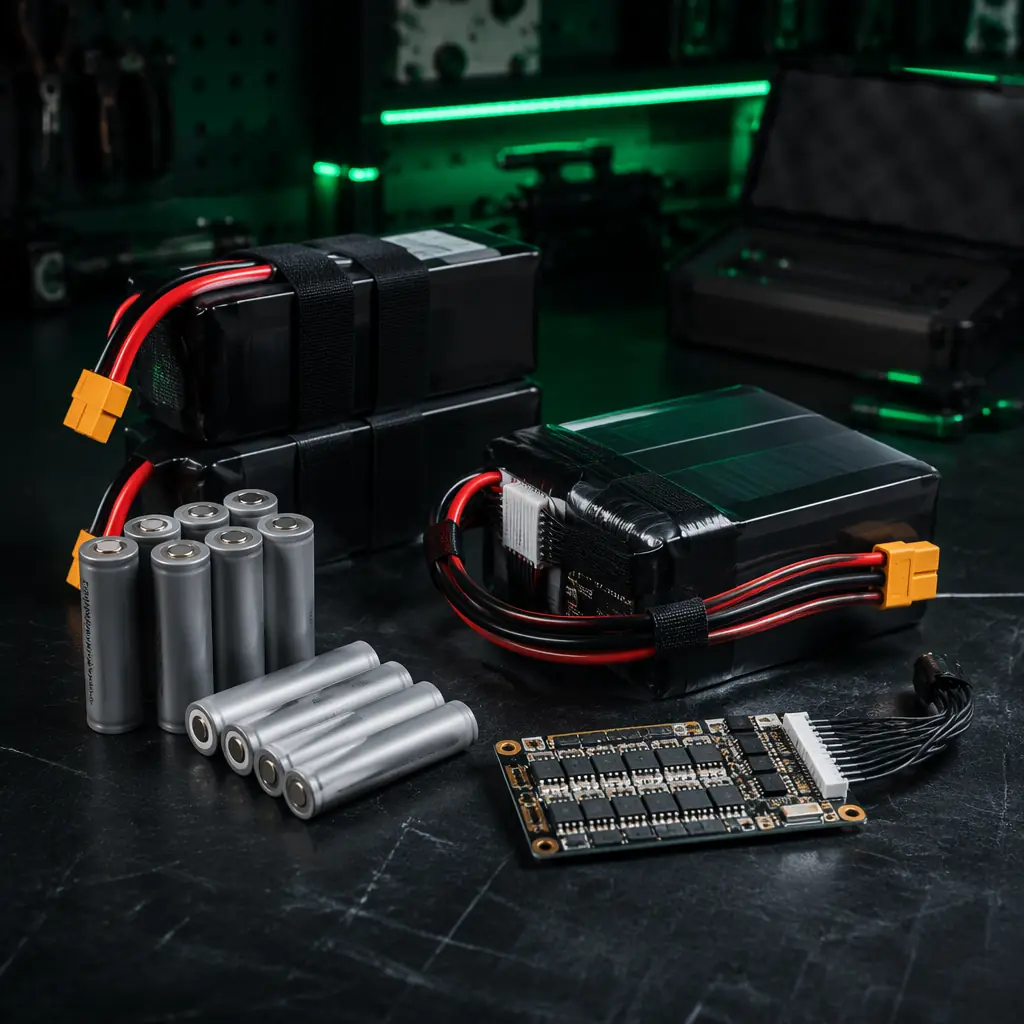
The cell-level side of the field power equation, LiPo vs Li-Ion, pack sizing and the charging rules that protect cycle life.
UAV Components for Logistics and Delivery
How delivery fleets structure transit charging and swap logistics around high-sortie-rate schedules.
UAV Fleet Management Components
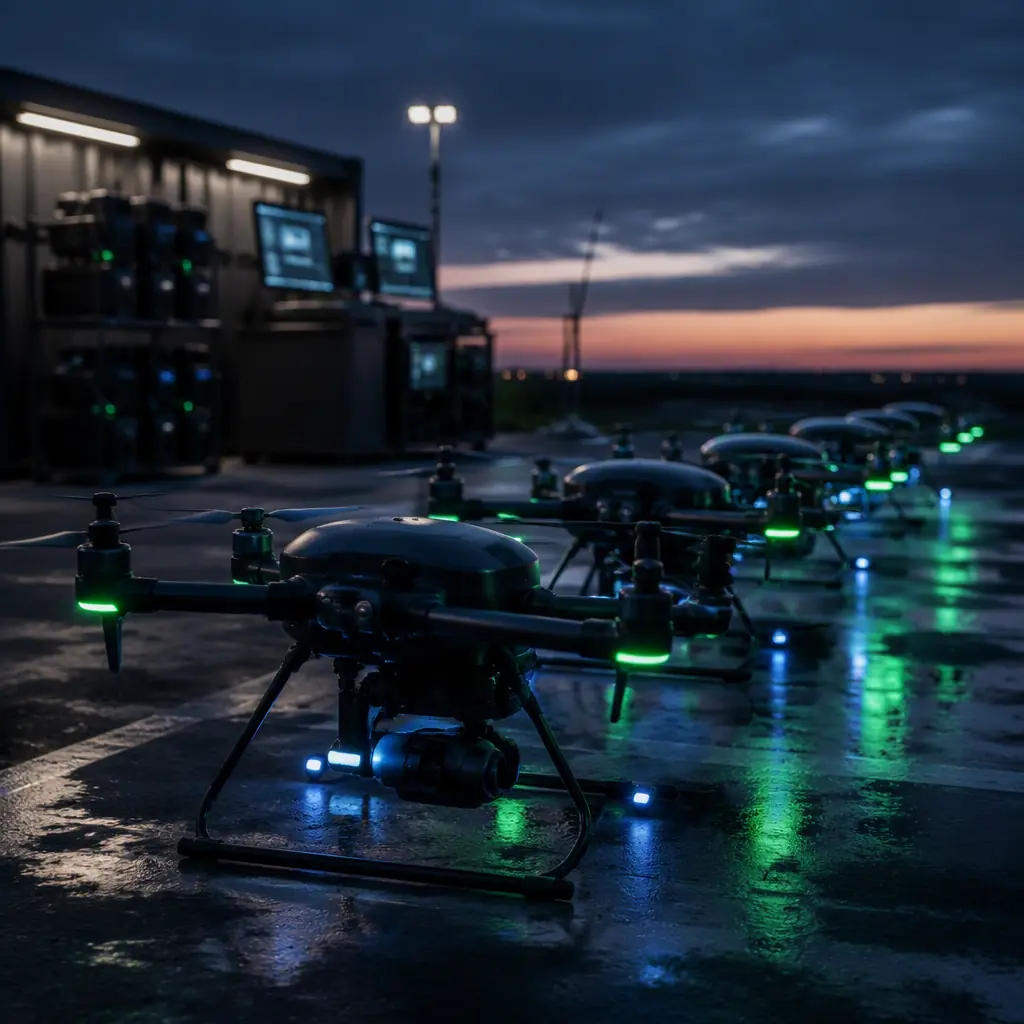
The telemetry and maintenance-logging layer that tracks pack health and charging data across the fleet.

UAV Spares and Lifecycle Planning
Cycle-life data, spare-kit composition and TCO, the planning frame for battery-heavy field operations.
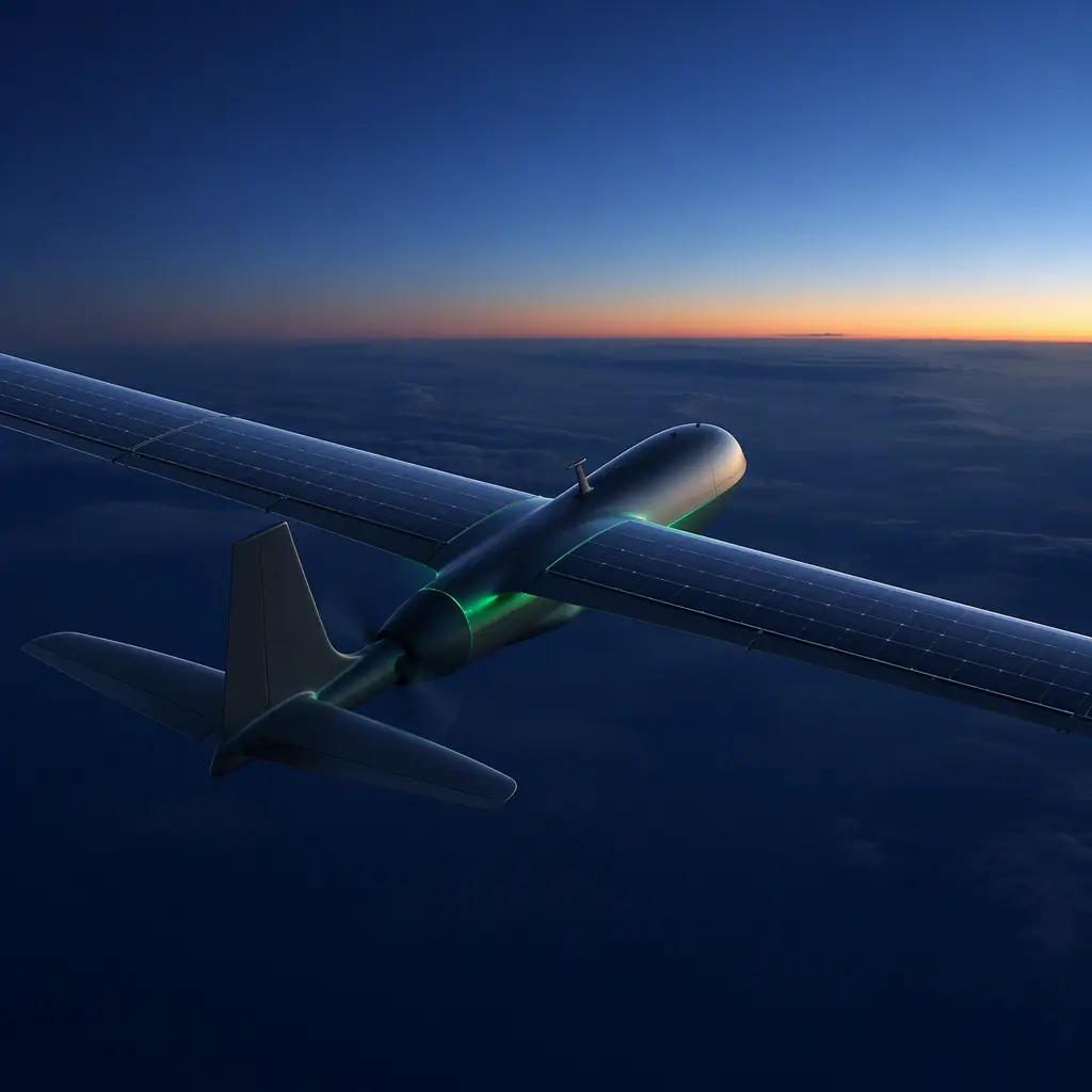
UAV Solar and Hybrid Power
The airborne side of solar, endurance beyond the battery, and how it changes the field charging requirement.