Industrial UAVs operating beyond visual line of sight (BVLOS), over populated areas, or carrying payloads worth tens of thousands of dollars share one non-negotiable requirement: navigation must survive a single-point sensor failure without interruption. A flight controller running at 8 kHz IMU and 1 kHz control loop rates processes 8,000 attitude samples per second. If even one of those samples is corrupted by an IMU that drifted into saturation mid-flight, the resulting control output can put the aircraft into an unrecoverable attitude within 200 milliseconds — faster than a human operator can react, even with a direct video feed.
Redundant navigation is not about buying two of everything and hoping the second one works when the first one fails. It is an architectural decision that spans sensor selection, voting logic, fault detection thresholds, and the extended Kalman filter (EKF) implementation that fuses multiple sensor streams into a single state estimate. This article covers each layer of that architecture, from the IMU silicon to the failover response of the flight controller, with specific component-level criteria that procurement teams can use to evaluate flight controller suppliers.
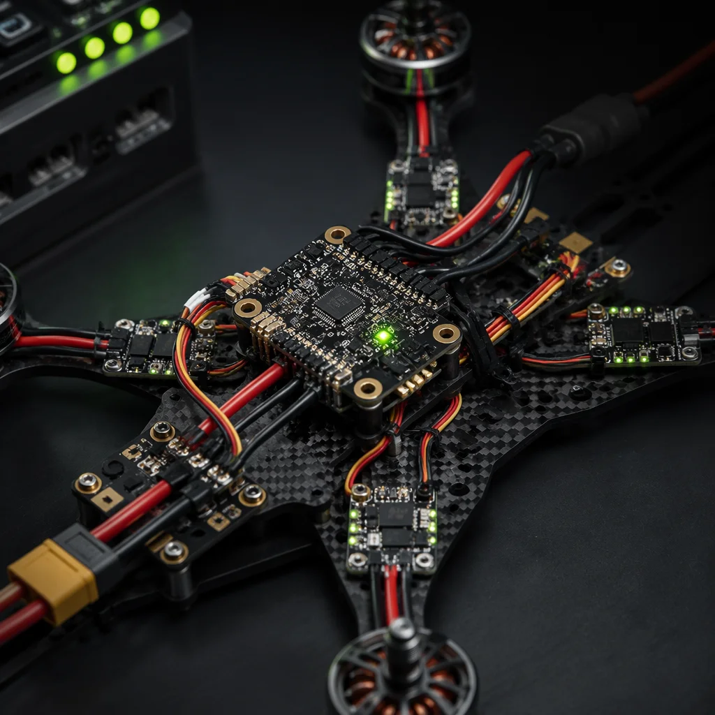
The baseline: a properly architected redundant navigation system degrades gracefully. A dual-IMU configuration with a median-voting arbitrator detects a failed gyro within 3–5 IMU sample periods (375–625 microseconds at 8 kHz) and switches to the healthy IMU before the EKF innovation gate widens enough to degrade the state estimate. A triple-IMU configuration — increasingly common on survey-grade and defense UAVs — can tolerate a complete IMU failure and still maintain a 2-of-3 consensus, buying time for a controlled return-to-home rather than an immediate forced landing. Understanding how these architectures map to real flight controller hardware is the foundation of matching flight controllers and ESCs for safety-critical platforms.
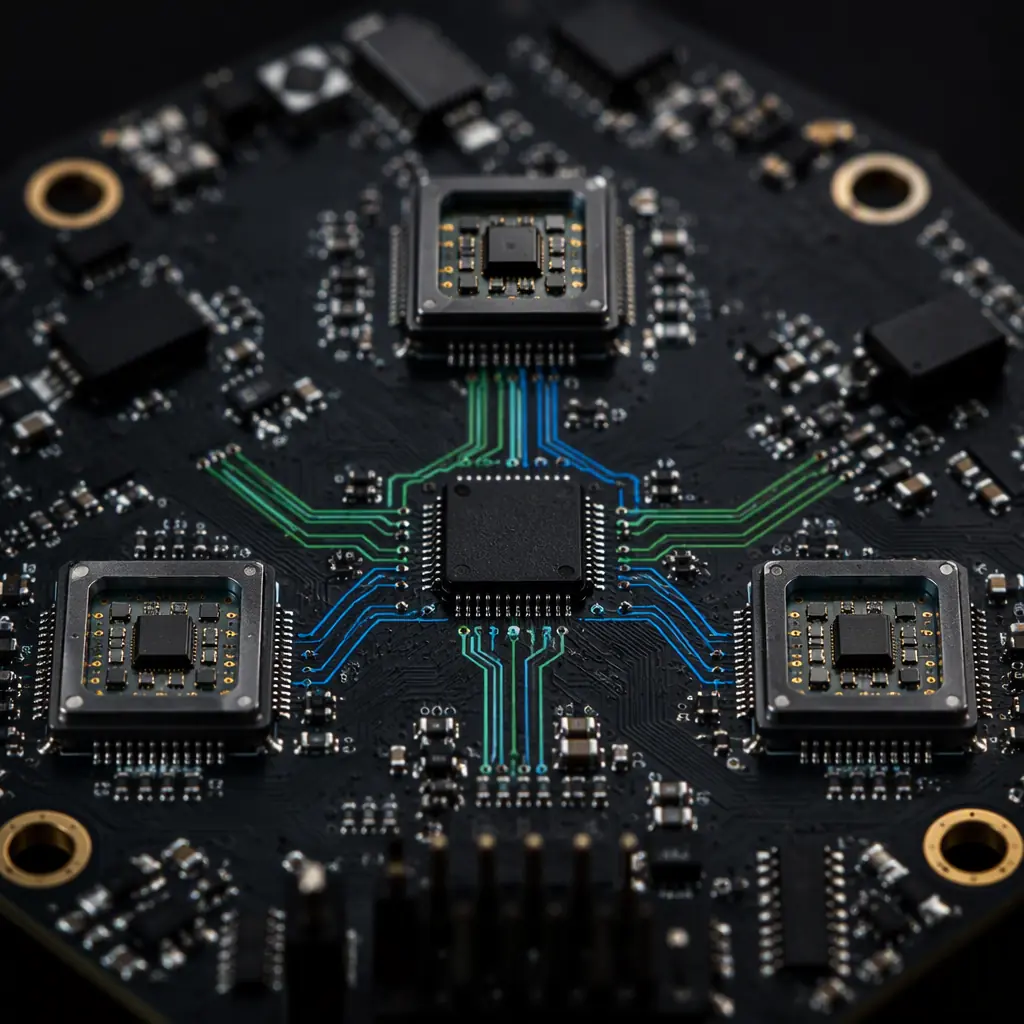 Redundant navigation architecture
IMU redundancy architectures: dual, triple and heterogeneous configurations
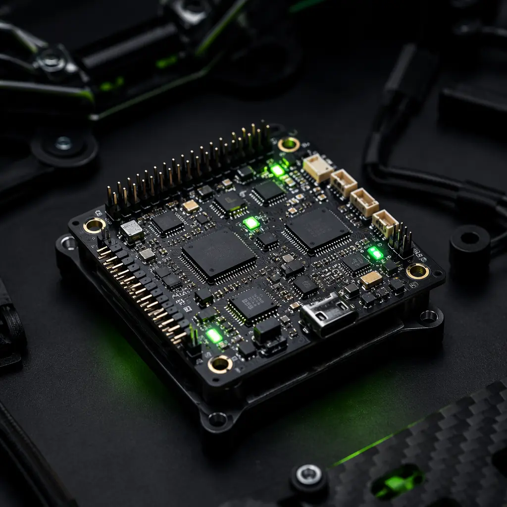
The simplest redundancy — dual IMU with a hardware comparator — catches gross failures (IMU output stuck at zero, saturated at full scale, or producing NaN values) but cannot resolve which IMU is correct when the two disagree. The standard industrial approach is a triple-IMU configuration with a 2-of-3 median voter: each IMU runs independently on its own SPI bus, the flight controller reads all three at 8 kHz, and the navigation EKF uses the median of the three angular rate measurements for each axis. When one IMU diverges from the other two by more than a configurable threshold — typically 3–5 times the expected noise density of the sensor — it is flagged as unhealthy, and the EKF switches to using only the two healthy IMUs until the third recovers or is permanently excluded.
The component-level implications are significant. A triple-IMU architecture requires a flight controller with at least three independent SPI buses — not three devices sharing one bus, which would create a single point of failure in the bus controller. It also requires the IMU chips to be physically separated on the PCB by at least 20 mm to avoid common-mode vibration coupling; two IMUs mounted adjacent to each other on the same board will experience nearly identical vibration spectra and may fail in the same way under resonance. For procurement, ask whether the flight controller supplier validates IMU voting logic through hardware-in-the-loop testing with injected IMU faults — not just a software simulation. A supplier that cannot describe their IMU fault injection test setup has not validated the redundancy they claim.
Heterogeneous IMU configurations add a further layer: using two different IMU models — for example, a Bosch BMI088 for primary attitude and an InvenSense ICM-42688-P for the redundant channel — protects against common-mode failures that affect a specific sensor die revision or firmware bug. The trade-off is that the EKF must be tuned to handle two different noise models simultaneously, which requires more careful covariance matrix configuration. For platforms where a single IMU vendor's errata could ground an entire fleet, heterogeneous IMU selection is worth the integration complexity. This is the same procurement philosophy behind component obsolescence management — do not let one supplier's silicon become your single point of failure.
Dual GNSS with RTK: beyond "two antennas"
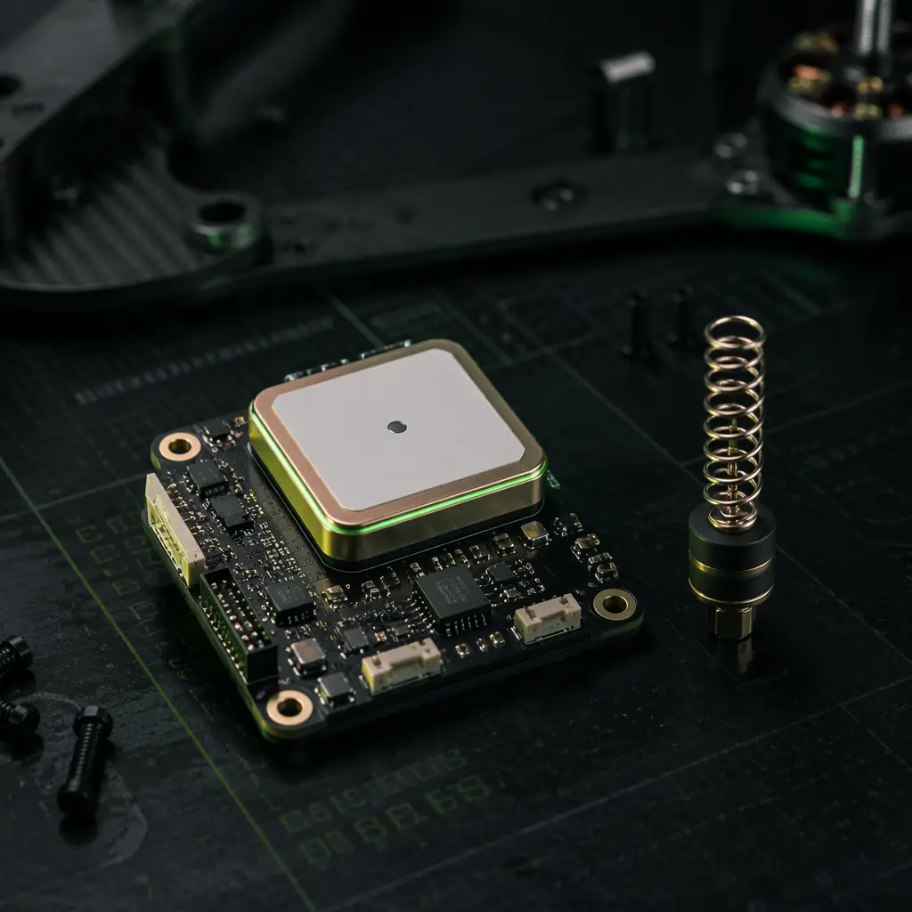
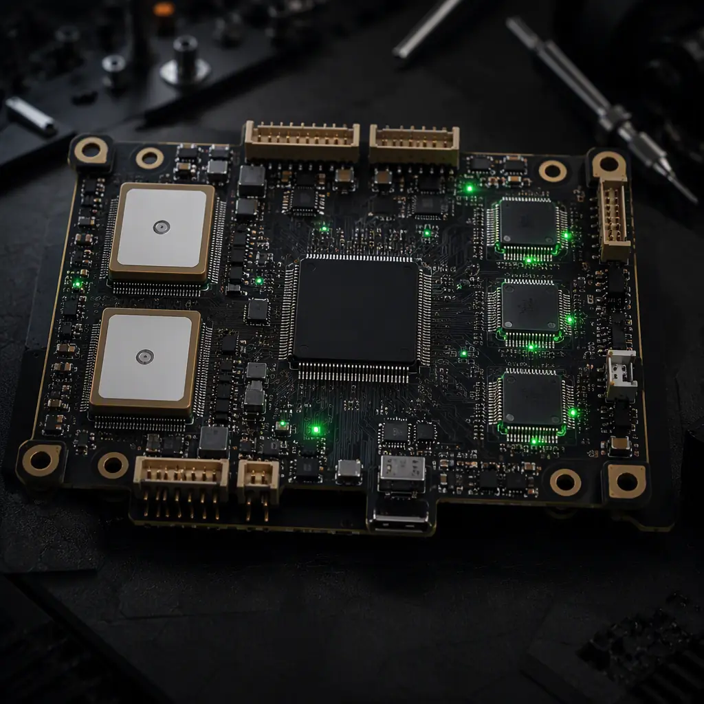
Dual GNSS on a UAV is often described as "two GPS modules for redundancy," but that description misses the architecture. A properly implemented dual-GNSS system provides three capabilities that a single-GNSS system cannot: position redundancy with cross-check, moving-baseline heading without a magnetometer, and RTK integer-ambiguity validation through inter-receiver comparison.
The hardware requirements are non-trivial. Each GNSS receiver needs its own antenna with at least 30 cm of physical separation to decorrelate multipath reflections. Both receivers must share a common clock reference or be synchronized through a PPS (pulse-per-second) signal with sub-microsecond jitter. For RTK operation, the primary receiver receives corrections from a base station or NTRIP caster; the secondary receiver can operate in two modes: independent RTK (both receivers solve their own integer ambiguities, results are compared at the navigation filter) or moving-baseline mode (the secondary receiver computes a relative vector to the primary, providing heading with 0.1–0.3 degree accuracy at 1-meter antenna separation).
For procurement evaluation, the key questions are: does the flight controller support dual u-blox F9P or ZED-F9R receivers with independent UART connections? Can the EKF compare the two GNSS position solutions and reject one that diverges by more than 3× the reported standard deviation? And critically, does the system provide a GNSS health flag that the autopilot can act on — switching from GNSS-aided navigation to pure inertial navigation with a configurable timeout — rather than simply logging the discrepancy for post-flight analysis? A flight controller that detects GNSS divergence but continues to use the corrupted position in the EKF is worse than one with a single GNSS that simply reports degraded accuracy. For platforms that depend on precision positioning, the GNSS RTK module selection guide covers the receiver-level criteria in detail.
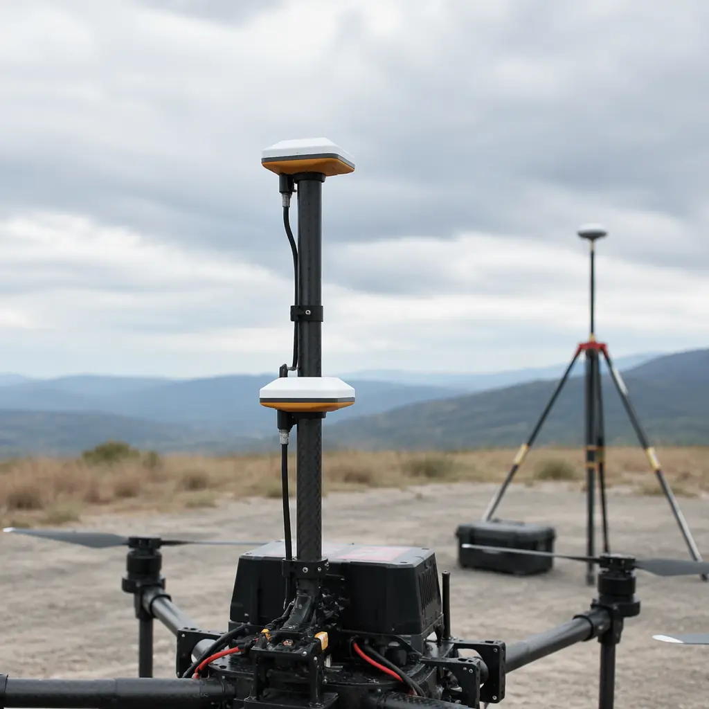 Dual GNSS configuration
Extended Kalman filter architecture: the fusion engine
The EKF is where redundancy becomes navigation. A well-tuned 24-state EKF for a multirotor UAV tracks: 3 position states, 3 velocity states, 4 attitude quaternion states, 3 gyro bias states, 3 accelerometer bias states, 3 magnetometer bias states, 2 wind velocity states (North/East), and 3 GNSS receiver clock states. Each redundant sensor adds observations — not states — to the filter. A dual-IMU system feeds two sets of angular rate and acceleration observations into the same 24-state filter; the EKF innovation (the difference between predicted and observed measurements) becomes the fault detection signal.
The EKF innovation gate is the critical parameter. When an IMU gyro begins to drift — producing angular rate measurements that diverge from what the other IMUs and the GNSS velocity solution predict — the innovation for that sensor's observations increases. If the innovation exceeds 3–5 standard deviations of the expected measurement noise (typically 0.05–0.15 dps/√Hz for industrial-grade MEMS gyros), the EKF either down-weights that sensor's contribution or rejects the observation entirely for that update cycle. This is fundamentally different from a simple median voter: the EKF can detect a slowly degrading IMU — one whose bias is drifting at 0.1 degrees per minute — hundreds of milliseconds before the raw measurements diverge enough to trigger a simple threshold comparator.
The practical procurement question: does the flight controller's EKF implementation expose sensor health flags over MAVLink or DroneCAN that a companion computer or ground control station can consume? If the only indication of IMU degradation is a subtle increase in the EKF innovation variance buried in a debug log, the redundancy exists in theory but not in operational practice. The best implementations, such as those in ArduPilot's EKF3 and PX4's EKF2, publish real-time innovation test ratios for each sensor stream at the navigation output rate — typically 50–100 Hz on a 1 kHz control loop — allowing ground station software to display a live sensor health dashboard. For teams evaluating the ArduPilot versus PX4 decision, the EKF implementation quality — including redundant sensor handling — should carry significant weight.
Barometer and magnetometer fusion: the often-overlooked redundancy layer
Triple IMU and dual GNSS get the attention, but barometer and magnetometer redundancy is equally important for specific failure modes. A single barometer exposed to direct propeller downwash can produce altitude estimates with 2–5 meter errors under gusting wind — enough to cause a ground collision during an autonomous landing if the GNSS altitude solution is also degraded. Three barometers (BMP390 or MS5611 class sensors, each with its own I²C bus and static pressure port) with a median voter can maintain altitude accuracy within 0.5 meters even when one sensor is contaminated by dynamic pressure.
Magnetometer redundancy is architecturally harder because magnetometers are sensitive to both hard-iron and soft-iron distortions from the UAV's own power system. A dual-magnetometer configuration with 10 cm of physical separation provides some protection against local magnetic interference — for example, one magnetometer mounted on a GPS mast 15 cm above the airframe and a second mounted on the flight controller PCB can detect magnetic anomalies generated by high-current ESCs drawing 40–80 A under load. The EKF compares the two magnetometer heading estimates; if they diverge by more than 10–15 degrees after accounting for the known hard-iron offset between the two mounting locations, the filter rejects both magnetometer observations and relies on GNSS heading from moving-baseline or dual-antenna computation.
For VTOL platforms that transition between hover and forward flight, magnetometer fusion is particularly challenging because the hard-iron and soft-iron distortion matrices change with motor current draw. The propulsion system draws 3–5× more current in hover than in forward flight, which means the magnetic environment the magnetometer sees is fundamentally different in each flight phase. A flight controller that uses a single magnetometer calibration valid for only one flight regime will produce heading errors of 15–30 degrees during transition. The VTOL transition components guide covers the broader propulsion and control implications, but from a sensor fusion perspective, the requirement is clear: the flight controller must support phase-dependent magnetometer calibration tables — or it must fuse dual GNSS heading as the primary heading source during transition, with magnetometer as a fallback only.
Failover logic and degraded-mode operation
Redundancy is only as good as the failover logic that activates it. The worst failure mode in redundant navigation is not a sensor failure — it is a failover that oscillates between primary and backup sensors because the fault detection threshold is set too tight, or a failover that does not activate at all because the threshold is set too loose. Both failure modes have caused real-world UAV losses.
A robust failover system implements hysteresis: once a sensor is flagged as unhealthy, it requires a sustained period of healthy readings — typically 5–10 seconds of innovation values within the acceptance gate — before it is re-admitted to the EKF. Without hysteresis, a sensor operating near the noise boundary can toggle between healthy and unhealthy states at 10–20 Hz, causing the EKF to repeatedly re-initialize its covariance matrix for that observation channel. Each re-initialization resets the filter's confidence in that sensor, effectively discarding the benefit of redundancy.
The degraded-mode hierarchy for a fully redundant system should be: (1) triple IMU + dual GNSS + EKF = full performance; (2) dual IMU + single GNSS = position accuracy degrades from centimeter to meter-level, attitude remains accurate; (3) single IMU + no GNSS = pure inertial navigation, position drift of 1–3 meters per second of GNSS outage, attitude drift of 0.1–0.5 degrees per minute depending on gyro bias stability; (4) single IMU with gyro saturation = emergency landing mode, control loops switch to accelerometer-only attitude estimation, altitude maintained by barometer. Each degradation step should trigger a distinct MAVLink status message so the ground station — and the operator — understand exactly which sensors are still contributing to the navigation solution.
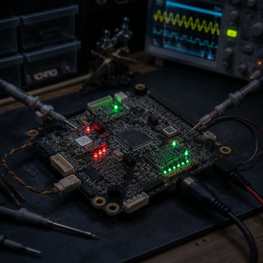 Failover test configuration
Procurement checklist: evaluating flight controllers for redundant navigation
When evaluating a flight controller supplier's redundant navigation capability, move past the marketing claim of "triple redundant IMU" and verify the implementation. The following checklist items map directly to procurement-grade qualification criteria:
1. Independent sensor buses. Confirm that each IMU, each GNSS receiver and each barometer has its own dedicated SPI, UART or I²C bus — not shared buses with multiple devices. Request a block diagram of the sensor bus architecture. A flight controller with three IMUs sharing a single SPI bus through a multiplexer has a single-point failure at the bus controller.
2. Physical sensor separation. Verify IMU-to-IMU spacing on the PCB layout (minimum 20 mm) and GNSS antenna separation (minimum 30 cm for moving-baseline heading). Physical separation reduces common-mode vibration coupling and multipath correlation.
3. Fault injection test results. Request a test report showing EKF behavior during simulated IMU gyro failure (bias drift at 0.5°/s, saturation at full scale, and complete signal loss), GNSS spoofing or loss, and barometer blockage. The report should show innovation test ratios before, during and after the injected fault.
4. MAVLink health telemetry. Verify that sensor health flags — per-IMU innovation variance, per-GNSS position standard deviation, barometer status — are published at the navigation output rate (50–100 Hz) on standard MAVLink messages (HIGH_LATENCY2, EKF_STATUS_REPORT, or equivalent). If these flags are only accessible through a vendor-specific debug protocol, they are not operationally useful.
5. Degraded-mode documentation. The supplier should provide a documented degraded-mode hierarchy: what navigation performance is available under single-IMU, single-GNSS, and pure-inertial conditions. If this documentation does not exist, the redundant architecture has never been characterized in the failure modes that matter.
6. Environmental test data. For platforms operating in extreme environments, request IMU performance data across the full operating temperature range. A MEMS gyro with 0.05 dps/√Hz noise density at 25°C may degrade to 0.15 dps/√Hz at -20°C — which changes the effective redundancy threshold and may cause the EKF to reject a healthy IMU in cold conditions. This thermal behavior should be characterized, not discovered mid-flight. The testing methodology parallels the broader validation approach described in UAV propulsion testing and validation.
Explore flight controller capabilities Back to Blog