

The term "swarm" is used loosely in UAV procurement, and the first job of the specification is to separate the three operating modes, because each maps to a different communication architecture. Independent multi-UAV operations — several aircraft working the same mission area, each with its own ground link — need nothing beyond the single-aircraft stack covered in the UAV RF communication systems guide. Relayed operations — one aircraft beyond line of sight, with a second aircraft acting as a relay — need a point-to-point air-to-air link and routing logic. True swarming — coordinated maneuvers, distributed sensing or cooperative payloads — needs full mesh networking: every aircraft able to exchange state with every other, time synchronization across the group, and spectrum coordination that keeps N radios from interfering with each other. This guide covers the component stack for the last two modes, which is where the real procurement decisions live.
The mesh radio layer: topology, protocols and the data-rate trade
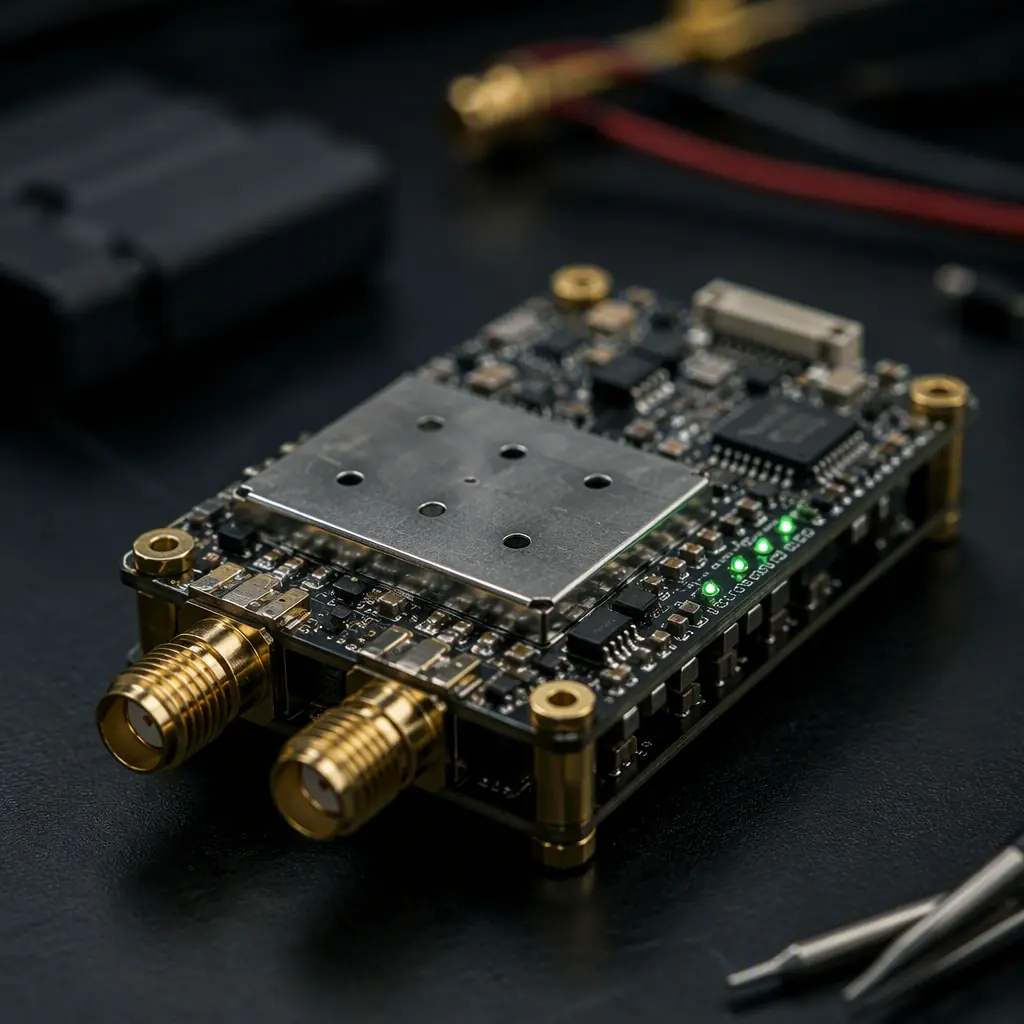
The mesh radio is the physical and link-layer foundation. Its job is to maintain a network where every node can reach every other node through one or more hops, and where the network heals when a node drops out — a UAV leaving the formation, or a link shadowed by terrain. The procurement-relevant parameters:
Topology. A true mesh is a peer-to-peer network: each aircraft can route traffic for its neighbors, and the ground station is just another node. The alternative — a star or a chain — is not a mesh, and the difference shows up in resilience: in a star, losing the hub aircraft kills the network; in a mesh, losing any single node reroutes the traffic. The specification should state the maximum hop count and the topology the radio supports (full mesh, partial mesh, or star with relay extension).
Protocol. The two realistic options are Wi-Fi-derived mesh (IEEE 802.11s, the mesh mode of 802.11) and dedicated mesh radio protocols. 802.11s hardware is cheap, commodity and well understood, with per-link data rates of tens to hundreds of Mbps at short range; its weaknesses are the CSMA/CA contention behavior under many nodes and the limited range of the 2.4/5 GHz ISM bands at UAV altitudes. Dedicated mesh radios — the defense and industrial segment — use proprietary or standards-derived waveforms (many are based on 802.11a/g with extensions, others on LTE-derived or custom PHYs) with features the Wi-Fi stack lacks: longer range, deterministic scheduling, better interference rejection and lower latency under load.
The data-rate/range trade. The mesh link budget follows the same physics as any RF link — the practical air-to-air range for a 100 mW class radio with modest antennas is roughly 1–3 km at 2.4 GHz and 0.5–1.5 km at 5.8 GHz, and the achievable throughput collapses with distance and hop count. A realistic planning number for a multi-aircraft mesh: a 10 Mbps aggregate mesh throughput at 1 km inter-aircraft spacing with 2 hops — enough for position/state exchange at 10 Hz and compressed imagery, not enough for full-rate video from every node simultaneously. The UAV communication protocols guide covers the lower-layer protocol landscape (CAN, DShot, SBUS, CRSF) that the mesh radio carries as payload — the mesh is the transport, and the avionics protocols ride on top of it.
 Concept illustration
Time synchronization: the requirement that makes a group a swarm
Coordinated maneuvers and distributed sensing fail without a common time base. A formation that must hold relative position to a meter needs position updates that are coherent in time; a distributed aperture or a synchronized camera array needs sampling across aircraft aligned to microseconds; a TDMA mesh needs slot boundaries that every node agrees on. The synchronization architecture has three tiers:
GNSS time. The receiver's 1 PPS output provides absolute time across the group to within tens of nanoseconds of UTC — the cheapest and most common synchronizing source, and the reason the GNSS module selection guide belongs in the swarm procurement conversation. The failure mode is the same one the GNSS anti-jamming and spoofing guide addresses: under jamming or spoofing, GNSS time becomes unreliable, and the swarm needs a fallback.
PTP/802.1AS over the mesh. Precision Time Protocol over the network synchronizes nodes to sub-microsecond accuracy when the link latency is stable and symmetric. The specification number is the time error budget: a realistic mesh PTP deployment holds 100–500 ns across two hops with a good radio; the budget must be tighter than the application's requirement by a margin of 3–5x.
Onboard holdover. Each aircraft's timing module — a TCXO or OCXO disciplined oscillator — maintains the local time base when the external reference drops. The spec is the holdover drift: a good TCXO drifts 0.5–2 ppm (roughly 0.5–2 µs per second), an OCXO holds 10–100 ppb. For a swarm that must keep microsecond coordination during a 60-second GNSS outage, the holdover oscillator choice is not a detail — it is the difference between staying coherent and losing the formation.
The timing architecture connects to the compute stack: the UAV edge AI and onboard computing guide covers the companion computers where the PTP stack, the sensor timestamping and the coordination logic run, and where timestamping quality is decided by the hardware clock architecture, not the software.
Frequency coordination: keeping N radios on the same spectrum without collision
Every additional aircraft adds a transmitter to the same spectrum, and the swarm problem is the interference problem multiplied. The coordination mechanisms, in increasing order of sophistication:
Static frequency planning. Each aircraft is assigned a channel or a time slot before launch, and the plan does not change in flight. Simple, cheap, and brittle — a jammer, an unexpected interferer or a lost node breaks the plan.
Dynamic channel selection. The radios sense the spectrum and hop or switch channels to avoid interference, including self-interference. The spec is the channel-switch latency and the coexistence algorithm: how the radio decides when a channel is degraded and how fast it moves.
TDMA scheduling. Time-division multiple access assigns each node a slot in a repeating frame, so N aircraft share one channel without colliding. The mesh radio's slot structure, the frame length and the slot guard time determine both the collision margin and the latency. A 10-node swarm with a 100 ms frame and 1 ms guard time gives each node a 10 ms slot — the timing discipline the communication protocols guide describes for avionics buses, applied to the radio link.
Spatial and polarization separation. Adjacent aircraft using different polarization or different spatial directions reduce co-channel interference without extra spectrum — the antenna-system layer below.
The regulatory side matters here: the 2.4 GHz band offers more bandwidth but more congestion, the 5.8 GHz band offers cleaner spectrum and shorter range, and the sub-GHz ISM bands (868/915 MHz) offer range at the cost of throughput. The certification implications of operating a mesh on licensed or unlicensed spectrum across borders are covered in the UAV component certification and compliance guide — a mesh radio's ETSI/FCC emissions compliance is per-device, but its frequency plan is per-operation.
 Concept illustration
Antenna systems for inter-UAV links: diversity, polarization and mounting
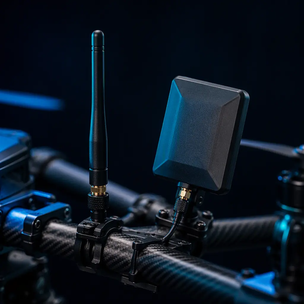
The mesh radio's range and reliability are decided by the antenna system, and multi-UAV operations stress it in specific ways. The first aircraft-to-aircraft reality is attitude: a UAV banking toward a neighbor rotates its antenna by tens of degrees, and a linearly polarized antenna that was aligned at the start of the maneuver is cross-polarized by the time the link matters most. The defenses are:
Polarization diversity. Two antennas with orthogonal polarization feeding the radio's diversity ports — the radio selects the stronger path. The gain is typically 5–15 dB of link margin in maneuvering flight, at the cost of a second antenna and a second RF path.
Spatial diversity. Antennas separated on the airframe (nose and tail, or wing tips) decorrelate the fading and the shadowing from the airframe itself — the carbon fiber structure and the payload block signals from specific directions.
Pattern and mounting. The antenna's radiation pattern must cover the directions the link actually uses — for an air-to-air mesh, that is the hemisphere around the aircraft, not the ground-facing pattern of a typical telemetry antenna. The mounting rule is the same one the RF communication systems guide documents for single-aircraft links: antennas clear of carbon fiber, away from the ESC current loops, and separated from each other by at least a quarter wavelength at the operating frequency.
The antenna count adds up fast on a swarm aircraft: GNSS, telemetry to ground, mesh radio, video downlink, Remote ID. The connectors, wiring and power distribution guide covers the RF cabling and the connector discipline — every additional antenna is additional cable loss, and the swarm aircraft's RF budget is the sum of all of them.
Onboard data distribution: what each node must carry
The mesh radio is the transport; the data that flows through it is generated and consumed by the onboard compute and payload stack. The swarm-specific requirements on each node:
State broadcast. Each aircraft broadcasts its position, velocity, attitude and intent (the next waypoint, the commanded maneuver) at a defined rate — 5–20 Hz is typical for coordinated flight. The message format and the latency budget must be specified, because the coordination algorithm's performance is bounded by the age of the state it receives.
Payload data routing. The sensor data (imagery, point clouds, detection results) must be routed to the node that needs it — the lead aircraft, the ground station, or the group — rather than broadcast to everyone. The mesh radio's multicast and routing support, and the onboard companion computer's data-management role, are the parts the edge AI and onboard computing guide covers from the compute side.
Local decision autonomy. The deeper design decision is how much coordination runs on the aircraft versus the ground. A swarm that requires the ground station to arbitrate every maneuver has a single point of failure at the ground link; a swarm where the aircraft exchange state directly and run the coordination algorithm onboard keeps flying when the ground link degrades. The specification should state the autonomy boundary — which decisions are onboard and which require ground confirmation — because it determines the mesh traffic pattern, the onboard compute requirement and the safety case.
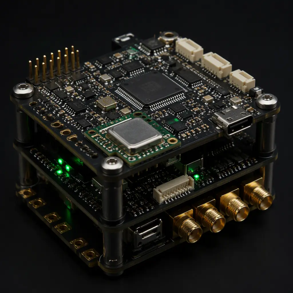
The research and development components guide covers the open-architecture flight controllers and the configurable payloads that most swarm programs start from — the first swarm prototype is usually five research aircraft with mesh radios bolted on, and the production spec is written from what that prototype proves.
 Concept illustration
Ground control integration: tracking, handover and the network view
The ground control station (GCS) is a network node with special responsibilities: the operator's view of the swarm, the link to the outside world, and — for most non-defense operations — the source of command authority. The ground control station hardware guide covers the single-aircraft GCS stack; the swarm adds three requirements:
Multi-aircraft tracking. The GCS must display and manage N aircraft simultaneously — position, state, link quality and payload status for each — with the same UI discipline that prevents the operator from confusing one aircraft for another. The spec is the GCS software's supported aircraft count and the state-update handling at the mesh rate.
Network visualization. The operator needs the mesh topology, not just the aircraft: which links are up, which hop counts the traffic is taking, which node is carrying the routing load. A mesh that is healthy at the node level can still be operationally broken if the topology has silently degraded to a chain.
Handover and recovery. The GCS procedures for losing a node — reassigning its mission to a neighbor, routing around the gap, recalling the aircraft — are the operational expression of the mesh resilience. The public safety components guide and the logistics and delivery components guide document how these procedures are specified for the two operator classes that will deploy swarms first: search and rescue, and delivery networks.
 Concept illustration
The RFQ checklist: 12 line items for swarm-capable communication hardware
The following line items translate the swarm communication stack into an RFQ-ready specification. They apply to the complete communication subsystem — the mesh radios, the antennas, the timing modules and the onboard integration — and each item names the evidence the supplier should provide.
1. Operating mode statement. The RFQ states the mission type — independent, relayed or true swarm — and the aircraft count, the spacing and the data requirements. Verification: the supplier's architecture response matched to the stated mode.
2. Mesh topology support. The radio shall support full-mesh peer routing with a stated maximum hop count (e.g., 4 hops) and automatic rerouting on node loss. Verification: the radio's routing documentation and a multi-node bench test log.
3. Link budget and range. The air-to-air range and the throughput at the required spacing, stated with the antenna configuration and the power class. Verification: the range test report at the specified geometry.
4. Data rate and latency. The per-link and aggregate mesh throughput, and the end-to-end latency at the specified hop count. Verification: the throughput/latency measurement at the specified node count.
5. Time synchronization. The mesh shall hold the stated synchronization accuracy (e.g., 500 ns across 2 hops) with GNSS-time, PTP and holdover modes. Verification: the sync accuracy measurement and the holdover drift specification.
6. Frequency coordination. The radios shall support the required coordination mechanism — fixed plan, dynamic channel selection or TDMA scheduling — with the channel-switch latency stated. Verification: the coexistence test record.
7. Spectrum and certification. The radios shall meet the emissions and certification requirements of the operating regions (FCC/ETSI per device). Verification: the certification documents for the delivered hardware revision.
8. Antenna system. The aircraft shall carry the antenna configuration (polarization or spatial diversity) required for the link budget, with the mounting documented. Verification: the antenna placement drawing and the measured pattern.
9. Onboard integration. The mesh radio and the timing module shall interface with the specified flight controller and companion computer, with the state broadcast rate and the message format defined. Verification: the interface control document and an integration test log.
10. Autonomy boundary. The RFQ states which coordination decisions run onboard versus ground-confirmed. Verification: the supplier's system architecture response and the fallback behavior on ground-link loss.
11. Ground control integration. The GCS shall support the required aircraft count with multi-aircraft tracking, topology visualization and handover procedures. Verification: the GCS software spec and a multi-node demonstration.
12. Test evidence and traceability. The supplier shall provide the multi-node test methodology, the recorded results for the delivered serial numbers and the firmware version control. Verification: the delivery documentation package.
The surrounding subsystems complete the picture: the defense and security components guide covers the encrypted-link and anti-jam requirements that a military swarm imposes on the same stack, and the communication protocols guide ties the onboard protocols to the radio transport.
Explore custom engineering Back to Blog
Continue Reading
UAV RF Communication Systems Guide
The single-aircraft link stack — telemetry, control and video — that the mesh layer extends to multiple aircraft.
UAV Communication Protocols: CAN, DShot, PWM, SBUS, CRSF
The onboard avionics protocols that ride on top of the mesh transport.
UAV Edge AI & Onboard Computing
The companion computers where the coordination logic, the PTP stack and the sensor timestamping run.
UAV Ground Control Station Hardware
The single-aircraft GCS stack, extended to multi-aircraft tracking and network visualization.
UAV Defense & Security Components
Encryption and anti-jam requirements for military swarms on the same communication stack.