

Every UAV navigation conversation starts with GNSS and most end with an accuracy number — centimeters with RTK, meters with a standalone receiver. The contested-spectrum conversation starts with a different question: what happens to the aircraft when the GNSS signal is not degraded but deliberately attacked? The attack surface is real and measurable. Portable jammers rated at 10 W can blanket L1 at ranges of hundreds of meters to kilometers, and GPS spoofing demonstrations have steered drone autopilots off course with nothing more than a $500 transmitter. For defense, public safety, UTM-enabled BVLOS and logistics platforms, GNSS resilience is now a written procurement requirement, not a nice-to-have. This guide covers the five defense layers you can actually specify — antenna, front end, receiver, inertial backup and detection — and the procurement evidence that proves a supplier's claims.
Jamming vs spoofing: the two threat models and their signatures
The two attacks are often discussed together, but they target different vulnerabilities and require different countermeasures. Jamming is a denial-of-service attack: the attacker transmits noise or continuous wave energy on the GNSS bands, raising the noise floor until the receiver can no longer lock the satellite signals. A typical GPS L1 signal arrives at the antenna at roughly −130 dBm; a jammer that lifts the noise floor by 30 dB destroys the carrier-to-noise ratio (C/N0) margin for every receiver in range. Jamming is easy to detect — the C/N0 values collapse across all satellites simultaneously — and the consequence is a loss of position, usually with the aircraft still under manual or inertial control.
Spoofing is a deception attack: the attacker transmits counterfeit satellite signals that the receiver locks onto and tracks as genuine. The receiver then computes a position chosen by the attacker — a few meters offset to push a survey drone off line, or a few kilometers offset to redirect a delivery aircraft. The dangerous part of spoofing is that the receiver reports a healthy fix: C/N0 looks normal, the constellation looks normal, and the navigation output is confidently wrong. Detection requires receiver-internal checks — clock jump monitoring, ephemeris validation, C/N0 anomaly signatures, and cross-checks against inertial and other sensors.
The two threats also differ in cost and legality. Jammers are cheap, widely available and banned in most jurisdictions, but enforcement is rare and incidents are common. Spoofing requires more engineering but the hardware is commodity. Both attacks are now regular enough that the UAV defense and security components guide treats GNSS resilience as part of the baseline contested-spectrum stack, and the UTM and detect-and-avoid integration guide covers how degraded navigation feeds into the BVLOS safety case.
 Concept illustration
The antenna layer: CRPA and the difference between gain and pattern control
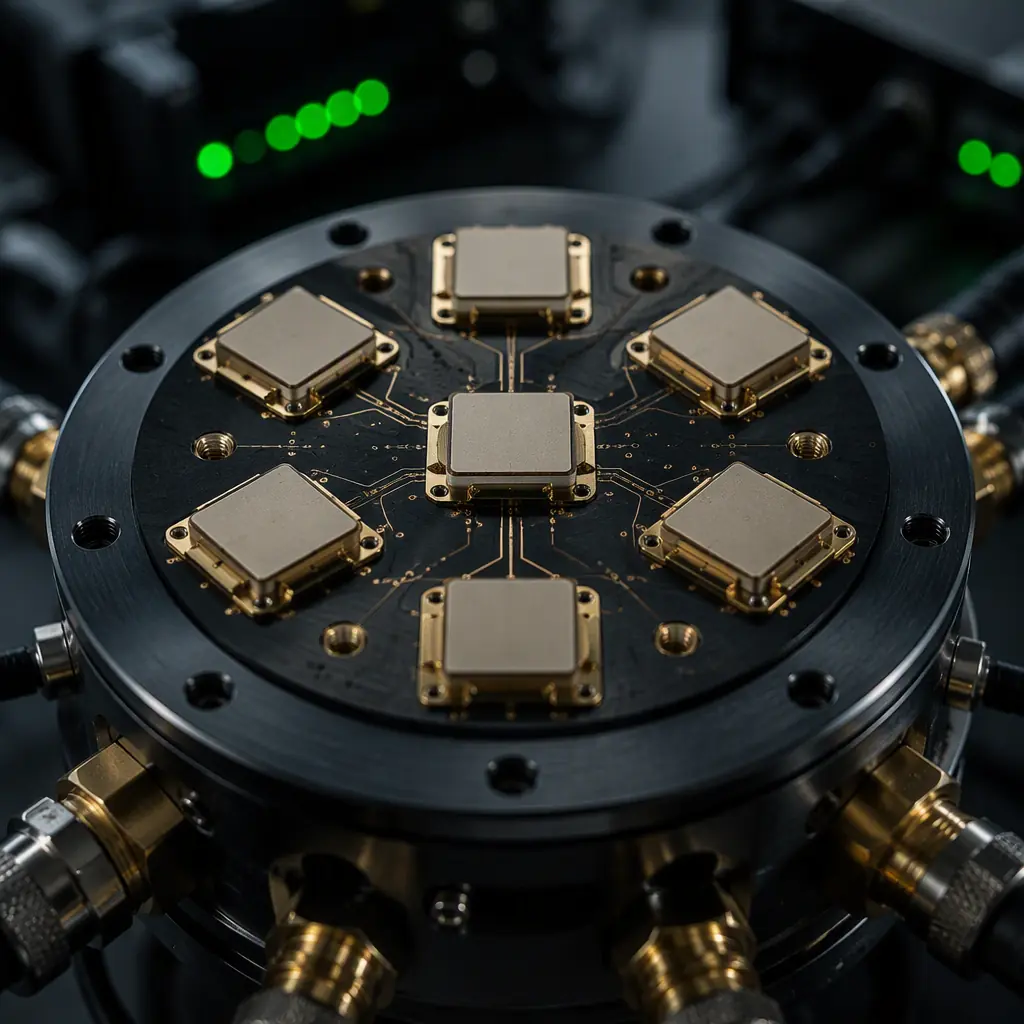
The first defense is at the antenna, before the RF energy reaches the receiver. A conventional GNSS antenna is a single patch element with a hemispherical gain pattern — it receives the sky and the jammer equally. A CRPA (controlled reception pattern antenna) is an array of elements whose outputs are weighted so that the antenna pattern places nulls in the direction of interference sources while maintaining gain toward the satellites. The practical specification numbers that matter in procurement:
Number of elements. A 4-element CRPA can place one to three nulls; a 7-element array (the common defense-grade configuration) handles more simultaneous interferers and produces deeper, more stable nulls. More elements mean more weight, more power and more cost — a 7-element array with its electronics adds roughly 150–400 g and 2–5 W to the aircraft, which is why the element count must be matched to the threat model, not maximized.
Null depth and width. Defense-grade CRPAs typically specify 20–30 dB of null depth with a beamwidth of 20–40 degrees per null. A 25 dB null reduces a jammer's effective power by a factor of 300 at the receiver input — the difference between losing lock and maintaining a degraded fix.
Anti-jam gain and the J/N budget. The antenna system's anti-jam performance is usually quoted as the jamming-to-noise ratio (J/N) at which the receiver still maintains lock, or as the jammer power density the system survives. A useful procurement benchmark: a modern anti-jam antenna plus receiver combination should maintain position across a 60–80 dBJ J/N budget against continuous wave and narrowband jammers, versus roughly 30–40 dBJ for an unprotected receiver with a good front end.
The GNSS module selection guide covers the receiver-side choices — constellation support, multi-band architecture and RTK accuracy — while this article focuses on the resilience layer that sits in front of the receiver. The two specifications must be read together: an RTK-grade receiver behind a poor antenna is still jam-vulnerable, and an anti-jam antenna feeding a single-band receiver leaves the L2/L5 bands unprotected.
RF front-end hardening: filtering, LNA saturation and the interference budget
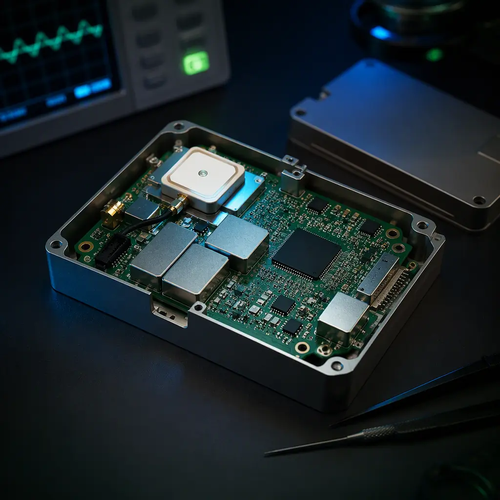
Between the antenna and the receiver's correlators sits the RF front end — the filters, low-noise amplifiers (LNAs), mixers and the ADC that conditions the signal. This is the layer where a cheap design fails first under attack. The failure mode is desensitization: a strong in-band jammer saturates the LNA or the ADC, and the receiver's noise figure collapses even if the jammer is later filtered. The procurement-relevant defenses:
Out-of-band filtering. SAW filters and dielectric resonator filters reject the strong out-of-band transmitters that share the RF environment — cellular bands, 2.4 GHz ISM, FM broadcast — before they reach the LNA. The spec is the filter rejection (typically 40–60 dB at 50–100 MHz offset from the GNSS band edge) and the insertion loss in-band (below 2 dB).
LNA linearity and headroom. A hardened front end uses LNAs with high IP3 (third-order intercept) and enough dynamic range to survive moderate jammers without saturation. The measurable outcome is the 1 dB compression point and the ADC headroom — typically 14–20 dB of margin above the expected signal-plus-noise floor, which lets the receiver keep processing through interference that a marginal design would clip.
Jamming-to-noise budget in the spec. The most useful single procurement number is the receiver's stated J/N tolerance: the ratio of jammer power to noise power at the antenna port at which the receiver maintains a defined level of performance (e.g., position accuracy within 10 m, or time-to-first-fix under 60 s). Suppliers who quote this number have designed for it; suppliers who quote only sensitivity have not.
Front-end hardening interacts with the rest of the avionics environment — the EMC/EMI design and compliance guide covers how the GNSS front end coexists with the ESC switching noise, the video transmitters and the telemetry radios on the same airframe, which is where most real-world desensitization actually originates.
Receiver-internal defenses: RAIM, multi-constellation and spoofing detection
The receiver itself carries the second and third lines of defense. The first is RAIM (receiver autonomous integrity monitoring) with fault detection and exclusion (FDE): the receiver continuously checks the consistency of the pseudorange measurements and can detect and exclude a failing satellite. RAIM is a baseline requirement for aviation-grade navigation and catches the accidental failures — a failed satellite, a bad ephemeris — but it is not a spoofing defense by itself, because a sophisticated spoofer makes all the measurements consistent with the false position. RAIM becomes useful against spoofing when the attacker makes errors: the transition from genuine to spoofed signals usually produces measurable discontinuities.
The second is multi-constellation, multi-band reception. A receiver that tracks GPS, GLONASS, Galileo and BeiDou across L1/L2/L5/E1/E5 bands is dramatically harder to jam or spoof completely, because the attacker must cover more spectrum with more power and more precision. A single-band L1-only receiver can be defeated by one narrowband jammer; a dual-band receiver forces the attacker to jam two bands; a tri-band receiver with four constellations forces the attacker to replicate the entire multi-constellation signal environment coherently — a problem that is orders of magnitude harder than replaying one band.
The third is spoofing detection logic, which lives in the receiver firmware and reports a navigation integrity flag rather than silently continuing. The detection metrics that appear in real products:
- Carrier-to-noise anomalies. All satellites suddenly showing identical or suspiciously flat C/N0 — a signature of a single spoofer broadcasting from one location — triggers a warning.
- Clock and NCO jumps. A sudden receiver clock jump or a discontinuity in the numerically controlled oscillator output indicates a handover from genuine to spoofed signals.
- Ephemeris and almanac validation. Comparing broadcast ephemeris against known constellation data; a mismatch flags the source as suspect.
- Cross-band and cross-constellation consistency. The position computed from L1 must agree with the position from L5; disagreement indicates band-specific interference or spoofing.
- Inertial cross-check. The GNSS position compared against the integrated inertial solution — a spoof that drags the position away while the accelerometers and gyros see no corresponding motion is detectable within seconds.
The receiver output that matters for the rest of the aircraft is not just the position but the integrity status: a receiver that reports "degraded — inertial hold" instead of a confidently wrong position is what lets the flight controller execute a safe fallback. The sensor fusion and redundant navigation guide covers how the flight controller arbitrates between GNSS, IMU, barometer, magnetometer and vision inputs when the GNSS integrity flag drops.
 Concept illustration
The IMU fallback: how long the aircraft can navigate without GNSS
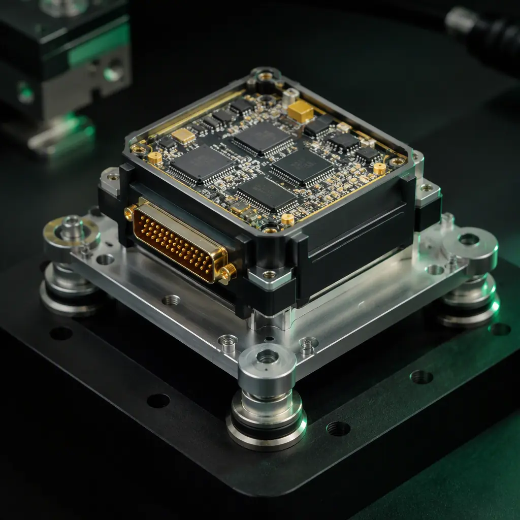
Every anti-jam specification eventually meets the same arithmetic: the antenna and front end extend how much jamming the receiver survives, but a determined attacker with enough power will eventually win. The platform-level answer is the navigation fallback — the sensors that keep the aircraft safe when GNSS is gone. The quality of the fallback is defined by the inertial sensor grade and the fusion architecture:
Consumer MEMS IMUs (the class in most commercial flight controllers) drift at rates of several degrees per minute and tens of meters of position error within seconds to a minute of GNSS loss — they are fine for attitude hold, not for navigation. Industrial/tactical MEMS IMUs (bias stability in the single-digit deg/hr range) hold a usable position for minutes. Navigation-grade sensors (fiber-optic or high-end ring-laser gyros, 0.01–0.1 deg/hr) can navigate for tens of minutes, but they cost more than most UAVs and are not a realistic component for the commercial segment.
The realistic procurement position for a commercial or public-safety platform is: a tactical-grade MEMS IMU plus the fusion of whatever auxiliary measurements exist — the barometer for altitude, the magnetometer for heading, optical flow or visual odometry for velocity, and UWB or range measurements where a ground anchor network exists. The sensor fusion and redundant navigation guide details the arbitration and the Remote ID and BVLOS components guide covers the regulatory side — most BVLOS waivers now require the operator to demonstrate a defined degraded-navigation response, and the IMU grade is the first number the authority asks for.
The specification to write is not "has an IMU" but a degraded-navigation time: "the aircraft shall maintain a position error of less than 50 m for 5 minutes after total GNSS loss, using inertial and onboard sensors alone." That single sentence forces the supplier to make the IMU grade, the fusion algorithm and the antenna resilience choices explicit — and it is testable in a jam-box trial.
 Concept illustration
Detection and mitigation: the strategy that turns resilience into procedure
The defense layers above make the aircraft harder to attack; the detection layer decides what the aircraft does when the attack happens. A complete GNSS resilience strategy has three phases, and the component specification should name all three:
Detect. The receiver's integrity flags (C/N0 collapse, clock jump, cross-constellation inconsistency) plus an optional dedicated jamming detector — a small spectrum-monitoring front end that measures the noise floor in the GNSS bands and reports a jamming-to-noise estimate to the flight controller. The output is an event: "GNSS under attack, integrity invalid."
Mitigate. The flight controller switches the navigation source — from GNSS-aided to inertial/vision-aided navigation, holds altitude and heading, and either continues the mission within the degraded-navigation envelope or executes a pre-programmed return-to-launch. The public safety components guide covers the operational side of this decision: for a search-and-rescue platform the procedure may be "hold position and loiter," while for a delivery platform it is usually "return to launch immediately."
Report. The aircraft records the attack event — the timing, the C/N0 profile, the detected jammer direction if the CRPA provides it — and transmits the log with the telemetry. For defense and law-enforcement operators this record is often as valuable as the aircraft itself, and it is the evidence that justifies the anti-jam budget on the next program.
The mitigation behavior is specified at the flight controller level, and the ArduPilot vs PX4 guide is a useful reference for how each open-source stack exposes GNSS integrity to the mission logic — both support EKF-based GNSS/inertial fusion and both expose the innovation/health parameters that a jamming-detection watch can monitor.
 Concept illustration
Testing anti-jam performance: the jam-box trial and what to measure
Anti-jam performance is one of the most over-claimed specifications in UAV components, because it is hard to test and easy to hand-wave. The procurement team should not accept a datasheet line; it should specify a test. The standard approach is a jam-box trial: the aircraft or the receiver under test is placed in an RF-shielded chamber (or an open-field range with controlled emissions), a signal generator injects jamming at defined power levels and frequencies, and the receiver's behavior is recorded. The measurement points that belong in the acceptance test:
- J/N at loss of lock. The jamming-to-noise ratio at which the receiver loses position — the headline anti-jam number.
- Time to re-acquire. How quickly the receiver re-locks after the jammer is removed — a receiver that takes 5 minutes to re-acquire is operationally useless even if it survives a strong jammer.
- Spoofing detection latency. How long the receiver takes to flag a spoofing attack — the target is under 10 seconds for a platform that will maneuver.
- Degraded-navigation accuracy. The position error growth over the specified GNSS-denied period, measured against a truth reference.
- Multi-threat scenarios. Continuous wave, swept, chirp and pulsed jamming across the band plan, plus combined jamming-plus-spoofing — the realistic attack.
The UAV propulsion testing and validation guide covers the general testing framework for UAV components — the same discipline of specified inputs, recorded outputs and pass criteria applies to RF resilience. A supplier that offers a documented jam-box report for its GNSS stack is a different procurement category from a supplier that offers a brochure.
The RFQ checklist: 12 line items for specifying GNSS resilience
The following line items translate the defense layers into an RFQ-ready specification. Each item names the evidence the supplier should provide, and the checklist works for a complete GNSS stack, a standalone anti-jam antenna or a receiver upgrade.
1. Threat model statement. The RFQ states the design basis: the jammer power levels, the frequency bands and the spoofing sophistication the platform must survive. Verification: the supplier's threat-model response and the architecture that follows from it.
2. Anti-jam antenna architecture. Element count, null depth (≥20 dB recommended for the defense tier), null steering method (analog vs digital beamforming) and the mass/power budget. Verification: the antenna datasheet and the pattern measurements.
3. J/N tolerance. The receiver shall maintain position at a stated J/N (e.g., 70 dBJ against narrowband continuous-wave jamming). Verification: the jam-box test report.
4. Front-end headroom. LNA IP3, ADC dynamic range and out-of-band filter rejection specified numerically. Verification: the front-end test data.
5. Constellation and band plan. The receiver shall track the constellations and bands required for the operating region — minimum dual-band, quad-constellation for defense and BVLOS tiers. Verification: the receiver's tracking specification and a recorded skyplot.
6. RAIM/FDE. The receiver shall implement RAIM with fault detection and exclusion, with the protection-level output exposed. Verification: the receiver interface document and a test log showing an excluded satellite.
7. Spoofing detection. The receiver shall detect spoofing within 10 seconds and raise a navigation integrity flag. Verification: the spoofing-detection test record with the detection latency.
8. Integrity output. The receiver shall expose a machine-readable integrity status (not just a position) to the flight controller. Verification: the interface control document and a signal trace showing the flag transition under attack.
9. Inertial fallback. The aircraft shall maintain a position error below 50 m for 5 minutes after total GNSS loss. Verification: the GNSS-denied trial record against a truth reference.
10. Re-acquisition. Time to re-acquire position shall be under 60 seconds after jammer removal. Verification: the jam-box re-acquisition measurement.
11. Environmental rating. The antenna and receiver shall meet the platform's operating temperature, vibration and IP requirements, and the CRPA mounting shall not interfere with the airframe's other antennas. Verification: the environmental test reports and the antenna placement study.
12. Test evidence and traceability. The supplier shall provide the jam-box test methodology, the recorded results for the delivered serial numbers and the firmware version control for the receiver. Verification: the delivery documentation package.
The component selection context for the rest of the navigation and communication stack is covered in the GNSS module selection guide and the UAV RF communication systems guide — the antenna placement and the RF coexistence decisions are made together, not separately.
Explore custom engineering Back to Blog
Continue Reading
UAV GNSS Module Selection Guide
The receiver-side decisions — constellation support, multi-band architecture, RTK vs PPK accuracy tiers — that the resilience layer protects.
UAV Sensor Fusion and Redundant Navigation
How the flight controller arbitrates between GNSS, IMU, barometer and vision when the GNSS integrity flag drops.
UAV Defense & Security Components
The contested-spectrum stack — encrypted links, anti-jam navigation and ruggedization — as a single procurement picture.

UTM and Detect-and-Avoid Integration
How degraded navigation feeds into the BVLOS safety case and the UTM compliance architecture.

UAV Public Safety Components
The operational mitigation procedures — loiter, return-to-launch, report — that the detection layer triggers.