
Why boom stiffness is a procurement decision
On almost every multirotor, the arms and booms are the last structural element to get engineering attention and the first to cause a flight fault. They are also the element most often bought as stock material, by diameter, from a catalogue, with no stiffness requirement attached. That is a mismatch: the boom sets the aircraft's structural bandwidth, its vibration signature and its payload pointing accuracy, and all three of those are determined by numbers that appear on a purchase order.
The airframe materials guide covers which material family to choose; this guide covers how to specify the tube once carbon fiber is the answer.
Two construction families: pultruded and roll-wrapped
Almost every carbon fiber tube sold into the UAV market is one of two things, and the choice between them drives the whole specification. Understanding the difference early saves the common failure of ordering a tube by outer diameter alone and discovering the stiffness was never in the diameter.
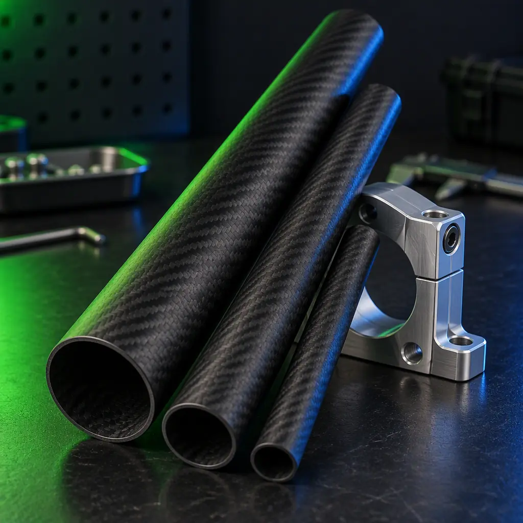
Pultruded tubes. Continuous fibre tows are pulled through a die with the fibre running axially, then cured. The result is a tube with very high axial stiffness and strength at the lowest cost per metre, which is why it dominates arms and booms on 5- to 25-inch-class multirotors. The trade-off is anisotropy: pultruded tube is stiff along its length and comparatively weak in torsion and hoop (crush) loading, because there are few off-axis fibres. Pultruded stock comes in fractional-inch and metric sizes, typically 8 mm to 50 mm outside diameter, with wall thicknesses from 0.5 mm to 3 mm, and because it is die-drawn the wall is uniform to a few hundredths of a millimetre and the finish is a smooth matte black with visible axial fibre lines.
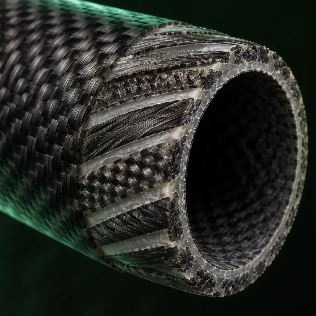
Roll-wrapped tubes. Prepreg or resin-impregnated fabric is wrapped around a mandrel in plies at controlled angles, then vacuum-bagged and oven- or autoclave-cured. Because the fibre orientation is a design variable per ply, a roll-wrapped tube can be built with a 0-degree layer for bending stiffness, a 45-degree layer for torsion and crush, and a 90-degree hoop layer to resist clamp loads. Roll-wrapped tube is the correct choice when a boom carries torsional load, when a clamp will crush a pultruded tube, or when the tube is also a stressed member of a wing spar. It costs two to four times pultruded per metre and needs tooling for a custom layup, but for anything above roughly a 15 kg take-off mass the anisotropy of pultruded tube usually becomes the limiting factor.
A practical decision rule used across the industry: below about 5 kg take-off mass, pultruded tube is almost always sufficient; between 5 and 25 kg the choice depends on whether torsion or clamp loads dominate; above 25 kg, design a roll-wrapped layup and treat the tube as an engineered part, not stock material. The airframe structural design guide covers where the load paths run once the tube is in the frame.
Sizing by stiffness, not by wall thickness
The most common mistake in boom procurement is specifying a wall thickness. Wall thickness is an output, not an input: it falls out of the stiffness the aircraft actually needs. The governing quantity for a cantilevered boom is bending stiffness, the product of the material's elastic modulus and the tube's second moment of area, and that second moment of area scales with the fourth power of diameter and only linearly with wall thickness. Doubling wall thickness doubles stiffness; increasing diameter by 26 percent does the same thing. This single relationship explains why long-endurance airframes run large-diameter thin-wall booms rather than small thick ones.
For a round tube, the second moment of area is approximately I = pi x D cubed x t / 8 for thin walls, where D is the mean diameter and t the wall. Take a 20 mm outside diameter, 1 mm wall pultruded tube with a typical axial modulus of 100 GPa. Its second moment of area is about 785 mm^4 and its bending stiffness about 78.5 N.m squared. Move to a 25 mm outside diameter, 1 mm wall tube and the second moment of area rises to about 1,530 mm^4, nearly doubling the stiffness at the same wall thickness and a weight increase of only 25 percent. Move instead to a 20 mm tube with a 2 mm wall and stiffness also doubles, but the mass rises 100 percent. Diameter is the cheaper lever every time.
The target that matters in flight is not a stiffness number, it is a frequency. A boom must be stiff enough that its first bending mode sits well clear of the rotor and control-loop frequency band. As a working rule, keep the first cantilever bending mode of a loaded boom at least three times the highest blade-pass frequency, which on a 600 mm boom with a 1 kg tip mass works out to a first mode above roughly 60 Hz. Below that margin the boom acts as a resonant amplifier for motor vibration and gyroscopic precession, and the flight controller fights an oscillation it cannot tune out. Specifying the mode target, not the wall, is what lets a supplier choose the cheapest tube that works.
 Roll-wrapped ply stack
Fibre orientation and the crush problem at clamps
If pultruded tube fails in service, it almost never snaps in bending. It crushes, ovalises or splits at the point where a clamp bolts it to the frame. Axial fibre carries no hoop load, so a clamp that is tightened to hold the boom against thrust also compresses the tube wall with nothing resisting it, and the tube deforms into an oval. Once ovalised, its second moment of area drops and its stiffness collapses locally, which is how a boom that tested stiff on the bench fails in flight.
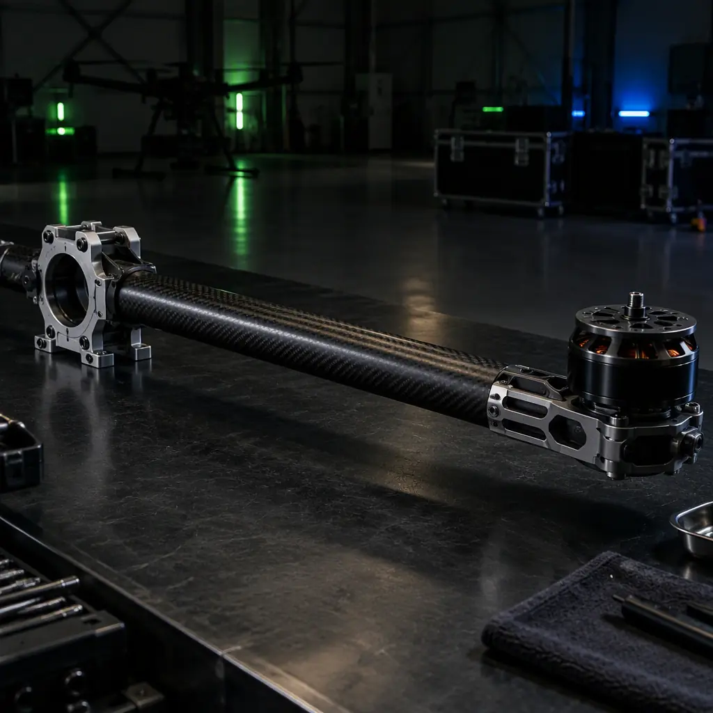
The fixes are unglamorous and effective. Use a clamp that spreads load over at least 1.5 tube diameters of length rather than a narrow clip. Specify a wall thick enough that hoop stress at the clamp stays below roughly a quarter of the transverse compressive strength; on 20 mm pultruded tube with 1 mm wall this in practice means clamping over 25 to 30 mm of length with a saddle-style clamp, not a cable tie or a single bolt ear. Where a roll-wrapped tube is used, insist on at least two hoop plies in the clamp region so the wall can take the bolt preload without ovalising. And never drill a pultruded boom on its neutral axis for cable routing without reinforcing the hole: a bare hole through axial-fibre tube is a stress concentration with no hoop fibre to arrest the split.
 Boom, saddle clamp and motor mount
For booms that see torsion, such as those carrying a gimbal or a rotating payload, the layup must include plus-or-minus 45-degree plies. A purely axial tube twisted under load warps and loses pointing accuracy, and no amount of diameter fixes it; the fibres simply have nothing to shear against. The vibration isolation guide explains how the resulting boom motion propagates into payload pointing error.
Tube-to-frame joints: inserts, bonding and the load path
The joint between a boom and the airframe centre plate is where the boom's stiffness either transfers into the structure or terminates in a soft, creeping connection. There are three common joint families, and each has a characteristic failure.
- External saddle clamps. The boom sits in a machined saddle and is pinched by two or more bolts. Cheap, reusable and adjustability-friendly, this is the default on folding arms. Its weakness is clamp pressure and slip: under repeated landing shock the boom creeps in the saddle and the arm angle drifts. Verifying the joint means specifying bolt preload and checking arm-angle repeatability after a hundred landing cycles.
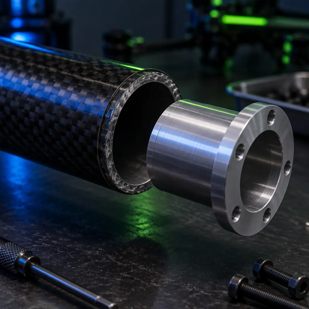
- Internal inserts. A machined aluminium or titanium insert is bonded inside the tube bore and bolts through the frame, so the load path is axial inside the tube rather than clamping around its outside. This is the strongest joint per gram and the one used on heavy-lift arms. Its failure mode is bond-line shear: an unbonded or partially bonded insert pulls straight out under tensile load. Specifying insert pull-out strength, not just insert material, is what makes this joint trustworthy.
- Bonded sleeves and scarf joints. A tube is telescoped into a larger sleeve or scarfed and bonded for continuous booms and wing spars. The joint can approach parent-material strength but is permanent and sensitive to bond-line thickness and surface preparation. Grit-blast and solvent-wipe preparation, plus a controlled adhesive gap, are process requirements that belong in the purchase order, not assumptions.
Whichever family is used, the load path question is the same: does the joint carry the bending moment in tension and compression through the tube wall, or does it rely on friction? Friction-based joints creep and lose preload; bonded and bolted-through joints do not, provided the bond or the insert is specified by strength. The assembly tooling and fixtures guide covers the jigs that make these joints repeatable in production.
 Bonded insert joint
Verifying a boom before it flies
A boom specification is only as good as the test that proves it. Three checks separate a tube that works from a tube that merely looks right, and all three are cheap enough to require from a supplier.
Static stiffness and deflection test. Load the assembled boom at the tip with the design thrust and inertial load, measure tip deflection and compare it to the predicted value. A boom that deflects more than the analysis predicted has a joint problem, not a tube problem, and finding that on the bench is far cheaper than in flight. Record deflection against load and check linearity: a joint that creeps shows as a curve that never returns to zero.
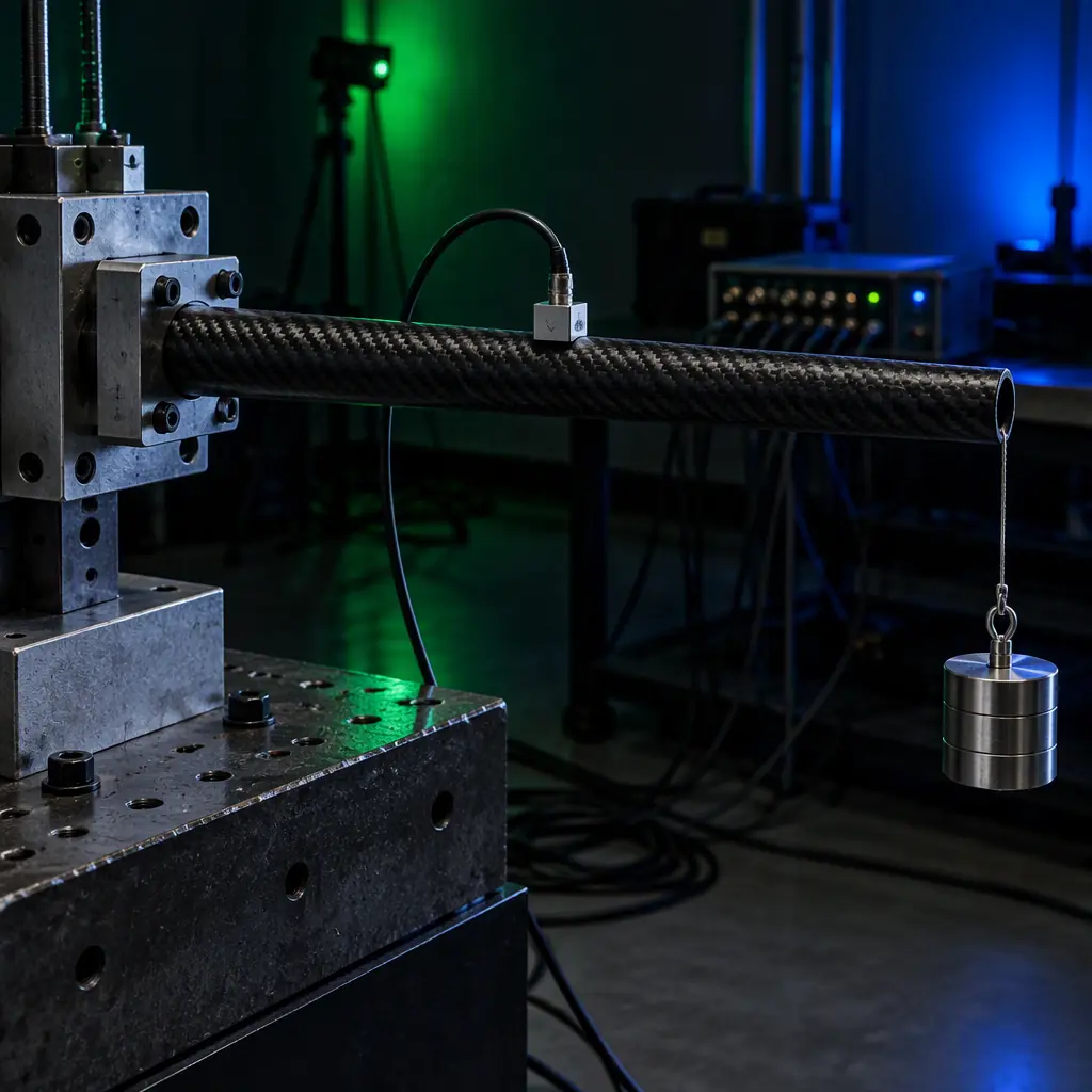 Deflection and modal test rig
Modal and vibration test. Mount the loaded boom, excite it and measure the first bending mode with an accelerometer. The measurement confirms the mode target used in sizing. If the measured mode sits inside the rotor band, the boom needs more diameter and the design cycle repeats before anything is built. The propeller balancing and vibration guide covers the excitation-side reduction that halves the problem.
Joint strength and cycle test. Pull the insert or clamp to its specified proof load, then cycle the joint through the landing-shock and thrust-cycle envelope and re-measure slip and preload. A joint that passes the proof load but loosens over 500 cycles is a maintenance liability. The environmental qualification testing guide extends this to temperature and humidity, which swell and plasticise the resin and change bond-line behaviour.
Ask for the raw deflection-versus-load and mode data with the shipment, not a summary sheet. A supplier who measured a boom can produce the curve; one who did not will send a compliance sentence.
Cost, lead time and the buy decision
Carbon fiber tube is a commodity in pultruded form and an engineered part in roll-wrapped form, and the commercial terms reflect that split. Pultruded tube in common diameters ships from stock with lead times measured in days, and the cost is driven almost entirely by diameter and wall. Roll-wrapped custom layups carry tooling or mandrel costs and lead times of two to six weeks depending on cure route and layup complexity, which is why a first article should be ordered as a prototype quantity before committing to a production volume.
Where cost pressure bites is at the joint. Bonded inserts, machined clamps and saddle hardware often exceed the cost of the tube itself, so a design that selects a cheaper pultruded tube but then adds heavy hardware to protect it from clamp crush frequently costs more than a roll-wrapped tube with a low-part-count integral joint. The total-cost comparison should always be made on the assembled boom, not the tube alone, which is the same discipline the build-versus-buy analysis applies to subsystems.
Finally, tolerances belong in the order. Outside diameter runout, wall uniformity, straightness and cut-length tolerance all affect how a boom fits a clamp or seats in a frame. A straightness specification of 0.5 mm per 500 mm is a normal aerospace-grade requirement for a boom and costs little to hold; leaving straightness unspecified is how a set of arms arrives with mismatched tracking angles.
Procurement checklist: what to put in the RFQ
Six data points convert a boom order from a stock-diameter guess into a specification the supplier can design against.
- 1. Load case and tip load. The mass at the boom tip, the design g-load and the thrust the arm carries, with the unsupported length between the frame joint and the tip. This is the input to every stiffness calculation and the single most useful number you can send.
- 2. Stiffness or mode target. Either a minimum bending stiffness in newton-metres squared or, more practically, a minimum first bending mode in hertz for the loaded boom. Given this, a supplier can size diameter and wall rather than quoting a stock tube.
- 3. Construction and layup. Pultruded stock or a specified roll-wrapped layup with hoop and off-axis plies where clamps and torsion demand them. State whether the tube is purely a boom or also a torsional member.
- 4. Joint type and insert strength. Saddle clamp, bonded insert or bonded sleeve, with insert pull-out strength and clamp length specified. Include bolt size and preload if the frame interface is fixed.
- 5. Environmental range. Operating temperature, UV exposure and humidity, and whether the tube sees chemical or salt exposure. Resin systems and finishes differ, and a boom that works in a desert may embrittle in a cold maritime environment.
- 6. Test data required. Deflection-versus-load, measured first mode, joint proof and cycle data, straightness and dimensional report. Verification: the raw test records, delivered with the shipment.
The decision, in one line: choose pultruded for light axial booms and roll-wrapped where torsion or clamp crush governs, size the tube by bending stiffness and mode target rather than wall thickness, design the joint before the tube, and demand the deflection and mode data in the RFQ. EMS Drone supplies carbon fiber tubes, machined inserts, clamps and bonded-joint assemblies, and runs the stiffness and modal testing that proves a boom before it flies. Send the tip load, the unsupported length and the mode target, and we will respond with the tube specification, the joint design and the test plan.
Explore airframe capability Back to Blog
EMS Drone manufactures airframe structures and boom assemblies under one roof, from tube sourcing through bonded-joint production and modal test. If you are specifying a boom, see the custom engineering service and the tolerances we hold.
Continue Reading
UAV Airframe Materials Guide
Which material family to choose before you pick a tube: carbon, aluminium, G10 and the trade-offs between them.
UAV Airframe Structural Design
Stiffness, modes and load paths, the analysis that turns a boom choice into a verified structure.
UAV Vibration Isolation
Mounts that protect payloads from the boom and motor vibration a stiffer structure cannot remove.
UAV Assembly Tooling and Fixtures
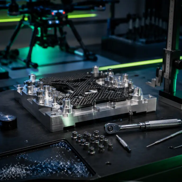
The jigs that make bonded tube joints and arm geometry repeatable across a production run.
UAV Composite NDT Inspection
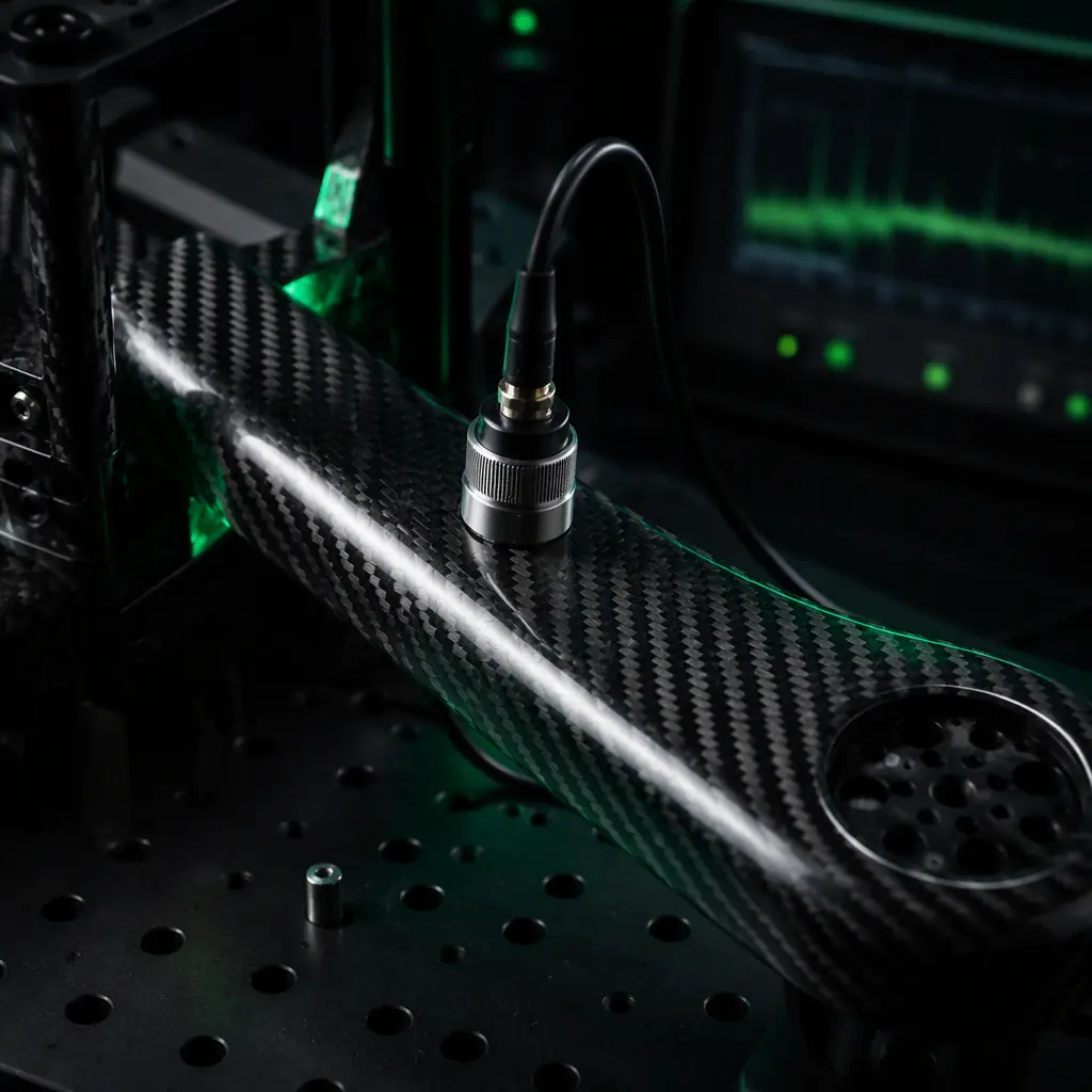
Ultrasonic, tap-test and X-ray methods that find voids and disbonds inside a tube or bonded joint.