
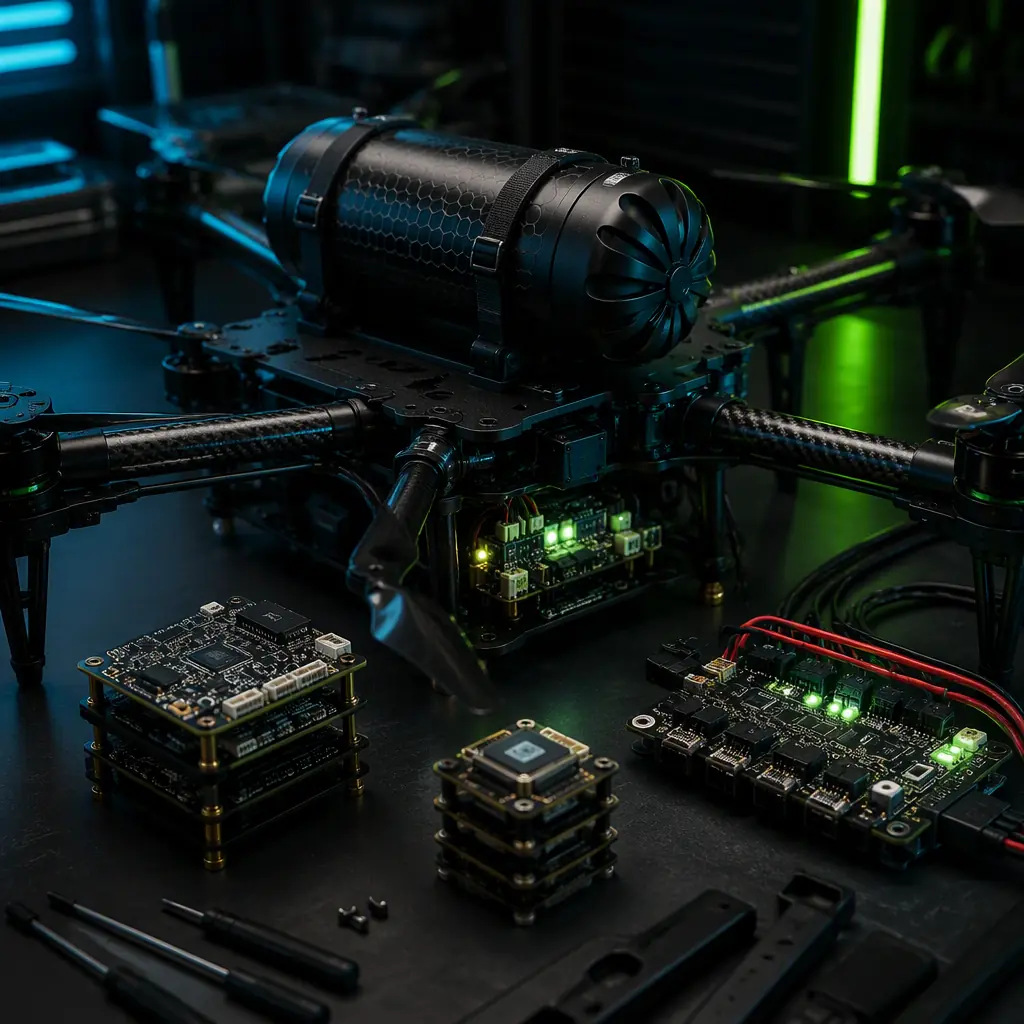
The safety case for an industrial UAV is built in layers, and each layer has a different failure coverage, mass cost and certification value. The regulatory baseline is shifting: ASTM F3322-22 (Standard Specification for Small Unmanned Aircraft System Parachutes) and EASA's Specific Operations Risk Assessment (SORA) methodology now treat the parachute, the redundant flight control system and the fail-safe behavior as measurable design attributes rather than optional accessories. For a 25 kg inspection or logistics platform, the complete safety package — a ballistic parachute, a dual flight controller, a redundant power bus and a motor-out mitigation strategy — adds 1.5–3.0 kg to the airframe (6–12% of the aircraft mass) and changes the procurement specification from a list of components to an engineered safety architecture. This guide walks through each layer with the numbers that matter for the RFQ: deployment times, descent rates, failure coverage percentages, certification evidence and acceptance test criteria.
The failure model: what actually kills an industrial UAV
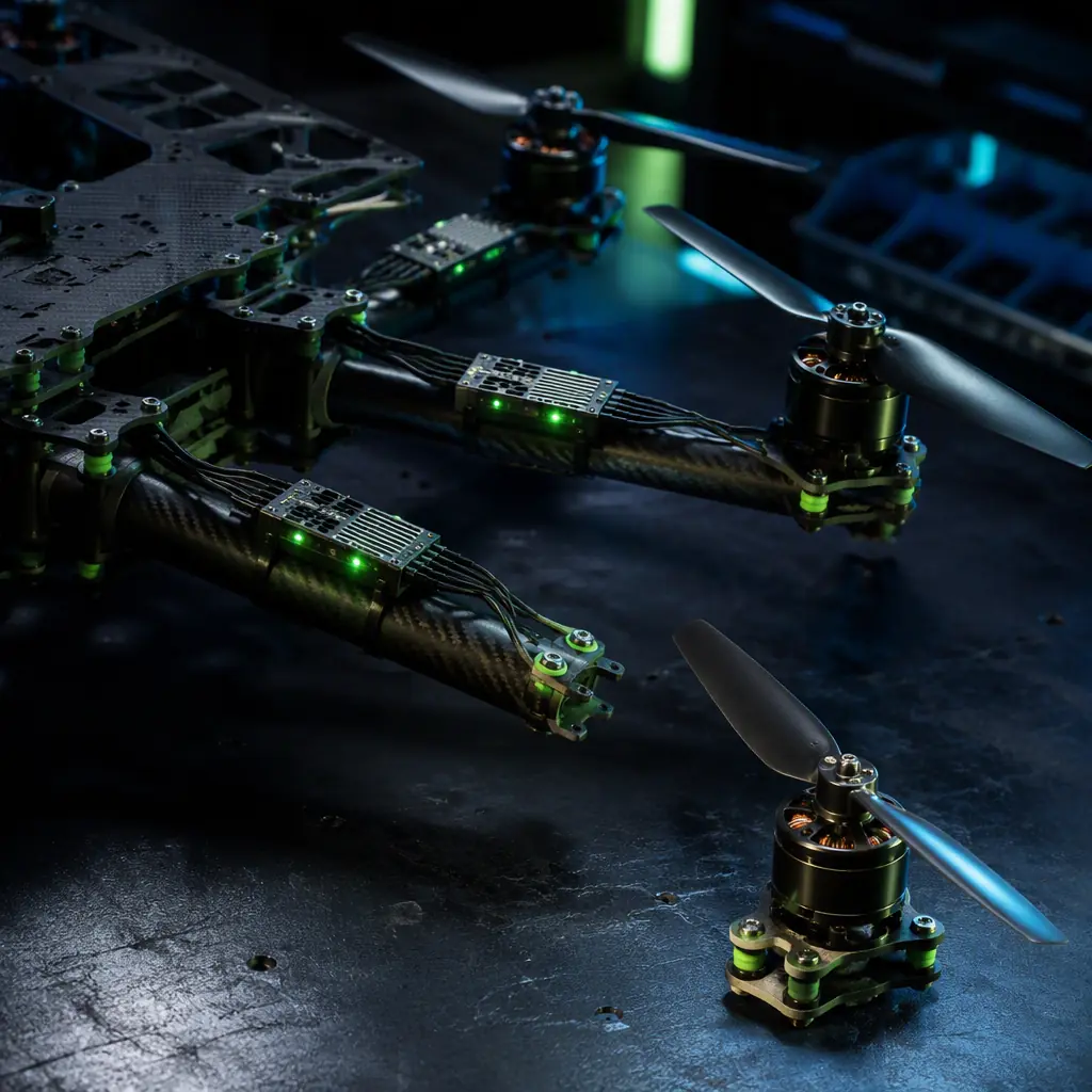
The safety architecture must be designed against the failure modes that dominate real-world industrial UAV accidents, not the theoretical ones. Field data from commercial UAV operators and the accident analysis published by the National Transportation Safety Board and European Aviation Safety Agency consistently rank the same five failure categories: propulsion system failures (motor, ESC or propeller — 35–45% of serious incidents), battery and power system failures (20–25%), flight controller or sensor failures (10–15%), communication link loss (10–15%) and structural or integration failures (5–10%). The percentages vary by platform class — a heavy-lift multirotor carrying a 10 kg payload is propulsion-dominated, while a fixed-wing mapping platform is more exposed to power and sensor failures — but the procurement implication is identical: the highest-value redundancy is propulsion redundancy, followed by power redundancy, then control redundancy.
The probability math explains why the parachute is not the first line of defense. A typical industrial multirotor with eight independent motor-ESC arms has a per-flight motor failure probability in the range of 1×10⁻⁴ to 1×10⁻³ per flight hour for well-maintained units — the probability that any one of the eight motors fails during a 1-hour flight is approximately 8×10⁻⁴ to 8×10⁻³, or roughly one motor failure per 125–1,250 flight hours across the fleet. With four motors, the per-flight probability doubles to approximately 1.6×10⁻³ to 1.6×10⁻². The parachute is the mitigation that catches the residual failures the redundancy cannot absorb — the simultaneous loss of two motors on the same side, the structural failure of an arm, or the complete loss of the flight controller. The redundancy layers reduce the frequency of the catastrophic event; the parachute bounds the consequence when it still occurs.
For the propulsion-side redundancy options — motor count, coaxial configurations, oversized ESC current ratings and motor-out flight modes — the UAV heavy-lift propulsion design guide covers the thrust-to-weight sizing and the redundancy architectures that determine whether a platform can survive a motor-out condition at all.
 Concept illustration
Ballistic recovery parachutes: sizing, deployment and certification evidence
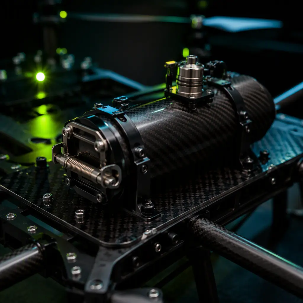
The ballistic recovery parachute (BRP) is the only safety component that can arrest a fully uncontrolled descent. The procurement specification for a UAV parachute system starts with the descent rate requirement: ASTM F3322-22 requires that the parachute system reduce the aircraft's rate of descent to a value that results in an impact velocity consistent with the aircraft's design crashworthiness — for a typical 25 kg industrial multirotor, a descent rate of 5.2–6.0 m/s at sea level. The canopy sizing follows the drag equation: D = ½ × ρ × v² × Cd × S, where D is the required drag force (equal to the aircraft weight, 25 kg × 9.81 m/s² = 245 N), ρ is the air density (1.225 kg/m³ at sea level), v is the target descent rate (5.5 m/s) and Cd is the canopy drag coefficient (0.75–0.85 for a well-designed cruciform or round canopy). Solving for the canopy area S = 2 × 245 / (1.225 × 5.5² × 0.8) = 490 / 29.6 = 16.5 m² — a canopy of roughly 4.1 m diameter for a 25 kg aircraft. The canopy mass scales with area at approximately 80–140 g/m² of canopy fabric, giving 1.3–2.3 kg of canopy fabric alone, plus the deployment system, the harness and the canister — which is why complete systems for the 20–30 kg class weigh 1.5–3.0 kg installed.
Deployment logic. The deployment decision is made by the parachute controller, not the pilot: the system continuously monitors the aircraft's attitude, vertical velocity and flight controller health, and deploys automatically when it detects an unrecoverable condition — a sustained inverted attitude, a vertical descent rate above the deployment threshold (typically 8–15 m/s, configurable), a motor-out condition with insufficient remaining thrust, or a total loss of the flight controller heartbeat. The deployment sequence is: the pyrotechnic or spring-driven actuator fires (10–50 ms), the pilot chute extracts the main canopy (0.3–0.8 s total to canopy inflation for a ballistic system, 1.5–3.0 s for a spring-deployed system at typical airspeeds), and the aircraft transitions from free fall to canopy-controlled descent. The minimum deployment altitude is a critical specification: for a 25 kg aircraft at a 5.5 m/s descent rate, the total time from the deployment command to a survivable impact — including the 0.5 s inflation time and the 30–50 m of altitude consumed during the inflation and the transient — requires a deployment altitude of 50–100 m AGL for a ballistic system, versus 150–300 m for a spring-deployed system. The procurement team must specify the minimum operating altitude for automatic deployment and verify it against the mission profile: a low-altitude inspection mission at 30 m AGL cannot rely on a parachute that needs 100 m to deploy.
Certification evidence. ASTM F3322-22 defines the test and documentation requirements for small UAS parachutes: a minimum of two successful live-drop tests at the maximum rated weight (the test aircraft dropped from a crane or a chase aircraft at the rated deployment conditions), a test at the minimum operating altitude, a test with the deployment triggered by each automatic deployment condition, and documentation of the descent rate, the deployment time and the landing impact energy. The certification evidence the procurement team must request: the test report with the drop test data (altitude, airspeed, aircraft weight, descent rate vs time, impact velocity), the canopy and hardware inspection criteria, the service life and repack interval (most systems require repacking every 6–12 months or after any deployment), and the environmental ratings (operating temperature range, rain and wind limits). For operations over people under EASA SORA or the FAA's operational approval process, the parachute system's test evidence is the primary mitigations argument for the "severe injury" risk — a system that demonstrates a 5.5 m/s descent rate and a 30 J impact energy at the maximum weight provides the quantitative basis for the risk reduction claim.
 Concept illustration
Redundant flight controllers: voting, cross-checking and the switchover transient
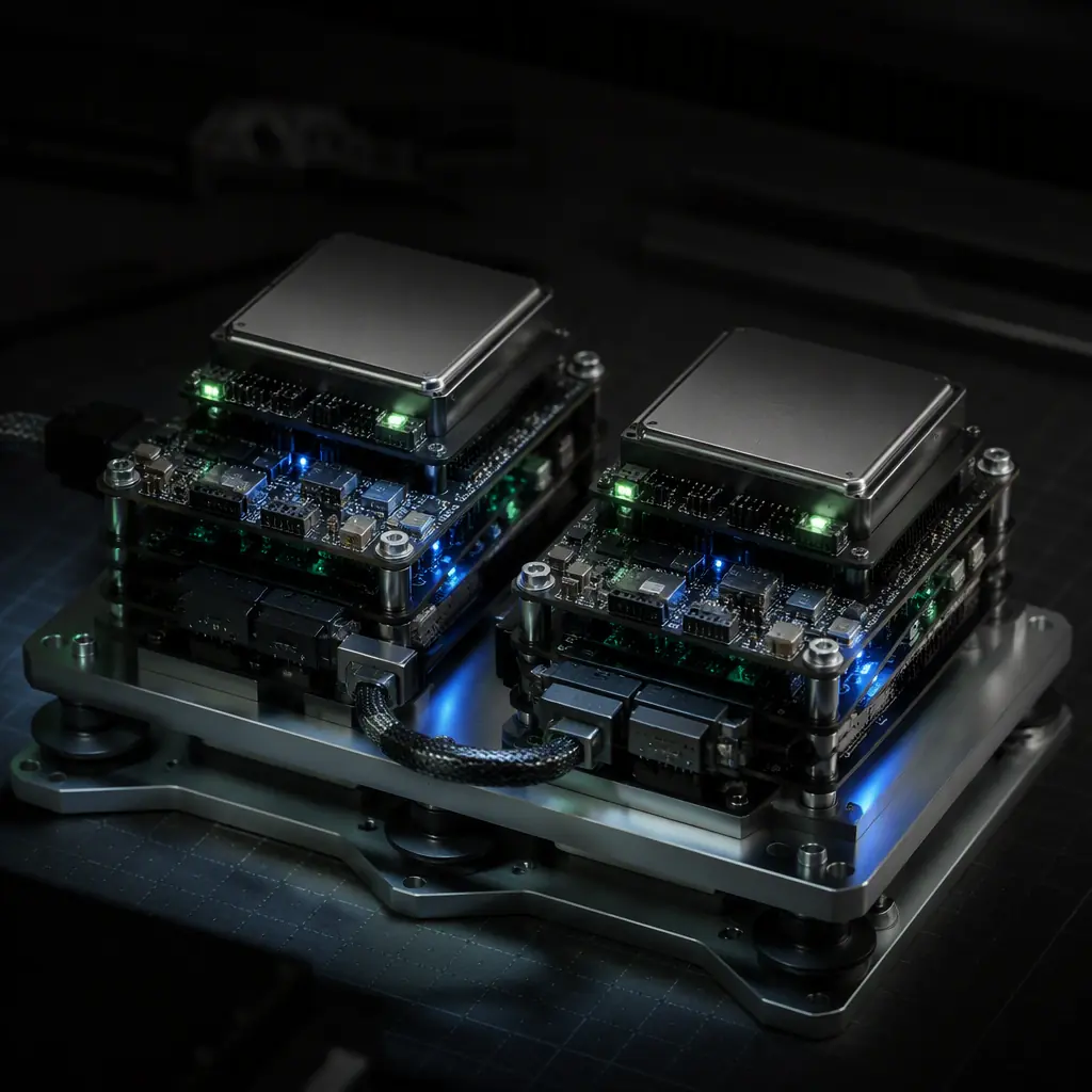
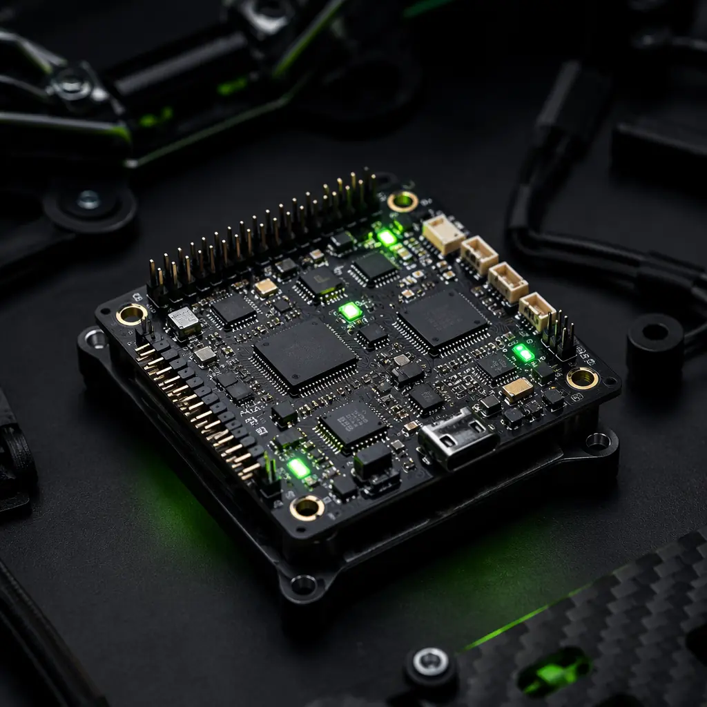
The flight controller is the single point of failure that the parachute cannot fully mitigate — if the autopilot locks up or produces erroneous output, the aircraft may enter an attitude from which recovery is impossible before the parachute controller can respond. The redundant flight control architecture addresses this with two (or three) flight controllers running the same control loop and comparing outputs. The procurement specification for a dual flight controller stack covers four design decisions: the voting strategy, the sensor cross-check, the switchover transient and the actuator interface.
Voting strategy. The two most common architectures are dual-active with cross-checking (both controllers compute the actuator commands, compare them every control loop cycle and switch to the healthy unit on disagreement) and active-standby (the primary controller flies the aircraft; the standby controller monitors the primary's health and takes over on a heartbeat loss or a commanded switch). For a dual-active system at a 1 kHz control loop, the cross-check must complete within one loop period — the controllers exchange their computed actuator outputs and a checksum over a high-speed serial link (CAN FD at 1–2 Mbit/s or UART at 921,600 baud) every 1 ms, and a disagreement beyond the tolerance (typically 5–10% of the commanded output for more than 3–5 consecutive loops) triggers the switch. The sensor cross-check extends the same logic to the inertial measurement units: each flight controller fuses its own IMU data, and the two controllers' attitude estimates must agree within the cross-check tolerance (typically 2–3° in pitch and roll) before the system trusts either estimate. The UAV sensor fusion and redundant navigation guide covers the IMU voting schemes — dual, triple and heterogeneous configurations — that the redundant flight controller depends on for its attitude reference.
Switchover transient. The critical parameter is the maximum time between the primary's failure and the standby's assumption of control, because the aircraft continues to fly (or fall) during the switchover. For a multirotor in hover, a 100 ms loss of active control is generally recoverable (the aircraft loses altitude and drifts, but the attitude remains stable); a 500 ms loss may induce a significant attitude excursion; a 1 s loss at high power is often unrecoverable. The specification should require a switchover time of ≤ 100 ms — which dictates that the standby controller must be fully powered, running the control loop and receiving the IMU data continuously (a "hot" standby), not powered down or in a low-power state. The switchover must also be transparent to the ESCs: if the two controllers share a CAN bus, the standby must be able to take over the bus ownership within the switchover window without a bus re-initialization.
Actuator interface. The dual controller architecture doubles the potential for actuator conflicts — both controllers must not drive the same ESC with different commands. The common solutions are a dedicated actuator arbitration board (a small PCB that selects the active controller's PWM or CAN output based on the health signal) or a redundant CAN bus with bus arbitration. The arbitration board adds 30–80 g and introduces its own failure mode, so the procurement team should require the supplier to document the arbitration board's failure behavior — the board must fail to the healthy controller's output, not to a disconnected state. For the ESC side of the actuator interface, the UAV communication protocols guide covers the CAN and DShot signaling that the arbitration and the redundant bus depend on.
 Concept illustration
Redundant power: dual batteries, isolated buses and the ideal-diode OR
Power redundancy is the layer that protects against the second-largest failure category — battery and power system failures — and it is the most cost-effective redundancy on the aircraft: a dual-battery architecture with an isolated power bus adds 200–600 g of switching and monitoring hardware while eliminating the single largest energy failure mode. The procurement specification for the redundant power system covers the battery architecture, the bus isolation and the power monitoring.
Battery architecture. The two standard configurations are parallel packs (two identical batteries connected in parallel through an OR-ing circuit, each sized to carry the full mission load) and independent banks (two batteries powering separate bus segments — the flight controller and the avionics on one bank, the propulsion ESCs split across both). The parallel configuration provides capacity redundancy (if one pack fails, the other carries the full load until the aircraft lands) but not isolation (a short in one pack can pull the shared bus down). The independent bank configuration provides both — but requires the aircraft's loads to be segregated, which complicates the wiring. The UAV battery and power management guide covers the LiPo and Li-Ion pack selection, the BMS architecture and the state-of-charge management that the redundant configuration depends on.
Bus isolation. The OR-ing circuit that joins the two packs must satisfy three requirements: no reverse current flow between the packs (a charged pack must not charge a failed pack), automatic switchover on pack failure within the control loop timeframe (≤ 10 ms for the avionics bus, where a brownout resets the flight controller) and fault containment (a shorted pack must be disconnected, not allowed to drag the bus). The practical implementations are ideal-diode OR-ing controllers (e.g., the LTC4370 or TPS2410 families, which replace the Schottky diode's 0.3–0.5 V drop with a MOSFET-based ideal diode that drops 20–50 mV at full load — critical for a 6S–14S propulsion bus where every 100 mV of bus sag reduces the motor's available voltage and thrust) and mechanical or solid-state contactors for the high-current propulsion path. The power distribution board design — copper weight, trace width and the connector selection — is covered in the UAV connectors, wiring and power distribution guide.
Power monitoring. Redundancy is only effective if the aircraft knows which path has failed: the specification should require per-pack voltage, current and temperature monitoring with the telemetry streamed to the ground control station, and the fail-safe logic should trigger a return-to-launch when the remaining capacity of the surviving pack falls below the energy required for the return flight plus a 20% reserve. For a 25 kg multirotor drawing 2.8–3.2 kW in hover with two 6S 22,000 mAh packs, the return-flight energy for a 2 km RTL is typically 150–250 Wh — the fail-safe threshold on the surviving pack should be set at that value plus 20%, which the BMS communicates to the flight controller as a "return now" signal rather than a "critical battery" warning.
Motor and ESC redundancy: thrust margin and the motor-out flight mode
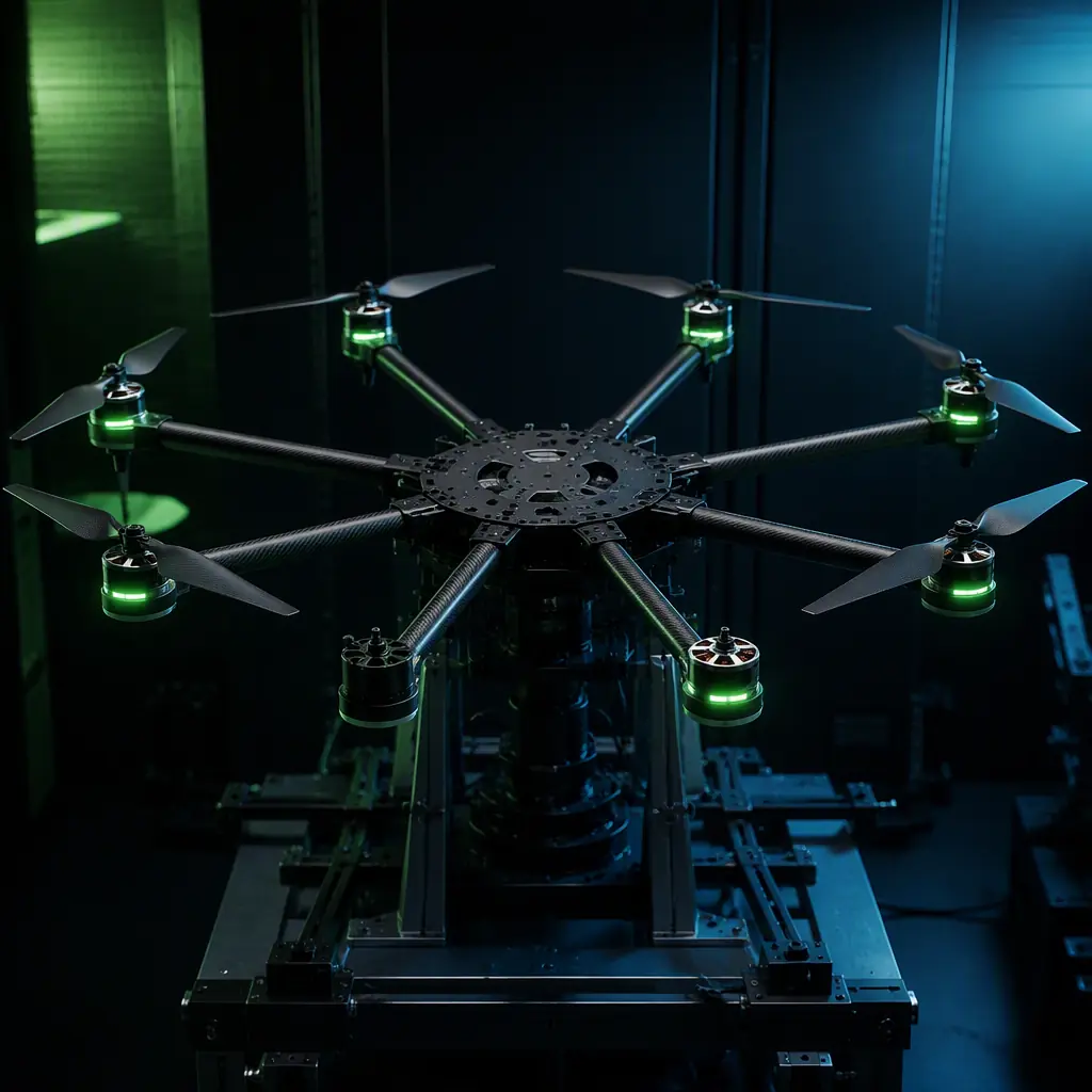
Propulsion redundancy is the highest-value layer because propulsion failures dominate the accident statistics — but it only works if the remaining motors have the thrust margin to maintain controlled flight. The governing parameter is the motor-out thrust-to-weight ratio: for an octocopter losing one motor, the remaining seven motors must produce at least the aircraft weight in thrust, and the control authority requires that the motors opposite the failed one can increase their output to counteract the yaw and roll moment from the asymmetric thrust. The rule of thumb for the procurement specification: the aircraft's maximum continuous thrust with one motor failed must be ≥ 1.2× the aircraft weight (for a hover-capable motor-out condition) or ≥ 1.5× (for a climb-capable condition). For an eight-motor aircraft, this translates to a per-motor thrust capability of approximately (1.2 × W) / 7 = 0.17 × W in the motor-out condition — versus 0.125 × W for the nominal hover — which means the motors must be sized at 35–40% above the nominal hover thrust, and the ESCs must be rated for the corresponding peak current. The UAV brushless motor KV selection guide and the UAV powertrain matching guide cover the thrust curve and the ESC sizing methodology that produces the motor-out margin.
The ESC side of the redundancy equation is thermal: in the motor-out condition, the surviving ESCs operate at elevated current for the duration of the degraded flight, and an ESC that cannot sustain the elevated current without thermal shutdown defeats the redundancy. The specification should require the ESC's continuous current rating at the motor-out condition to be ≤ 80% of the ESC's thermal limit (the current at which the ESC's junction temperature reaches the derated maximum), and the ESC should report its temperature over the telemetry bus so the flight controller can prioritize landing when the thermal margin is exhausted. For the ESC firmware's failure behavior — the individual ESC's response to a signal loss, a CAN bus fault or an over-current event — the ESC firmware selection guide covers the BLHeli_32, AM32 and FOC failure modes and the safety-relevant settings (e.g., DShot beacon and the motor-stop behavior on signal loss).
 Concept illustration
Fail-safe behavior: return-to-launch, geofencing and the lost-link protocol
The fail-safe behavior layer defines what the aircraft does when a failure occurs — and it is the layer where the procurement specification must be written as a behavioral contract, not a component list. The three critical fail-safe behaviors are the lost-link protocol, the return-to-launch (RTL) decision logic and the geofence response, and each must be defined with explicit trigger conditions, actions and termination criteria.
Lost-link protocol. The specification must define the radio link loss detection (typically a 2–5 s timeout with no valid telemetry or control frames, configurable per the link budget), the aircraft's behavior during the loss (hold position for a short window, then RTL) and the behavior on link re-acquisition (resume the mission or continue the RTL — the decision must be pre-programmed, not left to the operator). The lost-link behavior interacts with the remote identification and BVLOS requirements — the UAV Remote ID and BVLOS compliance guide covers the regulatory context, and the UAV RF communication systems guide covers the link budget and the redundancy architecture (dual radios, 4G/LTE fallback) that determine how often the lost-link condition actually occurs.
Return-to-launch decision logic. The RTL trigger conditions should be defined as a prioritized list: command from the operator, lost link beyond the hold window, battery energy below the return threshold, a propulsion fault (motor-out beyond the flight mode's capability), an avionics fault (IMU disagreement, GPS loss beyond the navigation tolerance) or a geofence breach. Each trigger must have a defined RTL trajectory (direct return at the cruise speed, climb to the return altitude, or a pre-planned corridor) and a defined termination (auto-land at the launch point, loiter for operator intervention, or proceed to the designated emergency landing zone). The RTL energy reserve calculation — the battery energy required for the return path plus the 20% reserve — is the link between the power monitoring layer and the fail-safe layer.
Geofence response. The geofence defines the operational volume — the lateral and vertical boundaries the aircraft must not exceed — and the response on breach: an immediate return toward the center of the volume, an automatic RTL, or a controlled descent. The specification should require the geofence to be active in the flight controller at all times (not dependent on the ground station link), with the boundary stored in the flight controller's non-volatile memory and a breach response time of ≤ 500 ms. For the autopilot platforms that implement these fail-safe behaviors — ArduPilot and PX4 both provide configurable lost-link, RTL, geofence and battery fail-safe parameters — the ArduPilot vs PX4 comparison covers the fail-safe configuration differences and the safety architecture of each platform.
 Concept illustration
Procurement checklist: specifying the safety and redundancy package
The following eight-line-item specification translates the safety architecture into an RFQ-ready checklist. Each line item includes the verification method the procurement team should use to confirm the requirement before acceptance.
1. Ballistic recovery parachute. The parachute system shall reduce the aircraft's descent rate to ≤ 6.0 m/s at the maximum take-off weight, deploy automatically within 0.8 seconds of the deployment command at altitudes ≥ 50 m AGL, and be certified to ASTM F3322-22 with live-drop test evidence. Verification: the supplier's test report showing the descent rate vs time plot at the maximum weight, the deployment time, the minimum deployment altitude and the impact energy.
2. Parachute repack and service life. The parachute system shall have a documented repack interval of ≤ 12 months, a service life of ≥ 5 years, and an inspection procedure that does not require factory return for routine checks. Verification: the maintenance manual with the repack procedure, the inspection checklist and the spare parts list (canopy, harness, actuator, canister).
3. Redundant flight controller. The aircraft shall be controlled by two independent flight controllers with a switchover time of ≤ 100 ms, an attitude cross-check tolerance of ≤ 3°, and a sensor cross-check covering the IMUs, the barometer and the GNSS receivers. Verification: the supplier's switchover test report documenting the time from the primary's failure injection to the standby's assumption of control, and the cross-check tolerance test data.
4. Redundant power bus. The aircraft shall have two independent power sources with an OR-ing circuit that isolates a failed pack within ≤ 10 ms, per-pack voltage, current and temperature telemetry, and a fail-safe return threshold set at the return energy plus 20% reserve. Verification: the power distribution test report with the switchover waveform, the reverse-current test data and the telemetry log from a full mission flight.
5. Motor-out capability. The aircraft shall maintain controlled flight with one motor failed, with a motor-out thrust-to-weight ratio of ≥ 1.2× and the surviving ESCs rated to sustain the motor-out current without thermal shutdown for ≥ 5 minutes. Verification: the flight test report with a documented in-flight motor failure injection (or a ground test with the propeller removed), the motor-out flight video and the ESC temperature log.
6. Fail-safe behavior. The flight controller shall implement the lost-link protocol (hold then RTL), the RTL decision logic with the prioritized triggers, the geofence with a ≤ 500 ms breach response and the battery fail-safe, with all parameters configurable and stored in non-volatile memory. Verification: the supplier's fail-safe configuration table, the simulator test report for each trigger condition and the flight test evidence for the lost-link RTL.
7. Safety documentation. The safety package shall be documented in a safety case report covering the failure modes, the risk mitigations and the residual risk, consistent with the EASA SORA or the applicable national operational risk assessment framework. Verification: the safety case report with the failure tree, the mitigation mapping and the residual risk assessment.
8. Production quality. The safety components shall be produced under a quality system with lot traceability, 100% functional testing of the parachute actuators and the power switching hardware, and the first-article inspection for each production lot. Verification: the supplier's ISO 9001 certificate, the lot traceability records and the first-article inspection reports. The UAV supplier evaluation checklist covers the full audit methodology for qualifying the safety component supplier.
For the certification documentation that accompanies the safety package — the CE Declaration of Conformity, the FCC equipment authorization, the NDAA Section 848 compliance statement and the quality system certification — the UAV certification and compliance guide covers the regulatory framework that applies to all UAV subsystems, including the parachute and redundancy-specific evidence covered in this article.
Explore custom engineering Back to Blog
Continue Reading
UAV Sensor Fusion and Redundant Navigation
The dual and triple IMU voting schemes, dual GNSS with RTK and the EKF architecture that the redundant flight controller depends on for its attitude and position reference.

UAV Battery and Power Management
The LiPo and Li-Ion pack sizing, BMS architecture and state-of-charge management that the redundant dual-battery power bus depends on.
UAV Heavy-Lift Propulsion Design
The motor, ESC and propeller sizing for sustained hover and the motor-out thrust margin that makes propulsion redundancy effective.

UAV Certification & Compliance Guide
The CE, FCC, NDAA and aviation authority certification framework that the parachute and redundancy test evidence must fit into.
ArduPilot vs PX4 Autopilot
The fail-safe configuration, geofence and RTL behavior differences between the two open-source autopilot platforms that implement the safety layer.