
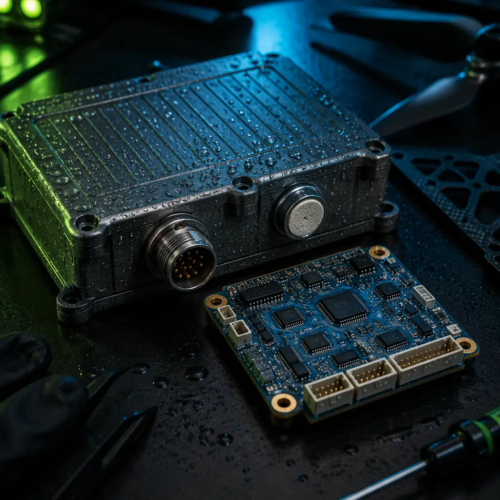
The waterproofing specification for a UAV starts with a fundamental distinction: splash resistance, rain operation and immersion are different engineering problems with different IP ratings, different test methods and different costs. An IP54 rating (dust-protected, water splashed from any direction) is achievable with a sealed enclosure and a gasketed hatch; an IP65 rating (jet water) requires the same enclosure with the fasteners torqued to spec and every cable entry glanded; an IP67 rating (temporary immersion to 1 m for 30 minutes) requires the enclosure to survive the pressure differential of a 1 m water column, which in turn requires a pressure-equalizing vent or a fully potted interior. The procurement team must map the mission environment to the required rating before selecting components — a mapping and survey platform that lands in wet grass needs a different specification than an agriculture sprayer that flies through chemical mist, and both differ from a maritime inspection platform that may be recovered from salt water.
Decoding IP ratings: what the digits actually mean for UAV components
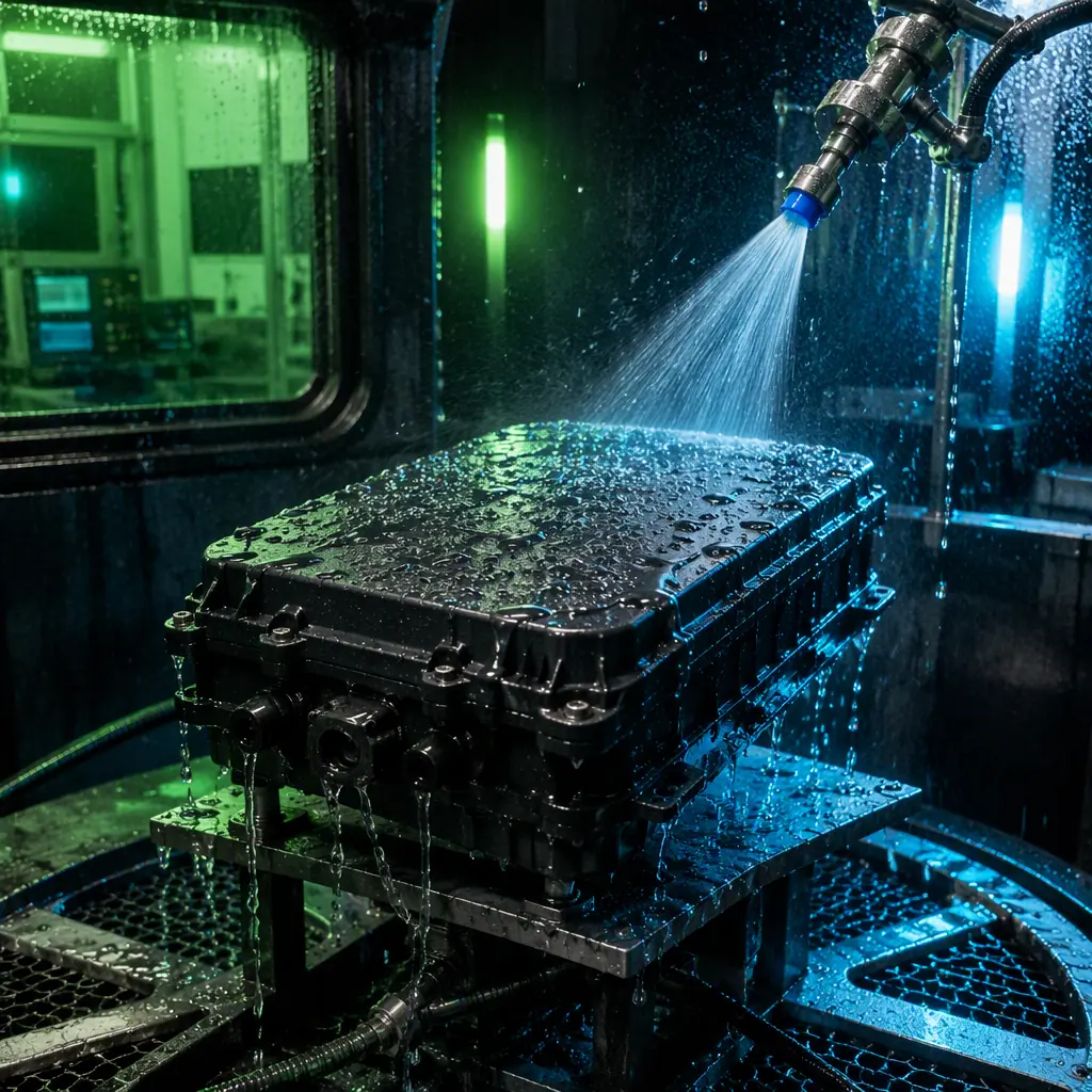
The IP (Ingress Protection) code defined in IEC 60529 is a two-digit classification: the first digit rates protection against solid particles (dust, sand, tools), the second digit rates protection against water. For UAV components, the first digit is almost always 5 (dust-protected — dust does not enter in sufficient quantity to interfere with operation) or 6 (dust-tight — no dust ingress at all), and the practical question is the second digit. The water ratings that matter for UAV procurement: IPX4 (splashing water from any direction — a light rain or the spray from rotors in wet grass), IPX5 (water jets from any direction — a hose or heavy rain), IPX6 (powerful water jets — deck washing or a marine environment), IPX7 (temporary immersion at 1 m depth for 30 minutes — a crash into a puddle or a wave wash) and IPX8 (continuous immersion at a specified depth — the rating used for maritime and submersible platforms).
The test methods define the acceptance: IPX4 is tested with a 10-minute oscillating spray at 10 L/min, IPX5 with a 6.3 mm nozzle at 12.5 L/min from 3 m, IPX6 with a 12.5 mm nozzle at 100 L/min, and IPX7 with immersion at 1 m for 30 minutes with the device powered off (the IEC test does not require operation during immersion — a distinction that matters when a supplier claims "IP67" for a component that is only certified in the off state). The procurement team should request the test report that matches the mission: a supplier's IP65 test report (jet water) does not prove splash resistance in the sense the operator needs, and an IP67 certification tested powered-off does not guarantee the component survives immersion while the motors are running. The UAV certification and compliance guide covers how the IP rating evidence fits into the overall CE, FCC and aviation authority documentation package.
A common procurement mistake is specifying "waterproof" without a rating and accepting an IP54 part where the mission needs IP65. The cost difference is usually small at the component level — an IP65-rated connector costs 20–40% more than the unrated equivalent — but the failure cost is the aircraft. The specification should state the required rating explicitly for each subsystem: the flight controller enclosure (IP65 minimum for rain operation), the ESC and power distribution compartment (IP65), the battery bay (IP54 — the battery needs airflow for cooling, so the bay is ventilated and splash-shielded rather than sealed), the payload and camera (IP65), and the antenna and vent penetrations (rated for the enclosure they pass through).
 Concept illustration
Conformal coating: the PCB-level waterproofing that no enclosure can replace
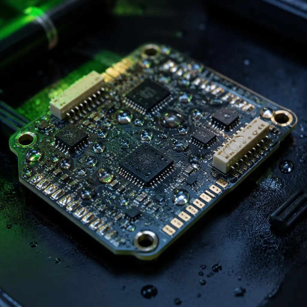
Conformal coating is a thin insulating polymer film applied to the PCB after assembly that protects the circuitry from moisture, condensation, chemical attack and conductive contamination. It is the second line of defense behind the enclosure — the layer that keeps the flight controller alive when the enclosure seal leaks, the vent condenses or the crash opens a seam. The procurement specification for conformal coating covers the chemistry, the thickness, the coverage and the inspection evidence.
Chemistries. The four coating families used in UAV avionics, each with a different trade-off: acrylic (the AR type per IPC-CC-830) is the most common — easy to apply, easy to rework with solvent, good moisture resistance but limited chemical resistance and a low maximum operating temperature (~125°C); silicone (SR) offers the widest operating temperature range (−65°C to +200°C), the best protection against vibration-induced stress cracking and good moisture resistance, but it is difficult to rework and its soft surface attracts dust; polyurethane (UR) provides excellent chemical and abrasion resistance with a hard finish but is difficult to rework; and parylene (XY) is applied by vacuum deposition as a truly conformal film that follows every component contour — the best protection for high-reliability avionics but the most expensive process (typically 3–5× the cost of acrylic per board) and effectively impossible to rework. For a flight controller exposed to condensation and agricultural chemicals, the recommended specification is a 25–75 µm acrylic or silicone coating over the whole board with the test pads, the connectors and the barometer port masked.
Thickness and coverage. IPC-CC-830 specifies the coating thickness by type: 25–75 µm for acrylic and polyurethane, 50–100 µm for silicone, and 0.5–50 µm for parylene. The coverage is where field failures originate: the coating must cover the solder joints, the component leads and the board edges (the capillary path that draws moisture under the coating), and the masking must protect the connector contacts, the barometer and pitot ports, the test points and the battery terminals. The procurement team should require the supplier's coating process specification — the application method (spray, dip or selective coating robot), the masking layout, the cure schedule and the inspection criteria (visual per IPC-A-610, with the coating thickness verified by a calibrated thickness gauge on a process coupon, not a spot check on the production board).
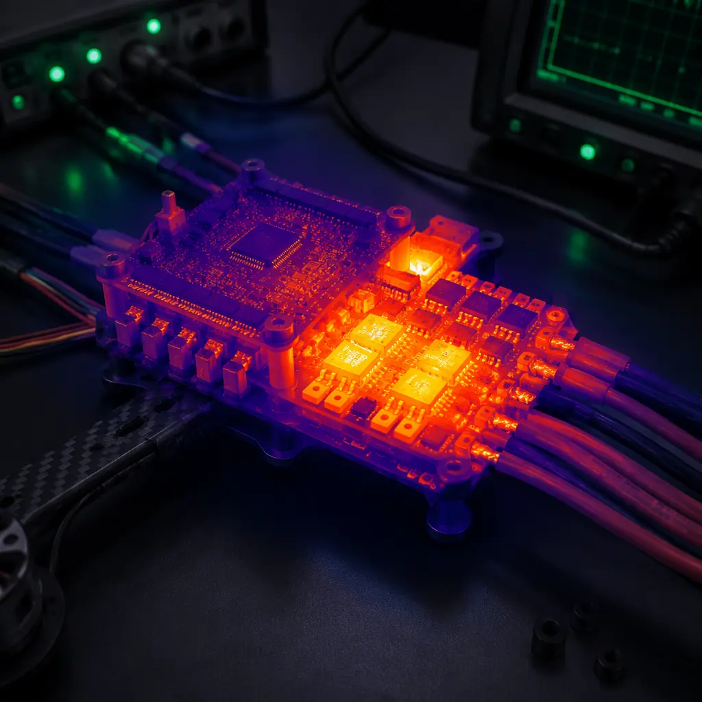
Rework and the coating-thermal interaction. The coating decision interacts with the thermal management of the UAV electronics: a thick silicone coating over a high-power ESC acts as an insulating blanket, raising the component junction temperature by 5–15°C compared with an uncoated board. The UAV thermal management guide covers the heat sink and thermal interface design that must account for the coating's thermal resistance — the typical approach is to leave the high-power MOSFETs and their heat sinks uncoated (masked) and rely on the enclosure and the potting for their protection. For the rework requirement, the specification should state that the coating on the flight controller must be removable (acrylic and polyurethane are solvent-strippable; silicone requires mechanical or plasma removal) so the board remains repairable across its service life.
 Concept illustration
Sealed connectors, cable glands and the wiring harness
The wiring harness is the most common water ingress path in a sealed UAV: every cable that enters the enclosure is a potential leak, and the connector itself is often the weakest seal. The procurement specification for the harness covers the connector rating, the cable entry and the internal routing.
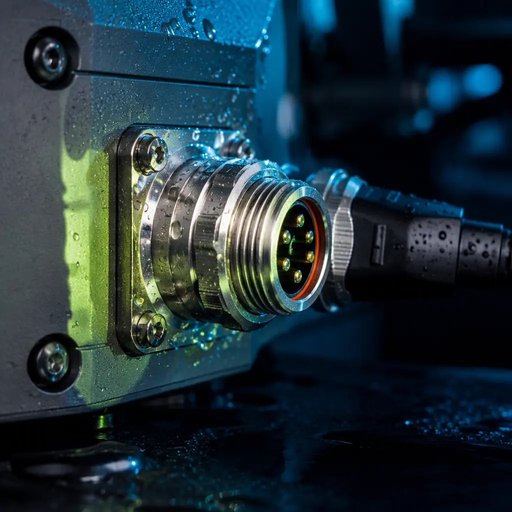
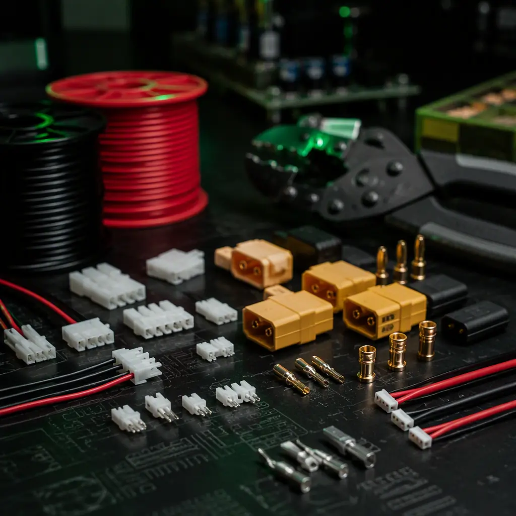
Connector ratings. For the enclosure penetrations, the specification should require IP67-rated circular connectors (the M12 and M16 families with threaded couplings, or the aviation-grade circular connectors used in the industrial sensor market) for the power and the data interfaces, with the mating halves specified as a matched pair (an IP67 plug mated to an unrated receptacle does not achieve IP67). The locking mechanism matters under vibration: a threaded or bayonet coupling holds the seal under the vibration spectrum of a multirotor, while a friction-locked connector can work loose and break the seal in flight. The UAV connectors, wiring and power distribution guide covers the JST, Molex and Anderson Powerpole families used for the internal harness — the internal connectors do not need IP ratings (they live inside the sealed enclosure) but the wire gauge, the insulation and the strain relief selection applies equally.
Cable glands. Where a cable passes through the enclosure wall without a bulkhead connector, the cable gland (cord grip) must be rated for the enclosure's IP level: a nylon PG7–PG16 gland with a neoprene or TPE seal provides IP68-rated cable entry when the gland is torqued to spec and the cable diameter matches the gland's sealing range. The two failure modes to specify against: over-tightening (which crushes the cable and damages the conductors) and under-tightening (which leaves a gap). The specification should require a torque value for each gland size and a harness layout that keeps the cable bending radius above the manufacturer's minimum inside the gland.
Internal routing and the drip path. The harness design inside the enclosure should route water away from the electronics even when the enclosure is breached: the connectors should be oriented with the contacts facing down, the cables should drip away from the boards before they reach the components, and the lowest point of the enclosure should include a drainage path (a small weep hole with a one-way valve, or a vent that doubles as a drain) for the water that enters during a crash recovery. For the agriculture and environmental platforms that operate in spray and rain, the precision agriculture UAV components guide and the environmental monitoring components guide cover the chemical-resistant and all-weather hardware requirements specific to those missions.
 Concept illustration
Pressure-equalizing vents: stopping condensation in the sealed compartment
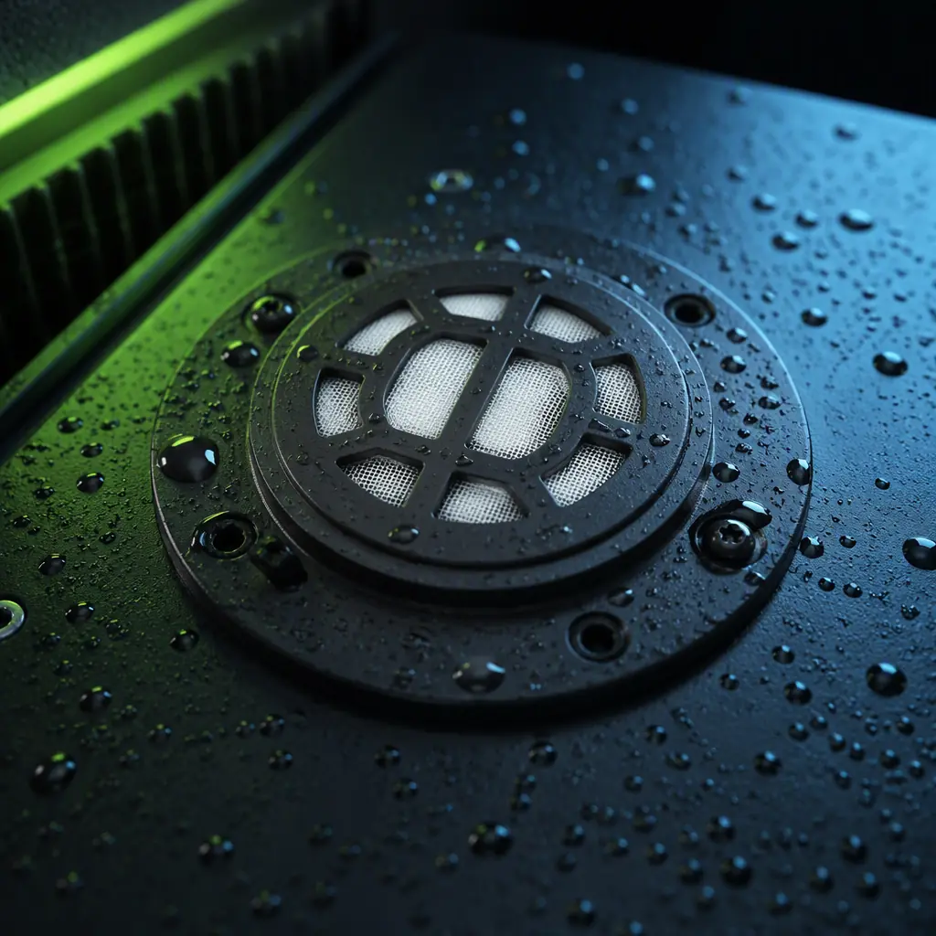
The paradox of the sealed enclosure: a perfectly sealed UAV compartment that is opened on the ground, flown to altitude and landed in cooler air draws moisture into the sealed volume as the internal pressure and temperature change — the classic "breathing" effect that produces condensation on the flight controller even though the enclosure never leaked. The pressure-equalizing vent (a membrane vent such as the Gore or equivalent ePTFE product line) solves this by allowing air to pass through while blocking liquid water and particles. The procurement specification for the vent covers the airflow rate, the water entry pressure and the mounting.
Airflow and water entry pressure. The vent's airflow rating (typically expressed in ml/min/cm² at a 70 mbar pressure differential, or the time to equalize a defined enclosure volume) must be matched to the enclosure volume and the altitude change rate of the mission: a 5 L enclosure climbing at 5 m/s experiences a pressure differential that the vent must equalize fast enough to avoid stressing the enclosure seals — a typical specification is a vent with a ≥ 500 ml/min/cm² airflow at 70 mbar for a 5 L enclosure. The water entry pressure (the pressure at which water is forced through the membrane) must exceed the enclosure's immersion rating: for an IP67 enclosure (1 m immersion = approximately 10 kPa of hydrostatic pressure), the vent's water entry pressure should be ≥ 15 kPa to provide margin. The membrane's performance degrades with contamination — salt, dust and chemical spray clog the ePTFE pores — so the vent should be mounted in a protected location (under the fuselage, behind a lip) and the specification should include the replacement interval.
Condensation management. Even with a vent, rapid temperature changes can produce condensation inside the enclosure. The mitigation options: a conformal-coated board (the coating protects the circuitry from the condensation), a desiccant pack (limited capacity — a 10 g silica gel pack absorbs approximately 3 g of water, useful for storage but not for repeated flight cycles), and a heater or a sealed compartment with a nitrogen purge for the high-value avionics. For the inspection and maritime platforms that operate in high-humidity environments, the UAV industrial inspection components guide and the UAV public safety components guide cover the all-condition operation requirements that drive the condensation specification.
Potting, sealing and the motor and payload protection
For the components that cannot be enclosed — the ESCs mounted in the propulsion arms, the sensor modules on the gimbal, the antennas — the waterproofing options are potting (encapsulating the assembly in a resin block), conformal coating plus a splash shield, or a rated housing. The procurement specification for each category:
Potting. Potting compounds (two-part polyurethane or epoxy resins) fully encapsulate the electronics, providing the highest level of environmental protection — a potted ESC is effectively immune to water, vibration and chemical attack. The trade-offs: the potting traps heat (a potted ESC's junction temperature rises 10–25°C compared with a free-air board at the same current — the thermal derating must be included in the ESC selection), the assembly is unrepairable, and the weight adds 20–60 g per potted module. The specification should require the potting to cover the board to the specified height, the connector pins and the wire exits to be masked or sealed, and the thermal performance to be verified by a bench test at the motor-out current. The motor and ESC thermal envelope is covered in the UAV thermal management guide, and the ESC current ratings in the ESC firmware selection guide.
Motors. Brushless motors are inherently exposed — the stator and the windings are open to the environment. The waterproofing measures: sealed bearings (2RS shielded bearings exclude dust and splash), a conformal or epoxy coating on the stator windings (applied before the stator is pressed into the housing), a sealed wire exit at the motor base, and drainage holes in the housing bell to let water out when the motor is recovered from immersion. The specification should require the motor's continuous current rating to be derated for the coating (the coating adds a thermal resistance between the windings and the housing) and the supplier's moisture test evidence — a documented motor running test in a water spray for the mission duration. The motor selection and KV matching context is covered in the UAV brushless motor KV selection guide.
Payload and camera. The payload compartment has its own waterproofing requirement — the gimbal and the camera are the most exposed components on the aircraft. The specification should require an IP65-rated payload housing, a hydrophobic-coated lens (a nano-coating that makes water bead and run off the optic), and a sealed gimbal with the slip-ring or flex-cable entry glanded. For the payload integration decisions — the sensor mounting, the cabling and the environmental protection — the UAV payload integration guide covers the full integration specification.
 Concept illustration
Procurement checklist: specifying waterproof and IP-rated UAV components
The following eight-line-item specification translates the waterproofing architecture into an RFQ-ready checklist. Each line item includes the verification method the procurement team should use before acceptance.
1. IP rating per subsystem. The flight controller enclosure, the ESC and power distribution compartment, the payload housing and the battery bay shall be rated IP65, IP65, IP65 and IP54 respectively (or the ratings specified for the mission environment). Verification: the supplier's IEC 60529 test reports for each enclosure, stating the test method (spray or immersion), the test duration and the acceptance criteria.
2. Conformal coating. The flight controller, the power distribution board and the ESC boards shall be conformal-coated with an acrylic or silicone coating at 25–75 µm (acrylic) or 50–100 µm (silicone) per IPC-CC-830, with the connectors, the barometer port, the test pads and the high-power components masked. Verification: the coating process specification, the thickness measurement records from the process coupons and the IPC-A-610 visual inspection evidence.
3. Sealed connectors. All enclosure penetrations shall use IP67-rated circular connectors with threaded or bayonet couplings, specified as matched plug-receptacle pairs. Verification: the connector datasheets with the IP67 rating and the test report, and the harness assembly records.
4. Cable glands. All cable entries without bulkhead connectors shall use glands rated IP68 with a specified torque value, and the cable diameter shall match the gland's sealing range. Verification: the gland datasheet and the assembly records with the torque values.
5. Pressure-equalizing vent. The sealed enclosures shall include a pressure-equalizing vent with an airflow rating matched to the enclosure volume and the mission altitude change rate, and a water entry pressure ≥ 15 kPa for IP67-rated enclosures. Verification: the vent datasheet and the supplier's membrane performance data.
6. Potting. The propulsion-arm ESCs (where exposed) shall be potted with the thermal derating documented, and the potted assembly shall be verified by a bench test at the motor-out current for ≥ 5 minutes without thermal shutdown. Verification: the potting process specification, the thermal test report and the weight records.
7. Motor protection. The motors shall use sealed bearings, coated windings, a sealed wire exit and drainage holes, with the continuous current rating derated for the coating. Verification: the motor datasheet with the derated current and the supplier's moisture test report.
8. Environmental test evidence. The complete aircraft shall pass a mission-profile environmental test — a 30-minute rain test at the rated IP level with the avionics powered, followed by a full functional check. Verification: the environmental test report with the test setup, the weather conditions and the post-test functional test results. The UAV supplier evaluation checklist covers the supplier audit methodology for verifying the test evidence and the production quality system.
For the component-level testing and validation practices that verify the waterproofing claims — the environmental test methods, the acceptance criteria and the first-article inspection requirements — the UAV propulsion testing and validation guide covers the test bench and the acceptance test framework that applies to the waterproofed propulsion and power components.
Explore custom engineering Back to Blog
Continue Reading
UAV Connectors, Wiring & Power Distribution
The JST, Molex and Anderson Powerpole families, wire gauge selection and the power distribution board design that the sealed harness connects together.
Precision Agriculture UAV Components
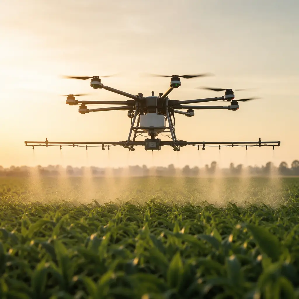
The chemical-resistant and corrosion-protected hardware requirements for platforms that fly through spray and mist — the most demanding waterproofing environment.
UAV Public Safety Components
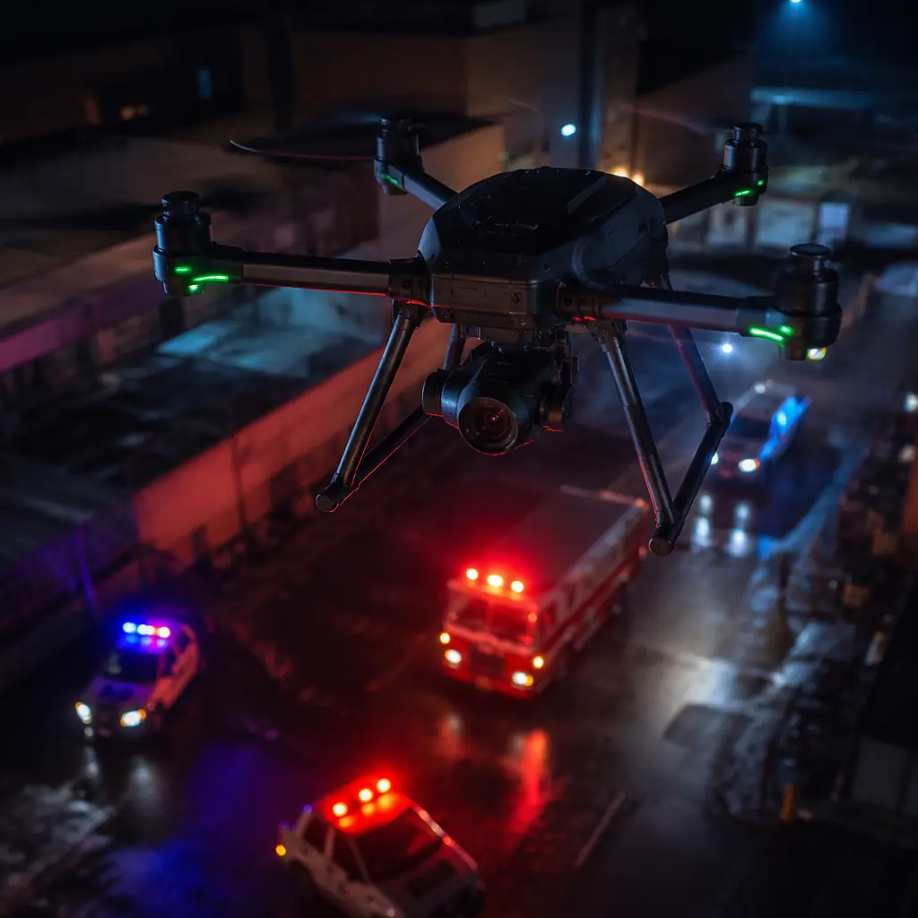
The weather resistance and all-condition operation requirements for first responder platforms that fly in rain, wind and marine environments.
UAV Thermal Management for Electronics
The heat sink sizing and the thermal interface design that must account for the insulating effect of conformal coating and potting on UAV power electronics.
UAV Environmental Monitoring Components
The long-endurance and remote-telemetry platforms that operate in rain, humidity and marine environments — the mission profile that drives the waterproofing specification.