
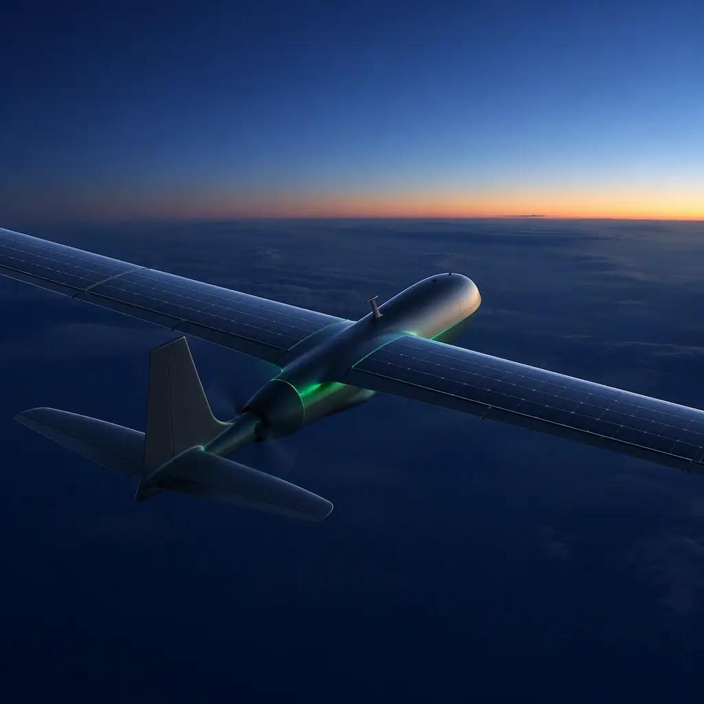
Endurance is not a battery spec; it is a systems-engineering result. The battery and power management guide covers the lithium side of the equation, chemistry, cycle life, charge management, and the hydrogen fuel cell guide covers the fuel-cell alternative. This guide sits between them: the architectures that combine solar harvesting and generator power with a battery bus, the component choices that make them work, and the missions where the added weight and complexity pay back in flight hours. It is written for the procurement and integration teams who are evaluating an extended-endurance platform rather than designing one from scratch.
Why endurance is the binding constraint in long-range operations
Battery energy density sets a hard ceiling on endurance for electric aircraft, and the ceiling is low. A 6S LiPo pack at 180 Wh/kg delivers about 950 Wh per kilogram; a typical industrial multirotor burns 150–400 W in cruise, so a kilogram of battery buys roughly 2.5–6 hours of flight in the best case. Before the reserve margin, the payload power draw and the thermal derating are subtracted. The payload power budgeting guide shows how the payload's draw (gimbal, compute, sensors, datalink) consumes the same bus that propels the aircraft, which is why real-world endurance is usually 40–70% of the battery-only theoretical number.
The missions that need more than that share a profile: linear assets to patrol (pipelines, borders, power lines), large areas to map in a single sortie, and remote or offshore locations where the logistics of battery swaps are the real cost. For those missions the procurement question is not "which battery" but "which energy architecture". And the answer is a trade between three: solar augmentation, a hybrid generator, or a fuel cell. The rest of this guide gives each its numbers.
Solar augmentation: what photovoltaic cells actually add to a fixed wing
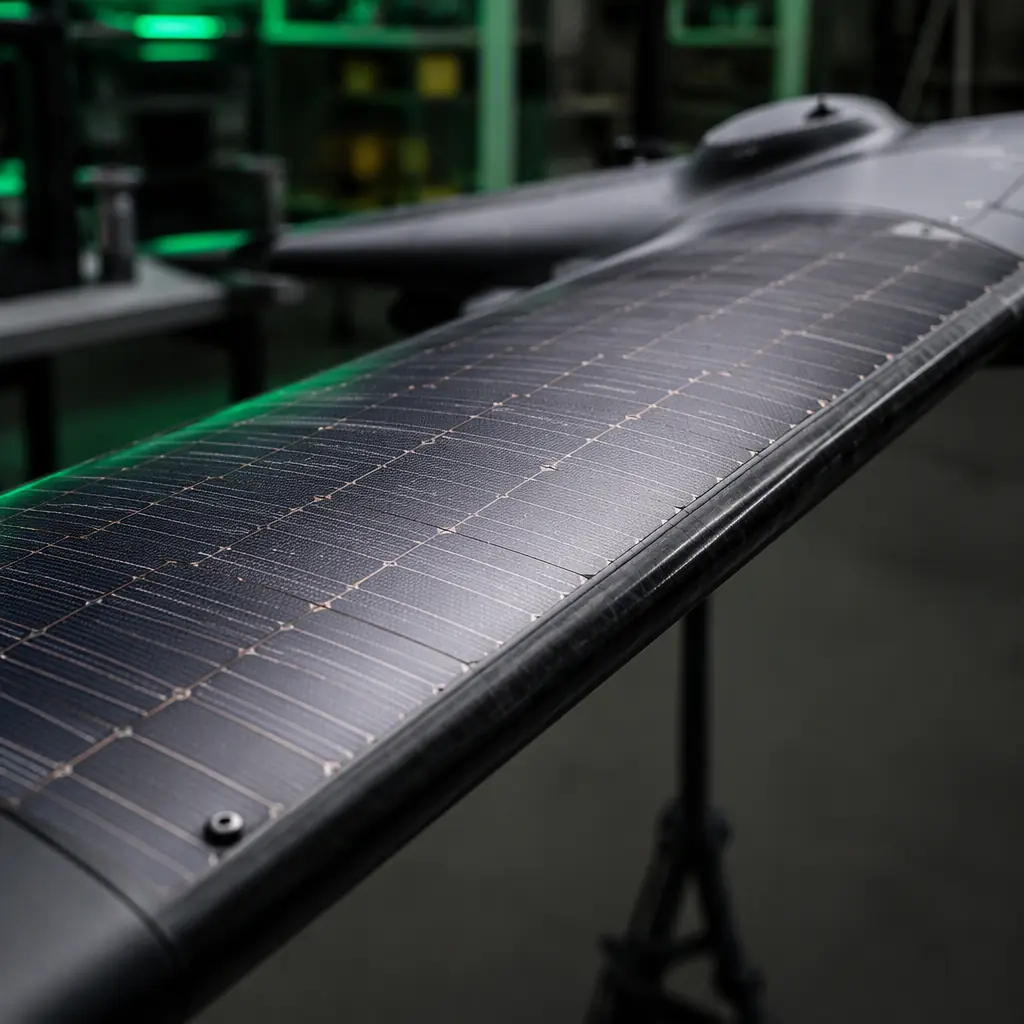
Photovoltaic cells do not replace the battery; they reduce the rate at which it drains. The physics: a modern flexible CIGS or silicon-perovskite cell delivers 20–25% conversion efficiency, which means roughly 200–300 W/m² of wing surface at high noon on a clear day, 100–150 W/m² in typical daytime conditions, and effectively zero at night or under heavy cloud. A fixed-wing UAV with 1.5 m² of usable wing area is therefore harvesting on the order of 150–450 W at midday, enough to offset a large fraction of cruise power, but not to fly on solar alone except in the special stratospheric class of aircraft.
The realistic procurement number for a daytime survey or patrol platform is an endurance extension of 15–30%, which matches the solar-augmentation figure the environmental monitoring guide cites for long-endurance remote deployments. The gain compounds with mission timing: a platform that launches at sunrise, loiters through the day and lands at dusk effectively doubles its sortie value compared to a battery-only platform of the same takeoff mass, because the harvested energy is continuously replacing what the aircraft burns. The price is paid in three places: the cells add 0.5–1 kg/m², the panel surface adds drag, and the MPPT electronics (covered below) add failure modes, the environmental monitoring guide makes the point that solar augmentation is a coupled trade with thrust and battery size, not a free add-on.
 Concept illustration
Hybrid-electric: the series generator that turns fuel into range
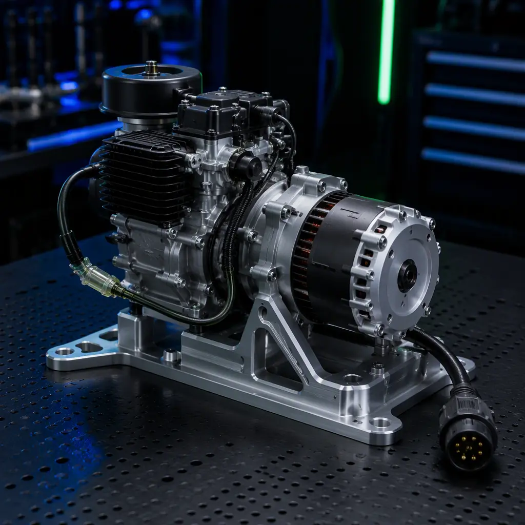
The hybrid-electric architecture that dominates extended-endurance UAVs is the series hybrid: an internal-combustion generator (engine plus alternator) produces DC power that feeds the same battery bus the motors draw from, so the aircraft always flies electric and the engine simply recharges the battery. The configuration is attractive because the electric propulsion chain, motor, ESC, flight controller, is unchanged from a pure-electric platform, and the generator can run at its optimal RPM regardless of airspeed.
The numbers that make the architecture work are the fuel's. Liquid fuel carries roughly 12,000 Wh/kg of chemical energy; even at a conservative 20–25% overall conversion efficiency (engine thermal efficiency, alternator losses, rectifier losses), a kilogram of fuel delivers 2,400–3,000 Wh to the bus, an order of magnitude better than the 180 Wh/kg of the battery it displaces. A 500 W generator module weighs 2–3 kg including the fuel system (specific power of roughly 150–250 W/kg), and with 3 liters of fuel a hybrid platform in the 15–25 kg class achieves 6–12 hours of endurance where a battery-only equivalent manages 1–2. The heavy-lift propulsion design guide covers the motor and ESC sizing that this endurance enables, heavier payloads flown for longer, and the thermal management guide covers the cooling the engine compartment and alternator demand, which is a first-order design constraint on a hybrid airframe, not an afterthought.
 Concept illustration
Fuel cell vs hybrid vs solar: the energy-density comparison
The three extended-endurance options are compared on the two numbers that matter, delivered energy per kilogram and system complexity. The table is a planning tool, not a spec: real systems vary with efficiency, partial-load behavior and packaging.
| Architecture | Delivered energy density | Weight adder (15–25 kg class) | Endurance gain vs battery-only | Key constraint |
|---|---|---|---|---|
| Battery only (Li-Ion) | 200–250 Wh/kg | , (baseline) | 1× baseline | Energy density ceiling |
| Solar augmentation | N/A (harvests in flight) | +0.5–1 kg/m² wing + MPPT | 1.15–1.3× (daylight) | Daylight, clear sky, wing area |
| Series hybrid (gasoline) | 2,400–3,000 Wh/kg delivered | +2–3 kg generator + fuel | 4–10× | Engine reliability, thermal, fuel logistics |
| Hydrogen fuel cell | 500–1,000 Wh/kg system | + stack, tank, balance of plant | 3–6× | Hydrogen supply, tank certification, cost |
The pattern is clear: the fuel cell guide gives hydrogen the cleanest zero-emission profile and respectable density but the worst logistics (compressed or liquid hydrogen is not a field commodity), the hybrid gives the best density and the simplest fuel logistics (gasoline is available anywhere), and solar is the lightest addition with the hardest dependence on weather and time of day. For a fleet operator, the practical ranking is usually hybrid first for endurance-critical missions, solar for daytime survey where the airframe is already fixed-wing, and fuel cell for the specific cases where zero emissions or stealth matters more than cost.
Power electronics for hybrid platforms: MPPT, DC-DC and the power bus
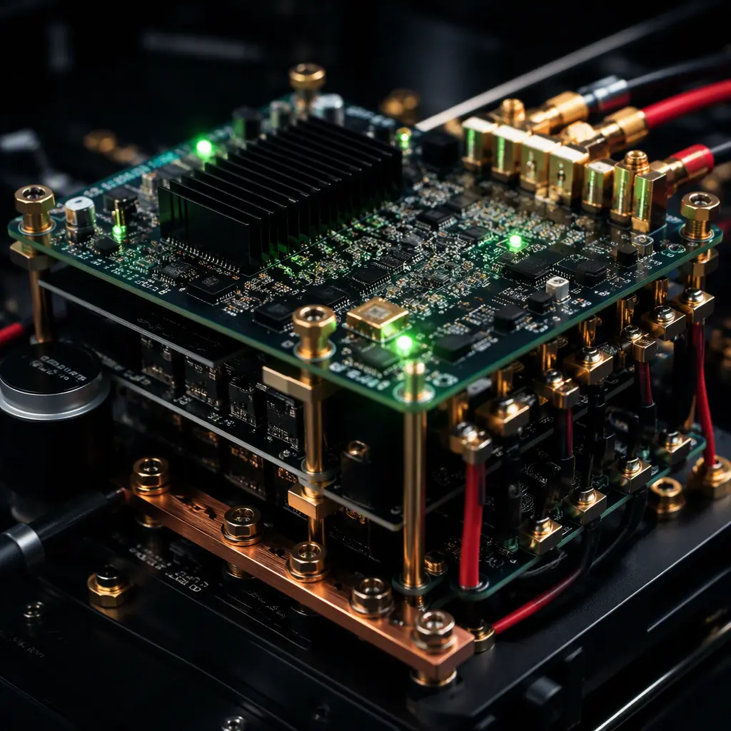
Every non-battery energy source needs power electronics to feed the bus, and the quality of that electronics decides how much of the harvested energy reaches the motors. Three components dominate:
- MPPT (maximum power point tracking). Solar cells have a single operating point at which they deliver peak power, and it moves with irradiance, temperature and partial shading. An MPPT controller: typically 95–98% efficient. Continuously hunts that point; a fixed-voltage connection without MPPT leaves 20–40% of the panel's capability on the table. The MPPT input must match the panel string voltage and the output must match the bus voltage, which is why the payload power budgeting guide treats the bus as a single design object rather than a collection of converters.
- Generator rectifier and bus interface. The alternator's three-phase output is rectified and regulated to the bus voltage. The critical spec is transient behavior: when the payload or motors draw a surge, the generator must hold the bus without droop or overshoot, and it must never back-feed the engine. A diode-OR or active-OR interface between generator, solar and battery is the standard way to keep sources isolated on one bus.
- DC-DC converters. The regulated rails for avionics (5 V, 12 V) and payloads sit between the main bus and the loads; on a hybrid platform they must handle a wider input range than on a pure-battery platform because the bus voltage varies with generator state. The connectors and power distribution guide covers the wiring, fusing and connector side of this same bus architecture.
 Concept illustration
Battery sizing in a hybrid architecture: the buffer, not the tank
In a hybrid architecture the battery changes role: it stops being the energy tank and becomes the buffer that absorbs transients the generator cannot follow. The sizing rules change with it. The battery must cover the difference between peak demand (takeoff, climb, payload surges) and generator output. For a 500 W generator on a platform that peaks at 1,200 W in climb, the battery must deliver the 700 W gap for the duration of the climb plus a reserve. It must also absorb regenerative energy and provide the quiet, generator-off flight modes (stealth, no-fly-zone loiter) that many operators specify.
The practical result is a battery one-third to one-half the size of the pure-electric equivalent, sized on power rather than energy . The battery management guide covers the C-rate and cycle-life implications, because a hybrid battery cycles far more often than a mission battery and its cycle life becomes the maintenance driver. The payload power budgeting guide provides the budgeting method: sum the load profile, subtract the generator and solar contributions, and the residual defines the battery's required energy and peak current. This is the calculation that turns a hybrid platform from a marketing claim into a mission plan.
The trade-offs: weight, drag, complexity and failure modes
Every architecture pays for its endurance in a currency the procurement team must budget explicitly:
- Weight. The generator, fuel and solar cells all displace payload or battery mass. The break-even is a mission-math question: the endurance gained must exceed the endurance lost to the extra mass the aircraft must carry. For a 20 kg platform, a 2.5 kg generator buys 4–10× endurance; the trade is almost always positive for endurance-critical missions and negative for short-range operations where the mass would be better spent on payload.
- Drag. Solar cells on the wing add surface drag and weight at the worst location, outboard, where bending loads concentrate. The airframe materials guide is the reference for how the wing structure must change to carry the panel mass without a stiffness penalty.
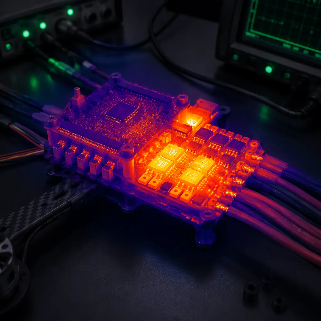
- Complexity and reliability. A hybrid adds an engine, fuel system, alternator, rectifier, MPPT and a more complex bus: each with its own failure modes. The safety and redundancy guide covers how redundancy architecture changes when the propulsion chain includes a mechanical engine, and the thermal management guide covers the engine and electronics cooling that is a leading cause of hybrid field failures.
- Maintenance. Engines have hours-based maintenance intervals, fuel systems need cleaning, solar cells degrade with UV exposure and need cleaning. The spares and lifecycle planning guide is the framework for converting these intervals into a parts and labor plan.
The failure-mode summary for procurement: a battery-only platform fails electrically and predictably; a solar platform fails softly (endurance shrinks with weather); a hybrid platform fails mechanically and needs the same maintenance discipline as any combustion asset; a fuel cell platform fails on logistics before it fails on hardware. Each fleet's operating environment picks the answer.
Procurement: specifying a hybrid-capable power system
When the mission math favors an extended-endurance architecture, the RFQ should carry six clauses:
1. Mission profile and energy budget. The flight profile (climb, cruise, loiter, descent) with power draw per phase and the target endurance. Verification: the supplier's energy budget calculation, cross-checked with the method in the payload power budgeting guide.
2. Architecture declaration. Whether the platform is battery-only, solar-augmented, series hybrid or fuel cell, and the delivered energy density in Wh/kg at the bus. Verification: the system block diagram and the measured (not theoretical) efficiency figures.
3. Generator performance. Continuous and peak output, specific fuel consumption in g/kWh, start time, and the transient response when loads surge. Verification: the generator test report.
4. Power electronics efficiency. MPPT efficiency across the operating irradiance range, DC-DC efficiency at the operating points, and bus voltage tolerance. Verification: the measured efficiency curves.
5. Thermal management. The cooling solution for the engine, alternator and electronics, and the operating temperature band. Verification: the thermal test data, the thermal management guide is the reference for the test method.
6. Maintenance and support. The hours-based maintenance schedule, the spares kit for the generator and fuel system, and the support commitment. Verification: the maintenance plan, aligned with the spares and lifecycle planning framework.
The certification and compliance guide adds the regulatory layer: a combustion engine changes the transport and import classification of the platform, fuel transport is regulated on both ends of the shipment, and the compliance documentation must cover the generator as well as the airframe. The extended endurance is only valuable if the platform is legal to deploy where the mission operates.
Explore custom engineering Back to Blog
Both the power distribution hardware and the hybrid propulsion builds are built in-house at EMS Drone, which means the interfaces between them are specified by the same team. Review the hardware we manufacture if you are scoping a build, or read how we handle the adjacent subsystem.
Continue Reading
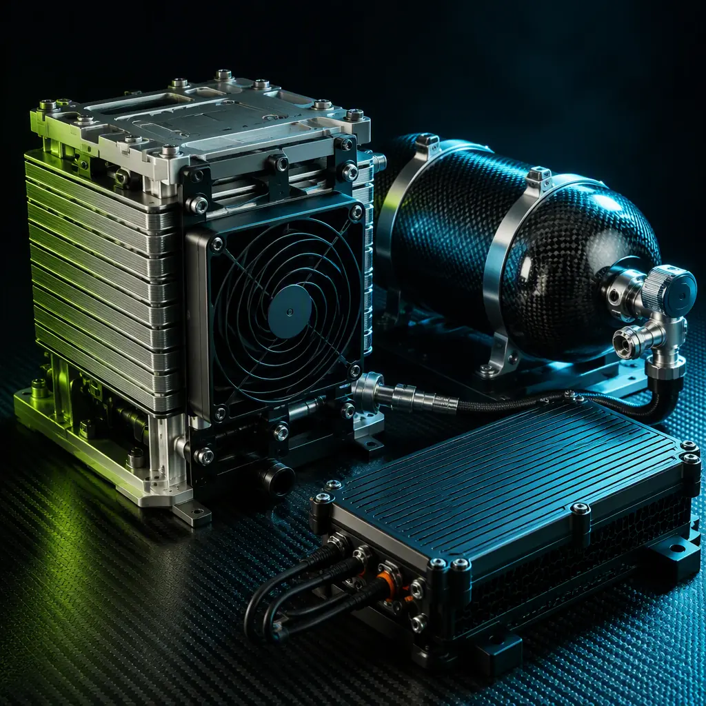
UAV Hydrogen Fuel Cell Propulsion
The fuel-cell alternative to the hybrid generator, stack, tank and balance-of-plant architecture with its own energy-density and logistics trade-offs.
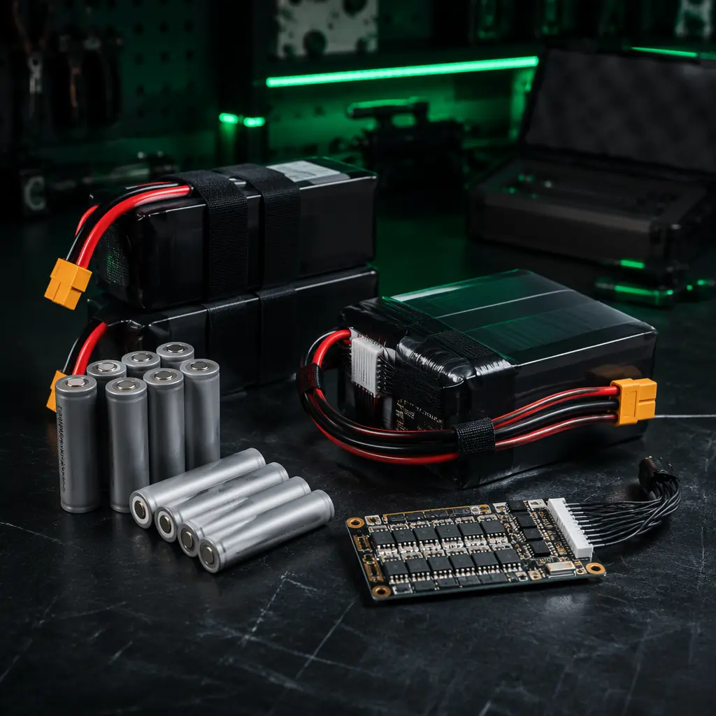
UAV Battery and Power Management
LiPo vs Li-Ion chemistry, cycle life and charge management, the lithium baseline every extended-endurance architecture builds on.
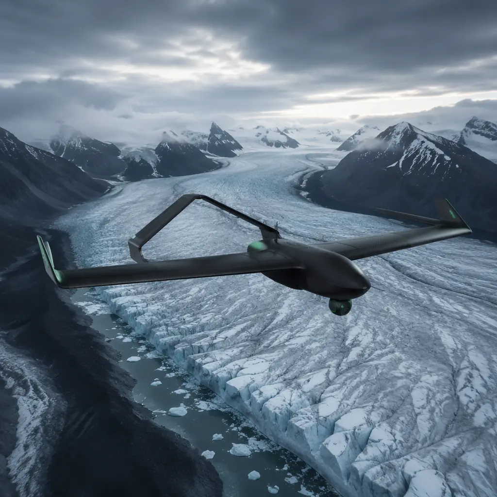
UAV Components for Environmental Monitoring
Solar-assisted long-endurance airframes in real remote deployments. Where augmentation pays back and where it does not.
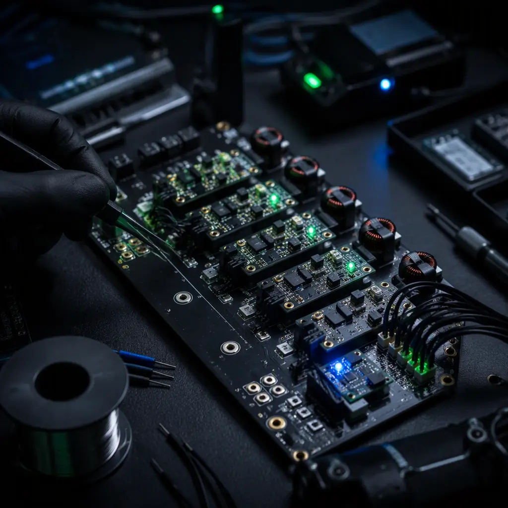
UAV Payload Power Budgeting
Regulators, filters and sequencing on the shared bus, the method for sizing the battery buffer in a hybrid architecture.
Thermal Management for UAV Electronics
Engine, alternator and electronics cooling, the first-order design constraint on hybrid and solar-augmented airframes.