
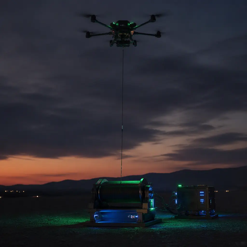
Tethered UAVs occupy a specific niche in the endurance landscape: they cannot roam, but they do not land. The environmental monitoring components guide describes the aerostat alternative for stationary sensing; the tethered multirotor sits between the aerostat and the free-flying aircraft. Faster to deploy than an aerostat, persistent where a battery platform is not.
When tethered beats batteries and swap logistics
The endurance comparison is blunt. A typical industrial multirotor with a 30,000 mAh LiPo flies 30-60 minutes; a fleet running swap logistics can sustain a presence for hours at the cost of packs, chargers and people. A tethered system with a 5 kW ground unit flies indefinitely, limited only by maintenance intervals:
- Persistent surveillance and security. Public safety incidents, a barricade situation, a search perimeter, a VIP movement, need eyes for hours, not sorties. The public safety components guide covers the mission profile; the tether removes the battery change from the critical path entirely.
- Communications relay and counter-UAS. A tethered aircraft at 80-120 m acts as a relay mast for tactical radios or a persistent observation post for counter-drone operations. Defense users value the same attributes: endurance, a predictable hover position and a ground point that cannot be hijacked by RF jamming of the downlink alone. The defense and security components guide frames the reliability requirements.
- Continuous data collection. Traffic monitoring, event coverage and environmental sampling over a fixed point benefit from a stable, vibration-managed hover for hours on end, without the sensor duty cycle being interrupted by landings.
The trade is mobility: a tethered aircraft is anchored within its tether radius, and the ground station must travel with the mission. When the requirement is "watch this point for eight hours", that trade is almost always worth it.
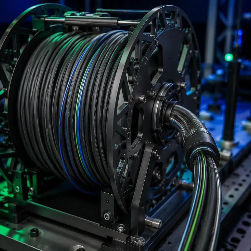 Tether cable
The tether cable: power conductors, fiber and the voltage-drop math
The tether is the heart of the system, and its design is a chain of compromises between weight, resistance and data capacity:
- High voltage keeps the cable light. Power delivered over the tether is distributed at high voltage, commonly 300-600 V DC, so the cable can carry kilowatts with thin conductors. At 400 V, a 2 kW aircraft draws 5 A; at 24 V the same power needs 83 A and a cable thick enough to anchor a boat. The onboard power module converts the high voltage back to the 12-24 V rail the aircraft actually uses.
- The voltage-drop budget. Every conductor has resistance, and at 100-200 m of tether the drop is real: a 400 V feed over a 150 m tether with a 1 Ω round-trip resistance loses about 5 V at 5 A, under 2%, acceptable. The same math at 48 V would lose over 10%, which is why tethered systems do not distribute low voltage. The drop budget, not the cable rating, sets the maximum tether length for a given aircraft power draw.
- Data path. Modern tethers embed single-mode or multimode fiber alongside the power conductors for a jamming-immune, high-bandwidth data link, thermal video, multi-channel audio and flight telemetry all at once. A tether with only copper data pairs limits bandwidth and picks up EMI from the power conductors beside it.
- Construction and weight. The tether is a load-bearing member: it carries its own weight, the aircraft's pull in gusts and the winch tension. Aramid or Kevlar strength members, tight-strand conductors and a ruggedized jacket determine both the cable's mass (which the aircraft must lift) and its life (which the operator must replace).
The connectors, wiring and power distribution guide covers the connector and isolation practice on the aircraft side; the tether is the same discipline extended to 150 m and exposed to weather.
Power-over-tether architecture: the ground unit and the onboard module
The electrical architecture splits into two conversion stages, and each is a sourcing decision:
- Ground power unit (GPU). The GPU takes mains or generator power and outputs the regulated high-voltage DC that feeds the tether. It includes the isolation transformer or isolated DC-DC stage, surge protection, and the current-limiting that protects the aircraft if the tether is damaged. A 3-8 kW GPU covers typical tethered multirotors with payload; the GPU's efficiency and power factor matter when the system runs for days on a generator.
- Onboard power module. At the aircraft end, a compact DC-DC converter steps the high voltage down to the flight rail: typically 12 V or 24 V, sometimes a direct 48 V bus for high-power platforms. The converter must isolate the aircraft ground from the tether ground (ground loops through a 150 m cable are a real interference source), tolerate the voltage transients of connector mating, and fail in a mode that lets the aircraft switch to battery without a glitch.
- The hybrid battery role. Tethered aircraft still carry a small battery. For the transition to tether power, for gusts that exceed the tether's current budget momentarily, and as the emergency energy source for a controlled descent if the tether is cut. The payload power budgeting guide shows how to size that hybrid energy buffer alongside the mission payload.
Slip rings: the rotating joint that keeps the tether alive
The aircraft yaws continuously in flight, fighting wind, tracking a target, orbiting a point, and every full rotation would twist the tether into a spiral. The slip ring is the component that lets the airframe rotate freely while the tether stays stationary:
- Electrical paths. A tethered UAV slip ring carries the high-voltage power path (or a low-voltage power path plus sensing), multiple data channels (Ethernet, serial, video) and often a fiber-optic rotary joint alongside the electrical rings. Each channel is a brush-and-ring contact pair with its own contact resistance and current rating.
- Continuous rotation rating. A persistent system may rotate hundreds of times per day, every day. The slip ring's brush life, measured in millions of revolutions, and its sealed construction against dust and moisture set the maintenance interval. A ring rated for intermittent rotation fails early in continuous service.
- Noise and data integrity. Brush contact noise can corrupt the data channels if the rings are not properly segregated and shielded from the power rings. The specification should state the data channel's bit-error performance while the ring rotates at operating speed, not just at rest.
- Redundancy. The slip ring is a single point of failure for the entire persistent capability. High-end systems dual-brush critical channels or design the ring block for quick field replacement, because a slip ring failure on station means the aircraft lands immediately.
The ground control station hardware guide covers the ground-side integration the slip ring connects into; the two are specified together because the data protocol and the rotation behavior are coupled.
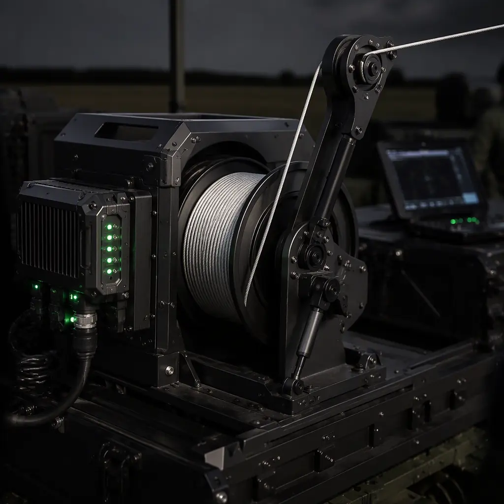 Winch & tether management
The winch and tether management system: tension, spooling and auto-retract
Between the ground unit and the aircraft, the winch, the tether management system (TMS), is what makes long-duration flight practical:
- Active tension control. The aircraft climbs, the wind gusts, the aircraft yaws. And the tether must stay taut without pulling the aircraft off station or letting the cable slack into a snag. The TMS pays out and reels in against a tension setpoint, reacting in real time to the aircraft's position. This is a control loop, not a spool on a motor.
- Spooling quality. A tether with fiber inside cannot tolerate the crushing and abrasion of sloppy spooling. Level-wind mechanisms that lay the cable evenly across the drum, and drum diameters large enough to respect the cable's bend radius, are what keep a fiber tether alive past the first few deployments.
- Auto-retract and fault response. On a tether fault, high wind or operator command, the TMS retracts the aircraft automatically while the aircraft holds altitude on battery. The descent profile and the retract speed must be coordinated with the flight controller, the safety and redundancy systems guide covers how the fail-safe architecture is specified.
- Mobility. For public safety and defense users, the winch is often trailer- or vehicle-mounted with the GPU, turning the whole system into a towable capability that deploys in minutes.
Flight dynamics: payload penalty, altitude and wind
Adding a tether changes the aircraft's physics in ways the propulsion sizing must account for:
- The cable is a constant load. The aircraft lifts the tether's full hanging weight plus the drag of the cable in wind. A 150 m tether weighing 3-5 kg adds that mass to the hover thrust requirement for the entire mission. And the drag grows with wind speed, which is exactly when the operator wants the aircraft steady. Propulsion must be sized for tether-plus-payload at the maximum expected wind, not for the clean aircraft. The powertrain matching guide covers the motor-ESC-propeller sizing method.
- Altitude ceiling. Tethered systems typically operate at 30-150 m. The practical ceiling is set by the voltage-drop budget, the tether weight the aircraft can carry, and the regulatory framework for tethered operations, which varies by jurisdiction.
- Station-keeping quality. The tether pulls the aircraft off vertical when the wind blows, so the flight controller must hold position against a persistent lateral force. RTK or vision-based positioning helps, and the control tuning differs from free flight, the autopilot PID tuning guide explains the gain behavior under a constant external load.
Safety and failure modes: what happens when the tether fails
The tether is a single point of failure, so the system design assumes it will break or be cut:
- Controlled descent on battery. On tether loss, the aircraft must transition seamlessly to battery power and execute a pre-programmed descent. The battery sized for this contingency is not optional. The transition logic lives in the flight controller and the onboard power module together.
- Electrocution and arcing risk. A live 400 V tether cut on the ground is a hazard to people and equipment. The GPU must detect the open circuit and de-energize within milliseconds, and the system design should make the ground end of a severed tether inert by default. This is a safety specification, not an electrical detail.
- Snag and entanglement. A slack tether near trees, antennas or vehicles is an entanglement hazard. The TMS tension control, a minimum operating altitude and site planning are the mitigations; the safety and redundancy guide frames the system-level fail-safe requirements.
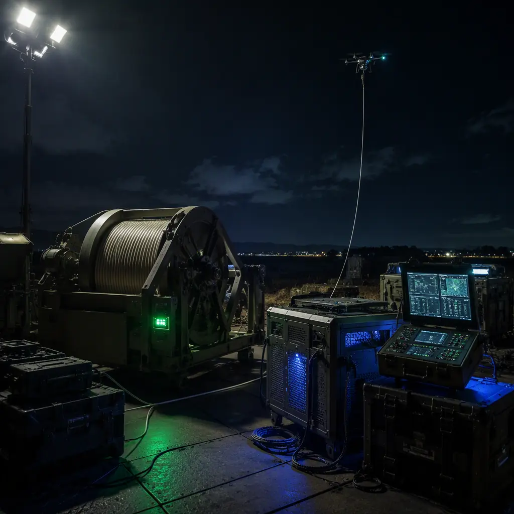 Deployed system
Regulation: remote ID, BVLOS and tethered airspace
Tethered operation is not unregulated operation. The aircraft is still a UAV, and the ground point does not remove the compliance stack:
- Remote ID still applies. A tethered aircraft is still broadcasting its position and identity under most remote ID regimes; the remote ID and BVLOS compliance guide covers the component and integration requirements.
- Tethered exemptions vary. Some regulators treat tethered aircraft as a distinct category with relaxed rules for continuous operation over a controlled site (many waive the visual line-of-sight requirement because the aircraft is physically anchored). Others apply the same framework as free flight. The operating jurisdiction must be checked before the system is procured, because the regulatory treatment affects the GPU site plan, the altitude limit and the crew requirements.
- Airspace integration. In controlled airspace the tethered aircraft is still a traffic item; the UTM and detect-and-avoid integration guide covers how the persistent platform fits the wider airspace picture.
Tethered system procurement checklist
- Endurance and duty cycle. Define the required hours-per-deployment and days-per-year; they set the GPU rating, the maintenance plan and the slip ring life specification.
- Tether specification. Length, voltage-drop budget at the aircraft's worst-case power draw, fiber data capacity, breaking strength and bend radius. With the cable weight stated, because the aircraft must lift it.
- Electrical architecture. GPU input (mains, generator or vehicle), output voltage, isolation, surge protection and de-energize-on-fault behavior; onboard module output rail and the hybrid battery buffer size per the payload power budgeting method.
- Slip ring. Power and data channel count, continuous-rotation brush life, sealed construction and data integrity at speed.
- TMS. Tension control range, spooling mechanism, auto-retract behavior and coordination with the flight controller's fail-safe.
- Flight dynamics. Propulsion sized for tether-plus-payload at maximum wind, and the station-keeping/positioning solution.
- Compliance. Remote ID integration, tethered exemptions in the operating jurisdiction and the crew/ops manual.
The bottom line: a tethered UAV system is a ground-to-air power and data chain, cable, slip ring, winch, converters, with an aircraft attached, and every link must be specified to the same standard as the aircraft itself. Buy the endurance your mission actually needs, size the tether and the winch around the worst-case wind, de-energize on fault, and check the jurisdiction before the PO. EMS Drone specifies and integrates tethered platforms: the tether and slip ring selection, the ground power unit and onboard conversion, the winch integration with the flight controller, and the persistent-operations documentation package. Send the mission profile, endurance, altitude, payload and operating region, and we will respond with the tethered system specification.
Explore Communications & RF Back to Blog
Continue Reading
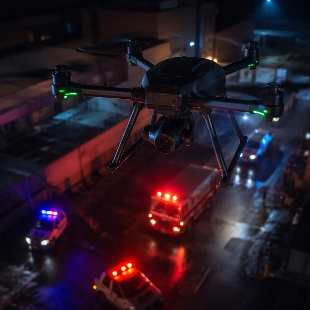
Public Safety Components
The persistent-surveillance missions a tethered platform supports.

Defense & Security Components
The reliability standard tethered systems are held to.
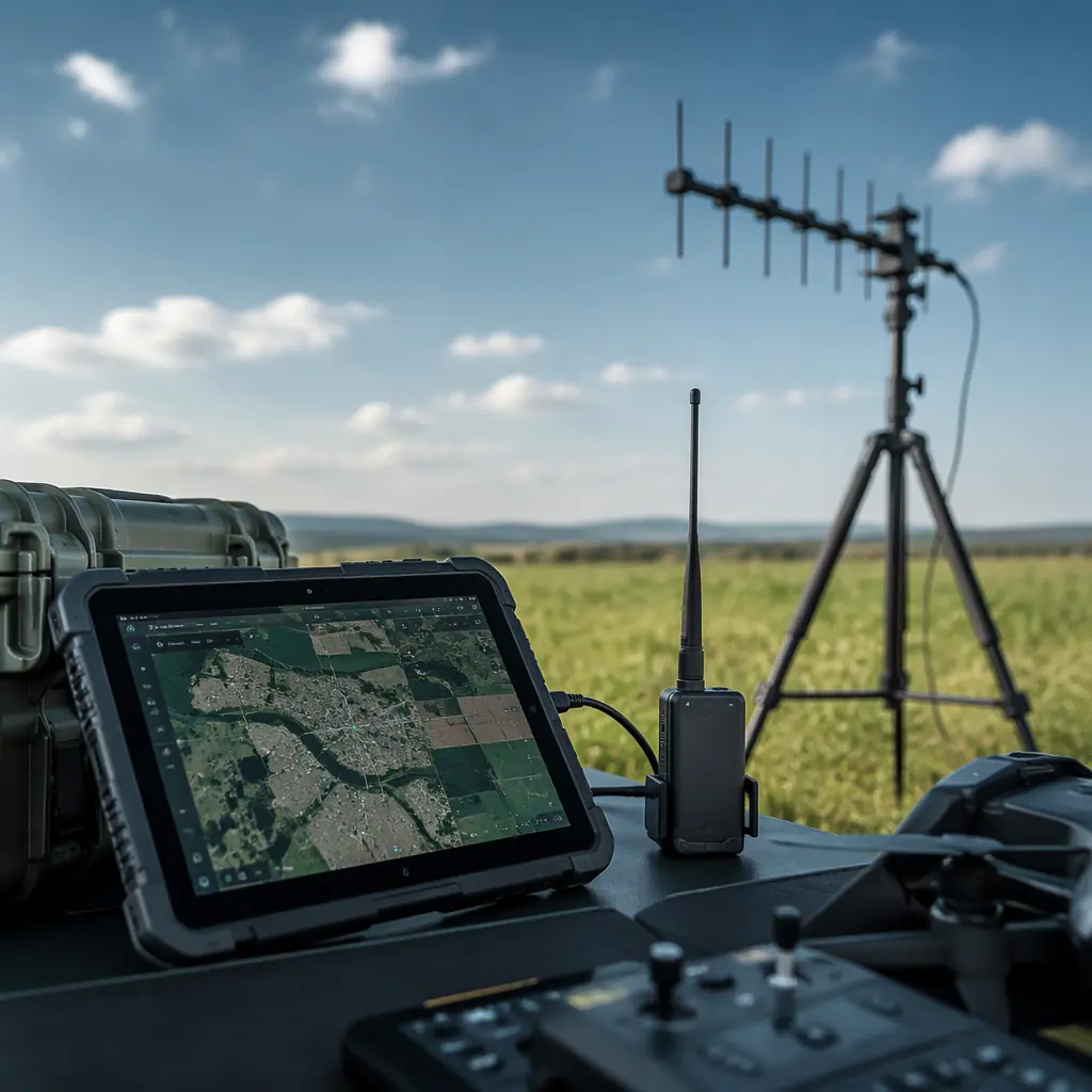
Ground Control Station Hardware
The ground-side integration the winch and GPU plug into.
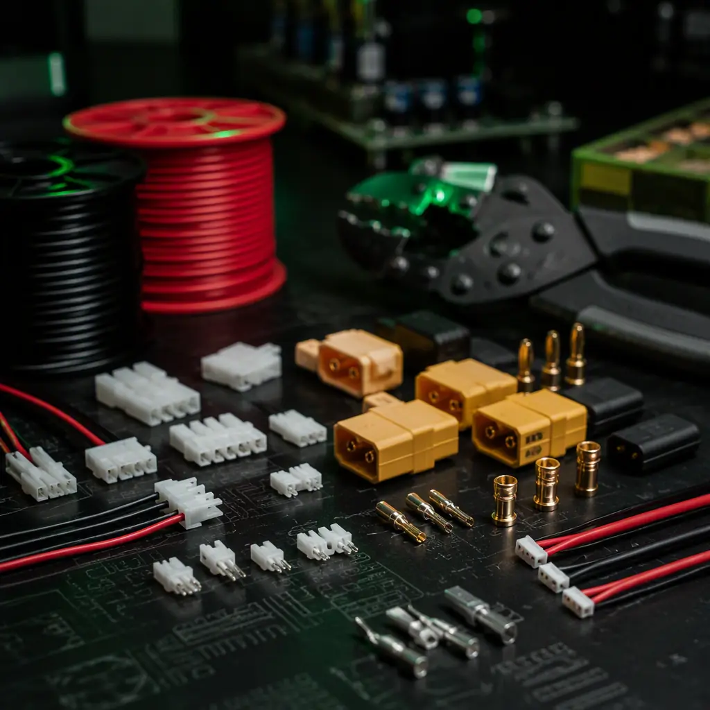
Connectors & Wiring
Isolation and connector practice the tether chain shares.
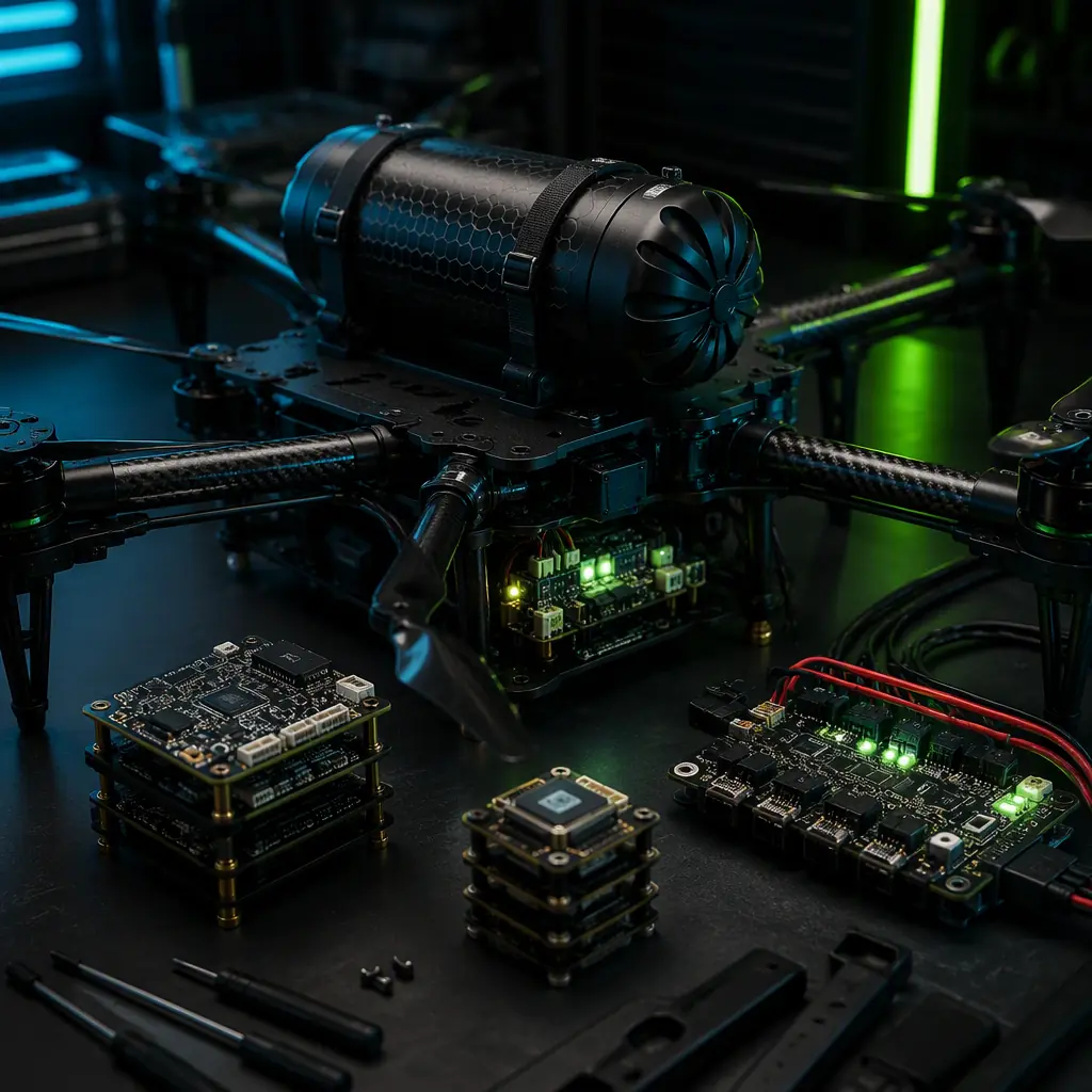
Safety & Redundancy Systems
The fail-safe architecture for tether-loss and fault response.