
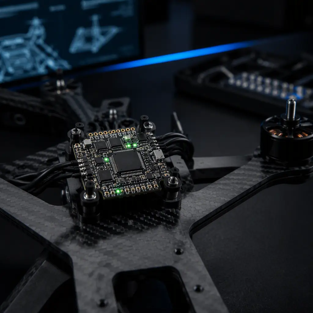
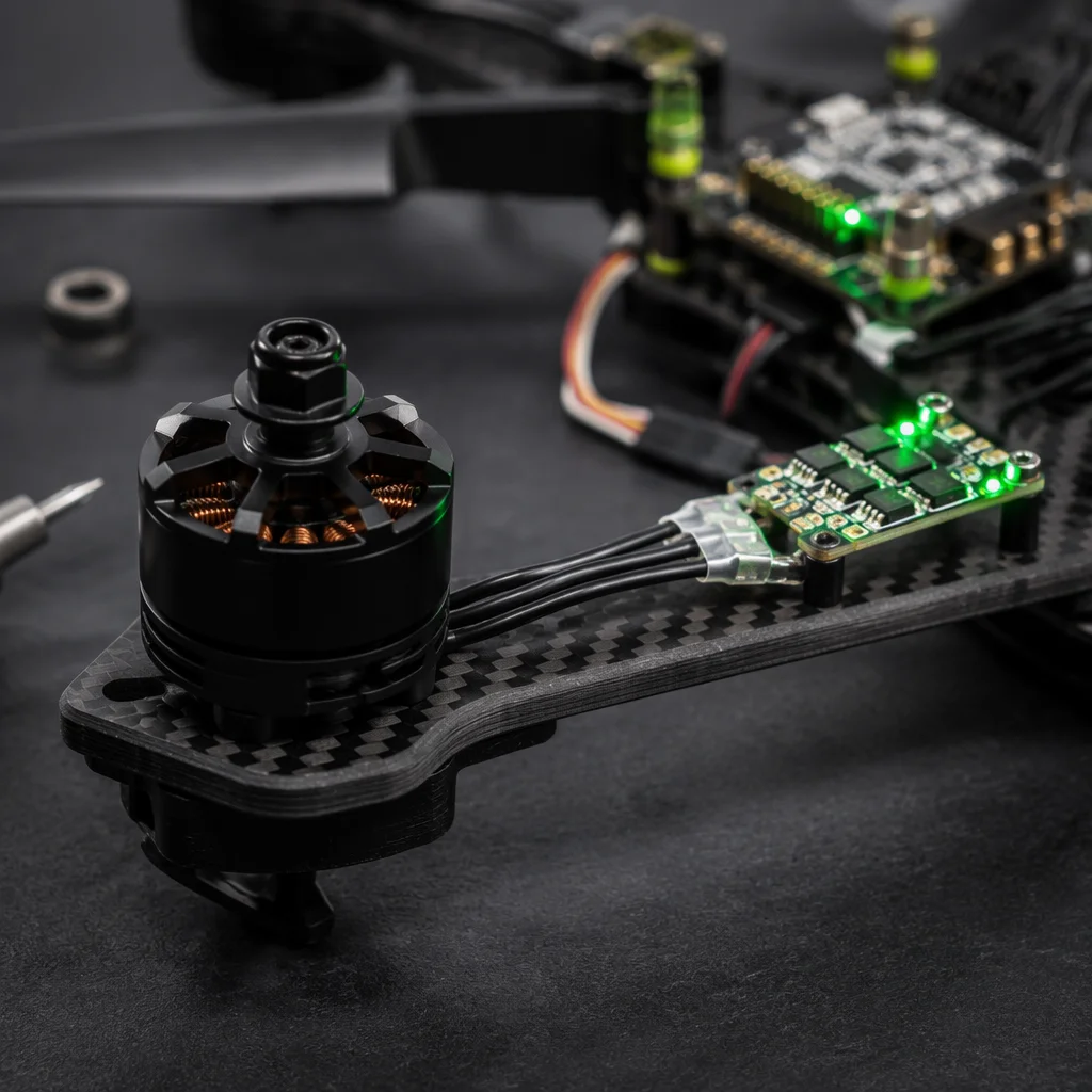
Tuning is the process of matching the controller's gains to the aircraft it controls. The aircraft, the "plant" in control theory, is a chain of physical components: the flight controller writes a throttle command, the ESC interprets it over a digital or PWM protocol, the motor converts it into torque, the propeller converts torque into thrust and angular acceleration, the airframe responds, and the IMU measures the result. Every link in that chain adds latency and changes the response the controller sees. A gain set that worked on a 7-inch racing quad with 2306 motors will not fly the same on a 22-inch heavy-lift platform with 100 KV motors, not because the software changed, but because the plant changed. This is why the powertrain matching guide treats the FC, ESC and motor as one system: the tuning envelope is the output of that system.
Why PID tuning starts with component selection, not software
Buyers and integrators usually inherit a tuning problem the same way: the aircraft flies, but it wobbles in hover, oscillates at speed, or drifts in the wind, and the first instinct is to change gains. Before changing gains, change the question: is the controller fighting a component that is outside its expected envelope? Three component decisions dominate the tuning envelope:
- ESC protocol and update rate. A PWM ESC updates at 50-490 Hz, while a DShot 600/1200 ESC updates at the control loop rate or faster, with a checksum on every frame. The update latency difference, roughly 2-20 ms for PWM versus under 1 ms for DShot 1200, sits directly inside the loop the PID is closing. The ESC firmware guide compares BLHeli_32, AM32 and FOC firmwares on exactly this axis, and the communication protocols guide covers the timing of CAN, DShot and PWM in detail.
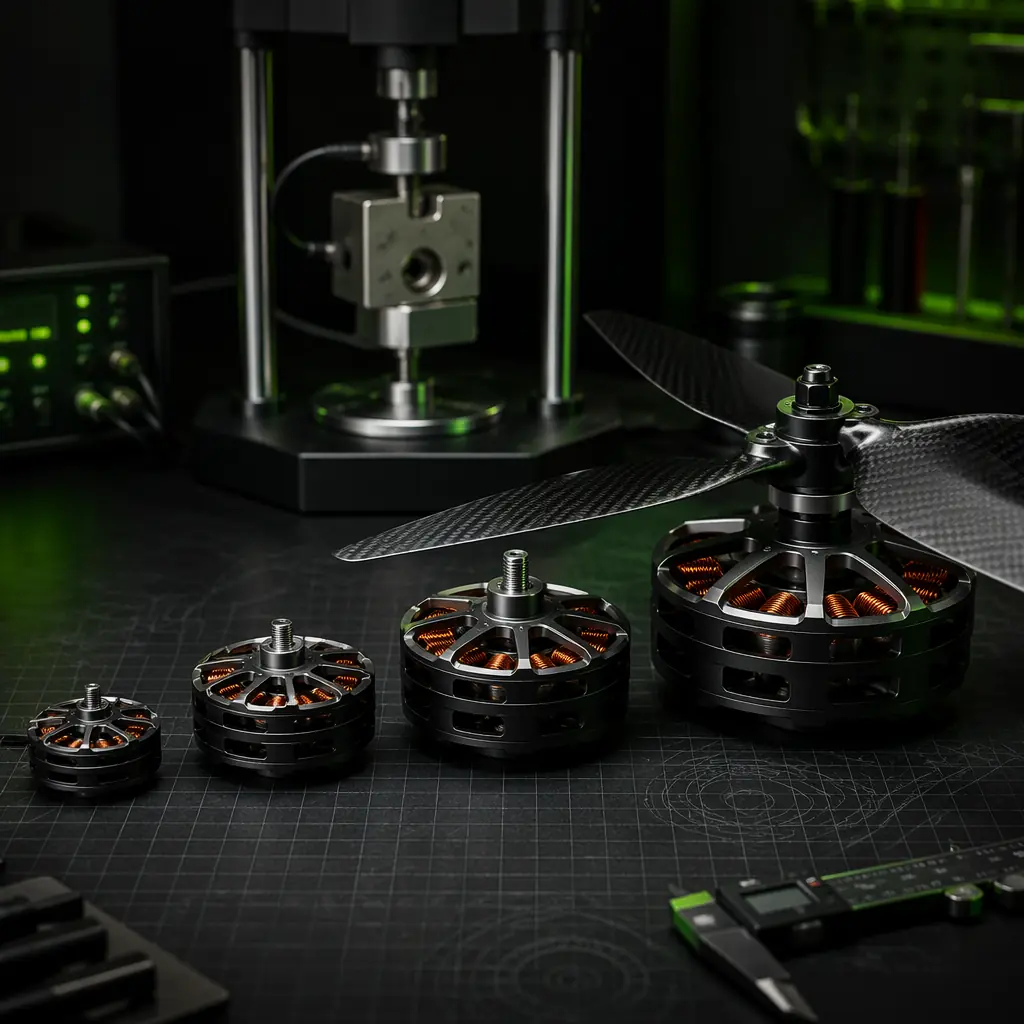
- Motor response time. A motor's ability to change speed is set by its electrical time constant and the inertia of the rotor plus propeller. High-KV motors with small props respond in milliseconds; low-KV motors swinging large props take tens of milliseconds to spool. The controller's rate-loop gains must be sized to the slower of the two, the motor KV selection guide quantifies the trade.
- Airframe stiffness. Flexible arms put structural resonance in the 20-60 Hz range that the gyro sees as noise. A tune that is stable on a rigid carbon frame can fight a flexible frame's resonance and oscillate. The airframe materials guide explains why stiffness per gram differs so much between carbon, aluminum and G10.
The practical consequence: if the components are mismatched, no gain setting fixes it, the build versus buy guide makes the same argument for the stack as a whole. A matched propulsion set with a baseline tune flies after an afternoon of gain adjustment; a mismatched set can consume weeks and still fly badly.
The control loops: rate, attitude and position, and the gains inside each
A UAV autopilot runs three nested control loops, and each has its own PID gains:
- The rate loop is the innermost loop. It measures angular velocity from the gyro and commands torque from the motors. Its P gain sets how hard the aircraft resists rotation, its I gain removes steady-state bias (asymmetric props, an off-center CG, or ESC calibration offsets), and its D gain damps oscillation by reacting to the rate of change. The rate loop runs at the full control rate, 1 kHz on a modern flight controller.
- The attitude loop sits outside the rate loop. It measures the angle from the attitude estimator (fused from gyro, accelerometer and magnetometer) and commands the rate the aircraft should rotate at. Its gains are typically lower than the rate gains, and it runs at the same 1 kHz cadence or slower.
- The position loop is the outermost loop. It compares GNSS position against the mission plan and commands attitude. It runs at 5-50 Hz and is far more forgiving of gain errors, but it cannot fix a marginal rate loop, it inherits everything below it. The mission planning guide covers the flight modes this loop serves.
The gains are hierarchical: position errors flow down as attitude commands, attitude errors flow down as rate commands, and the rate loop is the only one that directly touches the motors. Most oscillation problems live in the rate loop, which is why tuning always starts there and works outward.
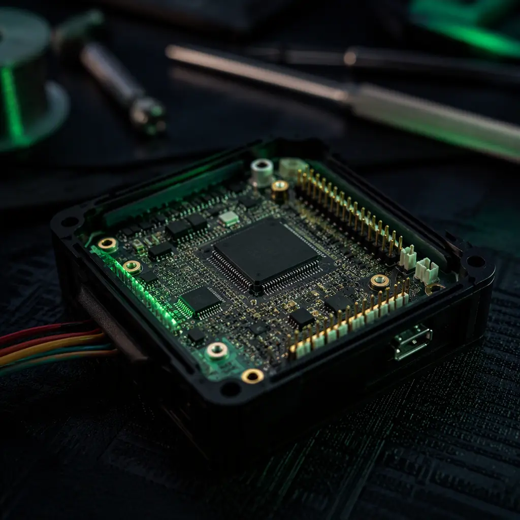 Flight controller and IMU
Loop rates and latency: what 8 kHz IMU and 1 kHz control actually buy you
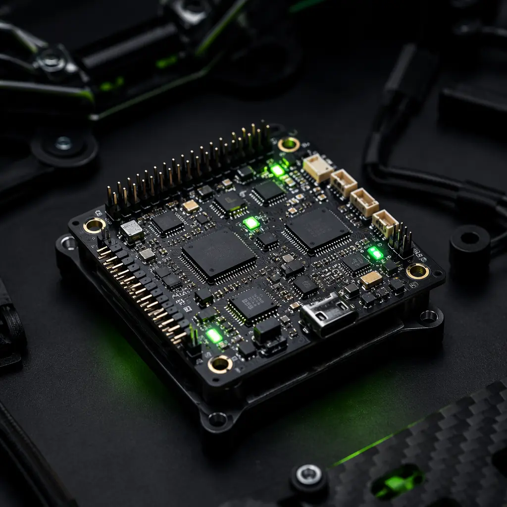
EMS Drone's standard flight controllers sample the IMU at 8 kHz and run the control loop at 1 kHz. Those numbers matter because the controller closes the loop on a budget of phase lag: every millisecond of latency between measurement and torque reduces the phase margin at the crossover frequency, and once the margin goes negative, the loop oscillates.
- The latency budget. Total loop latency = IMU read time + filtering delay + control computation + protocol transmission + ESC processing + motor response. On an 8 kHz IMU with a 1 kHz loop, the read and compute contribution is around 1-2 ms; a DShot 1200 ESC adds under 1 ms; the motor adds 5-30 ms depending on inertia. The motor, not the flight controller, is usually the largest term. Which is why matching propulsion is a tuning input.
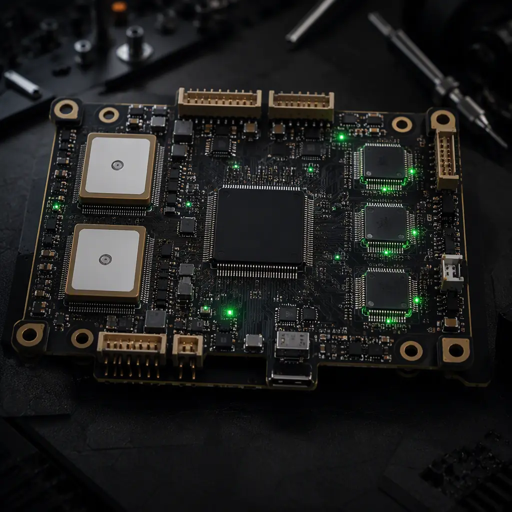
- Filtering versus phase. Gyro noise is filtered before the control loop, and every filter adds phase lag. A notch filter at the propeller frequency (typically 80-200 Hz on large multirotors) removes resonance with a narrow, phase-friendly notch; a heavy low-pass filter removes noise but also removes phase margin. The sensor fusion guide covers how the IMU data quality feeds the estimators that sit upstream of the control loops.
- Where more rate stops helping. Above roughly 1 kHz, the multirotor control loop gains little: the motor response and airframe dynamics dominate the phase budget, not the compute time. Fixed-wing aircraft with slow control surfaces run the same loop at lower rates without penalty. The number that matters is the total phase lag, not the headline sampling rate.
The heavy-lift propulsion guide shows what happens to these dynamics at scale: as rotor inertia grows, the motor response time grows, the usable rate-loop bandwidth shrinks, and the gains must come down to stay stable. A heavier aircraft is not just slower, it is fundamentally harder to tune.
How ESC, motor and propeller choices move the tuning envelope
Each propulsion component shifts the tuning envelope in a predictable direction. Knowing the direction tells you what to expect before the first flight:
| Component change | Effect on the plant | Tuning consequence |
|---|---|---|
| PWM ESC → DShot 1200 | Update latency drops from ~2-20 ms to <1 ms | Rate P gain can rise; loop feels tighter |
| Higher KV, same prop | Faster motor response, lower torque authority | Faster initial response; risk of prop-flutter at high gain |
| Larger propeller | More inertia, slower spool, more thrust per RPM | Lower rate gains; more I gain for trim; more phase lag |
| Low-KV + large prop | Slow response, high torque | Stable but sluggish; attitude P raised to compensate |
| Flexible airframe arms | Structural resonance in the 20-60 Hz band | Notch filter required; rate P limited by resonance |
| FOC ESC firmware | Torque-controlled motor, fast field-oriented commutation | Very fast inner response; gains sized for torque control |
The pattern is that every component decision trades bandwidth against authority. A stack tuned by the supplier on the actual airframe class, the EMS Drone matched-stack approach described in the flight controller and ESC matching guide . Starts from a known envelope instead of discovering it in the field.
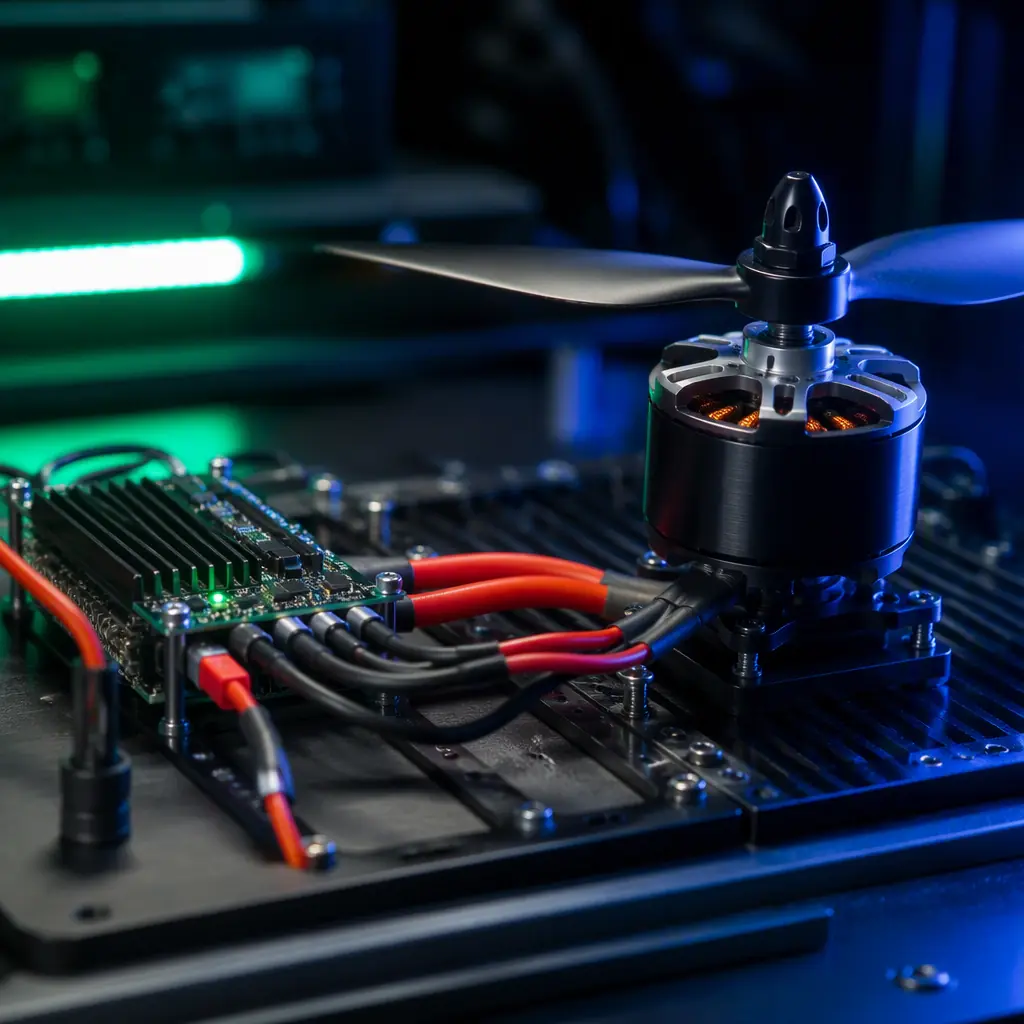 ESC and motor bench
Tuning methods: manual gains, software autotune and frequency sweeps
Three approaches cover the spectrum from field-fix to laboratory-grade, and professional programs use all three at different stages:
- Manual gain stepping. The classic sequence: start with conservative rate P, fly, and raise it until the aircraft oscillates; back off to roughly 70% of the oscillation threshold; add I to remove steady-state drift; add D last to damp the remaining overshoot. Each step is one flight or one hover test, and the observable symptoms are the guide, the propulsion testing guide describes the test instrumentation that makes those observations quantitative instead of subjective.
- Software autotune. ArduPilot's AutoTune and PX4's automated tune inject excitation and estimate the gains from the response: typically a 5-15 minute flight that replaces hours of manual stepping. The ArduPilot versus PX4 guide compares how the two stacks implement this, including the frequency-sweep mode that flies a series of commanded oscillations and fits the plant model.
- Frequency sweeps and system identification. The rigorous method: command a swept excitation (a chirp) on each axis, record the gyro response, and fit the gain and phase as a function of frequency. The targets are textbook numbers: roughly 6 dB gain margin and 45 degrees of phase margin at crossover. This is the method that produces a documented, repeatable tune. And it is the method behind supplier baseline tunes.
Before any of these methods touch real air, a simulator run, software-in-the-loop or hardware-in-the-loop, covered in the HIL testing guide . Validates that the gain structure is sane and the aircraft is not borderline unstable. Good tuning practice is a pyramid, not a single flight.
Reading the symptoms: what oscillation, overshoot and drift tell you
Diagnosis starts with the flight behavior, but the evidence lives in the blackbox log. The common symptom map:
| Symptom | Most likely cause | First move |
|---|---|---|
| High-frequency oscillation at hover (audible buzz) | Rate P too high, or D amplifying noise | Cut rate P by 30%; check gyro noise in the log |
| Low-frequency bobble, 1-3 Hz | Attitude P too high relative to rate loop | Reduce attitude P; verify rate loop margin first |
| Overshoot on attitude steps | D too low, or rate saturation | Raise rate D; check commanded vs actual rate |
| Constant lean or drift in one direction | Trim, CG offset, or ESC calibration | Re-calibrate ESCs and check CG before touching I |
| Wobble in prop wash or after aggressive turns | I gain windup or filter lag | Set I limits; check filter cutoff in the log |
| Resonant flutter at a fixed frequency | Structural resonance beating with the loop | Notch filter at the FFT peak; check arm stiffness |
The fastest diagnostic is an FFT of the gyro rate in a hover log: a single sharp peak at the propeller frequency says "notch filter", a broad rise at low frequency says "attitude loop", and broadband noise says "filter or D gain". The multirotor versus fixed-wing guide is a reminder that the same symptom can have different causes on different architectures. A fixed-wing bobble at speed is often elevator authority or CG, not gains.
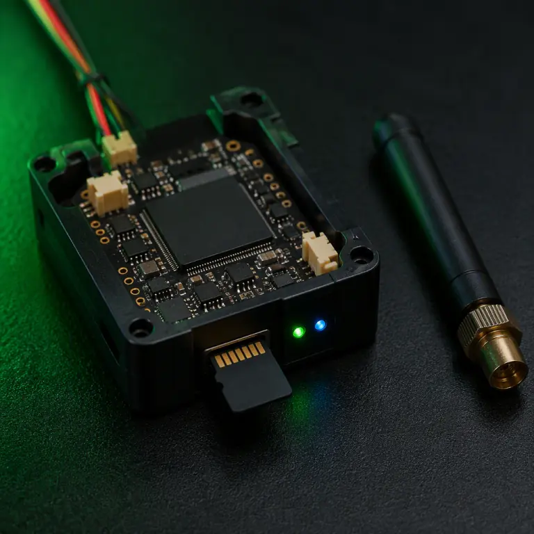 Blackbox data logging
Acceptance criteria: putting tuning in the procurement specification
A tuned aircraft is a testable artifact, and the specification should say so. Measurable acceptance criteria that belong in an RFP or supplier agreement:
- Hover stability. Attitude deviation within ±2 degrees in calm conditions with no sustained oscillation, and no visible wobble at hover, verified over a two-minute logged hover.
- Step response. A commanded attitude step of 15-20 degrees settles with less than 20% overshoot and within 1.5 seconds, from the log, not from observation.
- Gust behavior. Attitude hold within ±5 degrees in 5-8 m/s wind, with no divergent oscillation. Wind response exposes marginal rate margins that hover hides.
- Deliverables. The gain tables, filter settings and a representative blackbox log for the exact airframe class, plus the tuning method used (manual, autotune or frequency sweep). The component RFP guide shows how to turn these into clauses with test methods, and the supplier evaluation checklist covers the questions to ask about tuning support.
The final rule: PID tuning is not a software problem bolted onto a hardware purchase. It is the acceptance test for the whole stack. Buy from a supplier that matches the propulsion set, pre-tunes on the airframe class, and ships the gains, filters and logs with the aircraft. That documentation is the difference between a stack you tune for weeks and a platform that flies on day one. EMS Drone supplies flight controllers and matched propulsion stacks with baseline tunes per airframe class, loop rates, filter settings, gain tables and flight logs included, with remote tuning support for integration programs. Send the airframe class, propulsion set and mission profile, and we will specify the flight controller stack that tunes clean the first time.
Explore Flight Controllers Back to Blog
Continue Reading
ArduPilot vs PX4 Autopilot
How the two open-source stacks implement autotune and frequency sweeps.

ESC Firmware: BLHeli_32 vs AM32 vs FOC
The ESC response characteristics that set the inner-loop envelope.
UAV Powertrain Matching
FC, ESC and motor as one system, the plant the gains must match.
UAV Motor KV Selection
How KV and rotor inertia set the motor's place in the loop.
UAV Sensor Fusion & Redundant Navigation
The estimators upstream of the control loops, and what feeds them.