
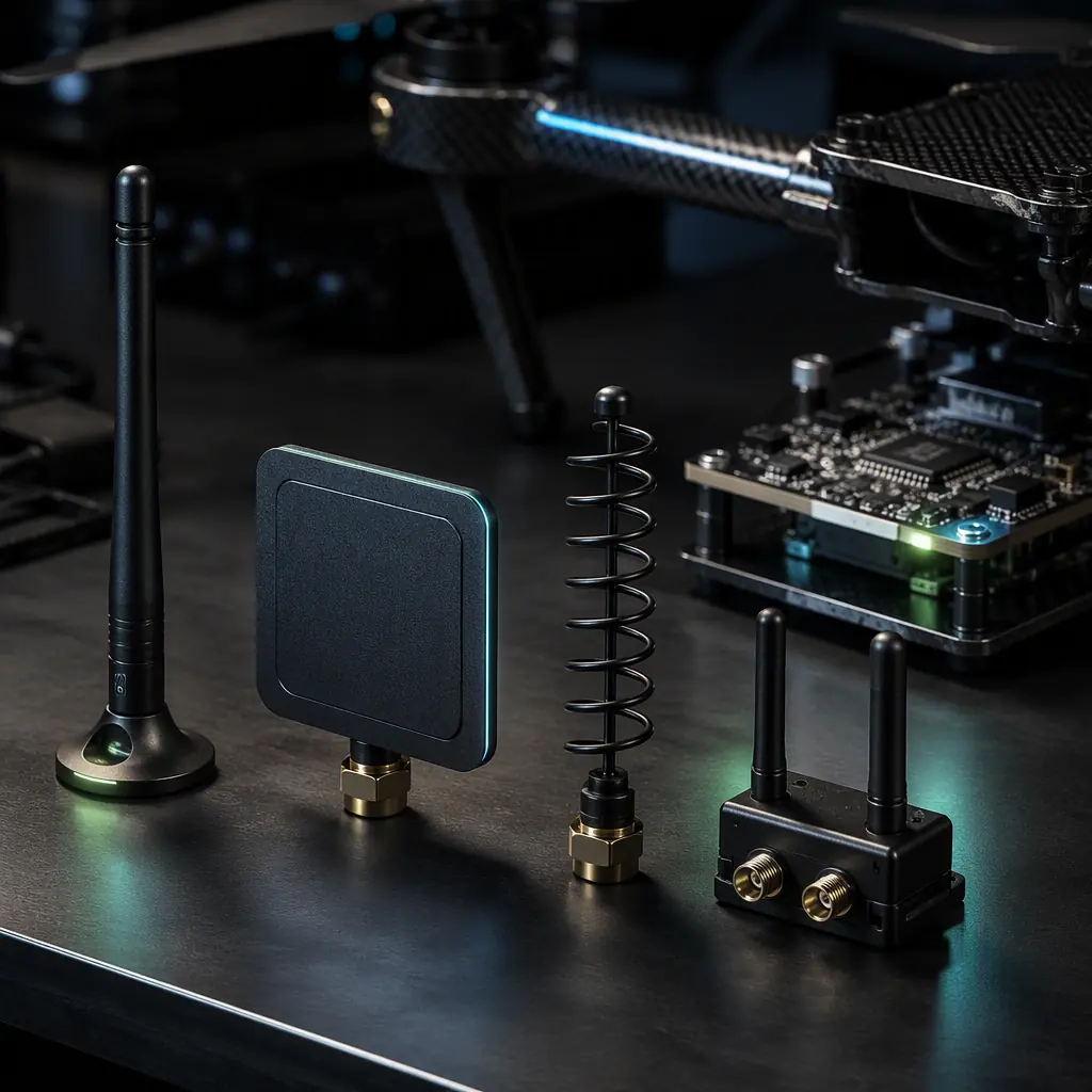
An antenna is the only component in the RF chain that converts watts into free space. And the only one that costs less than the cable connecting it. On industrial UAVs the antenna is also the most abused component: mounted near a conductive carbon fiber frame, vibrating for hundreds of flight hours, dragged through rain, dust and salt spray, and expected to work at both ends of a 30 km link. The UAV RF communication systems guide covers the frequency bands and the link budget framework; this guide covers the physical antenna, the type, the gain, the placement and the losses that decide whether that link budget ever becomes a real connection.
Why the antenna decides the link budget
Every decibel in a UAV link budget either comes from transmitter power, receiver sensitivity, path loss, or antenna gain, at both ends. The free-space path loss at 915 MHz over 10 km is about 112 dB. A typical telemetry radio delivers +20 dBm (100 mW) and a receiver sensitivity around -110 dBm, leaving roughly 18 dB for antenna gain, cable loss, polarization mismatch and fade margin combined. Two antennas at 3 dBi each and a clean cable give you 6 dB back; a bad cable, a mismatched polarization and a shadowed element take 8 dB away. The difference between a link that holds and a link that drops is entirely inside the antenna system, which is why the communication protocols guide can describe the data side while the physical layer still fails at the antenna.
Antenna gain is also the only free gain in the system: it does not consume battery, generate heat or add weight beyond a few grams. The cost is beamwidth. A higher-gain antenna focuses energy in one direction and must be pointed there. Understanding that trade-off is the difference between selecting an antenna and guessing at one.
 Antenna types
Antenna types: omnidirectional, patch, helical and MIMO
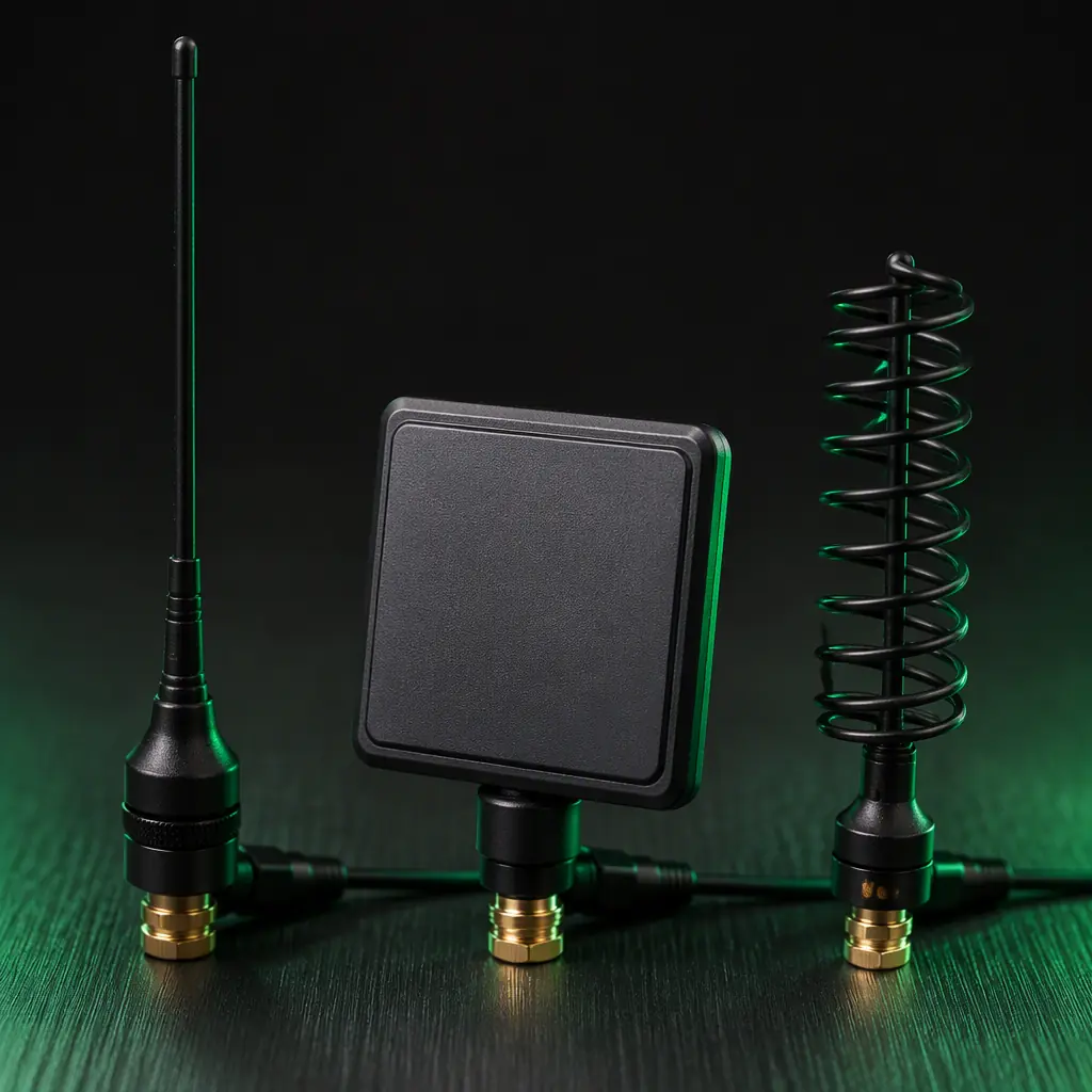
Industrial UAVs use four antenna families, and each fits a specific role in the link architecture. The choice starts with the radiation pattern you need, not with the datasheet gain number.
| Type | Typical gain | Pattern | Best role on a UAV |
|---|---|---|---|
| Omnidirectional whip / monopole | 0-3 dBi | 360° around the axis | Telemetry, RC control, Remote ID, any link where aircraft attitude changes |
| Dipole | 2-3 dBi | Donut around the element | Same roles, slightly higher gain, needs ground clearance |
| Patch (microstrip) | 5-8 dBi | Hemispherical, one face | GNSS reception on top of the airframe; downlink pointing when flat-mounted |
| Helical (axial mode) | 8-14 dBi | Narrow beam, circularly polarized | Video downlink and long-range data links on a gimbal or tracker |
| MIMO / multi-element arrays | 3-9 dBi + diversity gain | Multiple patterns, switched | 4G/LTE and Wi-Fi links where multipath and orientation vary |
The pattern matters more than the peak gain number. A mapping UAV banking into turns with a high-gain directional antenna on the fuselage will point its beam at the horizon half the time; a 2 dBi whip that covers the full sphere of aircraft attitude is worth more than a 9 dBi panel that only works level. The FPV and video downlink guide shows how the same logic applies to the video link, where the ground station antenna usually does the high-gain work and the aircraft side stays omnidirectional.
Gain and beamwidth: reading past the datasheet number
Antenna datasheets quote gain in dBi, decibels relative to an isotropic radiator, but the number is only half the story. Gain is beamwidth converted into concentration: a 3 dBi omnidirectional antenna spreads energy over a sphere, a 10 dBi helical squeezes it into a cone of roughly 55° to 60°. The relationship is physical, and it cannot be cheated. A compact "12 dBi omni" that is 10 cm long on 868 MHz is either not 12 dBi or not omni.
- Beamwidth budget. For a fixed-wing aircraft with a stabilized antenna mount, a 10-14 dBi helical with a 40-60° beam is usable because the mount keeps the beam on the ground station. For a multirotor with a fixed fuselage antenna, the useful gain is closer to 3-5 dBi because aircraft attitude swings the pattern by 30° or more in normal flight.
- Ground plane dependence. A monopole's gain and pattern assume a ground plane beneath it. On a carbon fiber or aluminum airframe the fuselage can serve as that plane. But only where the antenna is actually mounted on the conductive surface, not dangled below it on a cable. A whip mounted on a plastic bracket over a non-conductive area behaves like a detuned dipole with a tilted, lossy pattern.
- Efficiency versus gain. Small antennas at 433 MHz and 868 MHz are electrically short. A quarter-wave monopole at 868 MHz is about 8.6 cm, and antennas compressed into 3 cm for a compact airframe trade radiation efficiency for size. A "3 dBi" stub that is a fifth of a wavelength long is often delivering -2 dBi of real performance. The honest spec is radiation efficiency, and few hobby-grade datasheets publish it.
The rule for procurement: specify the frequency, the pattern requirement (omnidirectional or directional), the physical envelope, and the minimum realized gain with the matching network included, then test, rather than trusting the marketing gain. The ground control station guide covers the ground-side antennas that complete the same budget.
Polarization: the 3 dB that disappears without explanation
Polarization mismatch is the most common silent link killer. A vertical whip transmitting and a horizontal whip receiving lose roughly 20-30 dB of signal. The link is gone and nobody changed a single setting. Two more common cases:
- Linear versus linear, rotated. Two linear antennas at 45° to each other lose about 3 dB. In a banking turn, a vertical aircraft antenna and a vertical ground antenna can rotate relative to each other by the bank angle, costing several dB exactly when the aircraft is maneuvering.
- Linear versus circular. A circularly polarized antenna receives a linearly polarized signal with a fixed 3 dB loss, regardless of orientation. That is why helical antennas and RHCP (right-hand circular polarization) patch antennas are standard on video downlinks: the 3 dB penalty buys immunity to aircraft attitude, and the 10-14 dBi gain of the helical absorbs the penalty and still comes out ahead.
The practical rule: match polarization between aircraft and ground station, prefer circular polarization for anything that maneuvers or rotates, and document the polarization of every antenna in the system. Mixed linear and circular links lose 3 dB before a single meter of distance is added. The GNSS module selection guide covers the same logic on the positioning side, where a circularly polarized GNSS antenna is required by the signal format itself.
 Airframe placement
Placement on a carbon fiber airframe: ground planes and shadowing
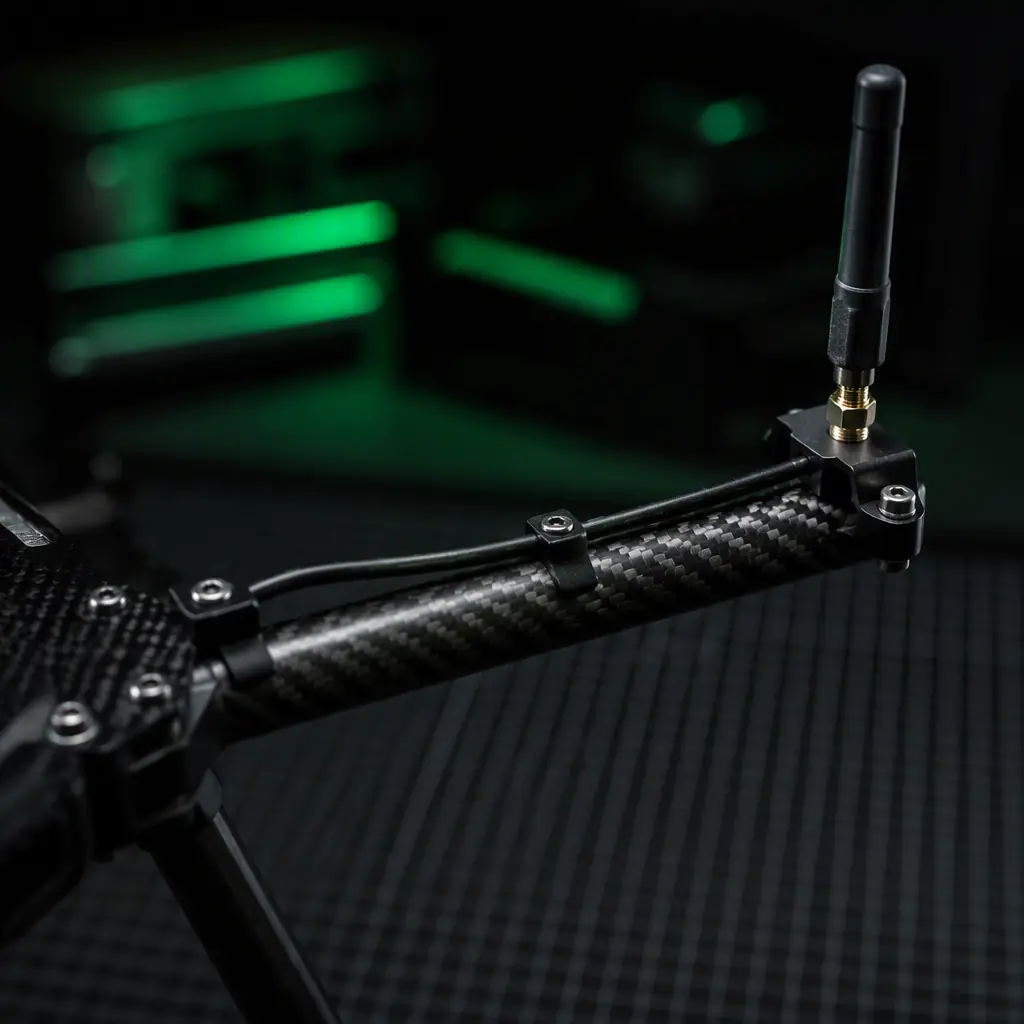
Carbon fiber is conductive, roughly 1,000 to 10,000 times more resistive than copper, but conductive enough to act as a shield, a detuning element and an unintended reflector. Placement rules on composite airframes are therefore not cosmetic; they decide whether the antenna radiates at all.
- Shadowing. A carbon fiber fuselage between the antenna and the ground station attenuates the signal by 10-30 dB depending on frequency and layer count. The rule is line of sight: the antenna must see the ground station from the aircraft's normal flight attitude, with the fuselage, battery, payload and landing gear out of the direct path. Mounting the telemetry antenna on the underside of a multirotor with a belly payload is a guaranteed range reduction.
- Ground plane quality. If the antenna needs a ground plane, the plane must be a continuous conductive surface under the element. Carbon fiber works, but the contact between the antenna's ground and the frame must be electrical, not just mechanical, painted, anodized or resin-rich surfaces insulate. A dedicated aluminum or copper ground plane plate under the antenna is the reliable engineering answer.
- Antenna separation. Multiple transmitters on one airframe, telemetry at 915 MHz, video at 2.4 GHz or 5.8 GHz, GNSS at 1.5 GHz, interfere through their antennas. The practical separation rule is half a wavelength or more between elements (about 16 cm at 915 MHz, 6 cm at 2.4 GHz), with the GNSS antenna highest and clearest because it receives the weakest signal. The GNSS anti-jamming guide adds the interference-hardening angle to the same placement problem.
- Cable routing. The coax must not run parallel to power wiring for long runs, and must be strain-relieved at both ends. Vibration fatigue is the leading cause of intermittent RF failure on airframes. The connectors and wiring guide covers the harness-side rules that keep the RF cable clean.
Cables and connectors: the loss you can measure
Antenna gain is free; cable loss is the tax. A 3 dB antenna gain and a 3 dB cable loss cancel each other exactly. And most UAV builds buy the antenna and forget to check the cable. Measured losses at 2.4 GHz:
 Cable and connectors
| Cable | Loss per meter @ 2.4 GHz | Loss per meter @ 915 MHz |
|---|---|---|
| RG178 (thin, common in UAV builds) | ~1.6 dB | ~1.0 dB |
| RG58 | ~0.7 dB | ~0.4 dB |
| RG400 / RG316 | ~0.5 dB | ~0.3 dB |
| LMR-240 / low-loss | ~0.3 dB | ~0.2 dB |
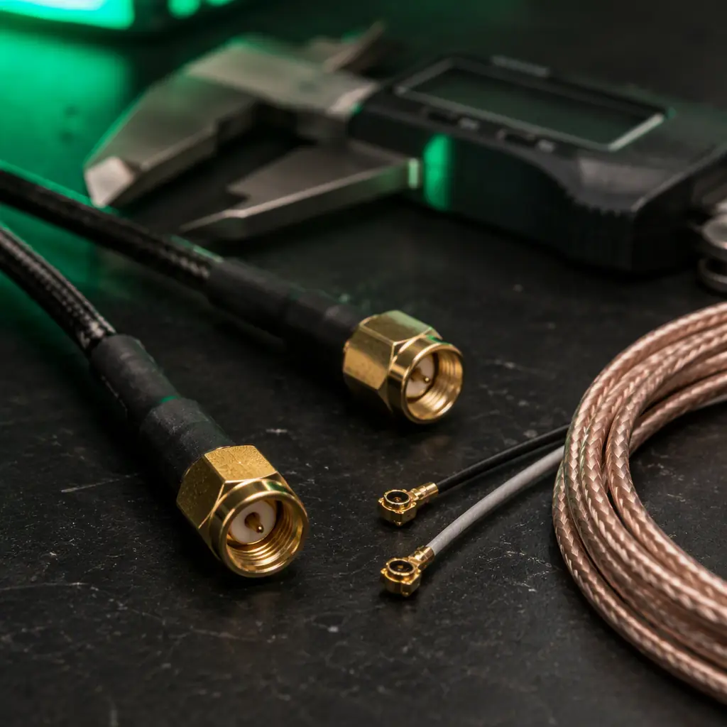
A 30 cm RG178 jumper between a 2.4 GHz radio and its antenna costs about 0.5 dB; a 1.5 m run costs 2.4 dB. More than the gain of the antenna it feeds. The rules: keep RF runs as short as the airframe allows, use the largest cable that fits the bend radius, and check the connector pair. SMA and RP-SMA are mechanically different and the mismatch is a guaranteed 3 dB and a loose joint; U.FL / IPEX pigtails add another connector pair and another 0.2-0.4 dB. Every connector is a loss and a failure point, count them in the budget. The connector selection guide has the full connector family comparison.
Diversity and tracking: when one antenna is not enough
For missions that demand the link hold through attitude changes, shadowing and multipath, single-antenna systems hit a ceiling. Two architectures raise it:
- Receive diversity on the ground. Two ground antennas separated by several wavelengths, feeding a radio that selects the stronger signal, recover most of the loss from polarization rotation and multipath nulls. This is standard on long-range video and telemetry ground stations and costs nothing in aircraft weight.
- Aircraft-side diversity. Two elements mounted at right angles (or one horizontal and one vertical) with an RF switch, selecting the better signal as the aircraft banks. This is the aircraft-side equivalent of the ground diversity and recovers the 3 dB polarization rotation loss in turns.
- Antenna tracking. A gimbal-mounted high-gain ground antenna that follows the aircraft converts the 10-14 dBi helical gain from a pointing liability into a 10-14 dB advantage over the whole mission. Tracking is the standard solution for fixed-wing BVLOS flights and long-range inspection missions.
The Remote ID and BVLOS guide and the video downlink guide both depend on these architectures. BVLOS telemetry cannot afford a polarization dropout, and video quality is judged on exactly the frames the link drops.
Antenna procurement checklist
When the antenna set is on the BOM, these are the specifications to put on paper, the same discipline the UAV component RFP guide applies to every component:
- Frequency and bandwidth. Center frequency plus the band you actually use (for example 868 MHz with 2 MHz bandwidth, not "868/915" which is two different tunes).
- Pattern and gain with conditions. "3 dBi omnidirectional, vertical polarization, on a 100 mm ground plane", not just "3 dBi".
- Realized gain and efficiency. Ask for the radiation efficiency or realized gain including the matching network, especially for electrically short antennas.
- Connector and cable. Connector type, cable type and length, and the insertion loss at the operating frequency.
- Mechanical envelope. Length, diameter, mounting hole pattern, weight, and the vibration/thermal rating. An antenna is a mechanical part first on a UAV. The propulsion testing and validation guide shows the test philosophy that applies to antennas too: measure, don't assume.
The final rule: the antenna system, elements, cables, connectors and placement, is worth 3 to 15 dB of link budget, more than any transmitter upgrade. Specify it with the same rigor as the flight controller, mount it with line of sight to the ground station, keep the cables short, match the polarization, and verify the link on a real range before the mission depends on it. EMS Drone matches every RF system, telemetry, video, GNSS, Remote ID, with antennas and cable assemblies selected and tested for the airframe, and provides measured link test data with the matched stack. Send the mission profile and the aircraft geometry, and we will specify the antenna set that closes the budget.
Explore RF & communications Back to Blog
Continue Reading
UAV RF Communication Systems
The frequency bands and link budget framework that antenna selection executes.
FPV and Video Downlink Systems
Where antenna diversity and tracking decide whether the video link survives the mission.
UAV GNSS Module Selection
The circularly polarized GNSS antenna placement rules behind centimeter-level positioning.

UAV Communication Protocols
CAN, DShot, PWM, SBUS and CRSF, the data side of the links antennas carry.
UAV Remote ID and BVLOS
Why the compliance link has the same antenna requirements as the mission link.