
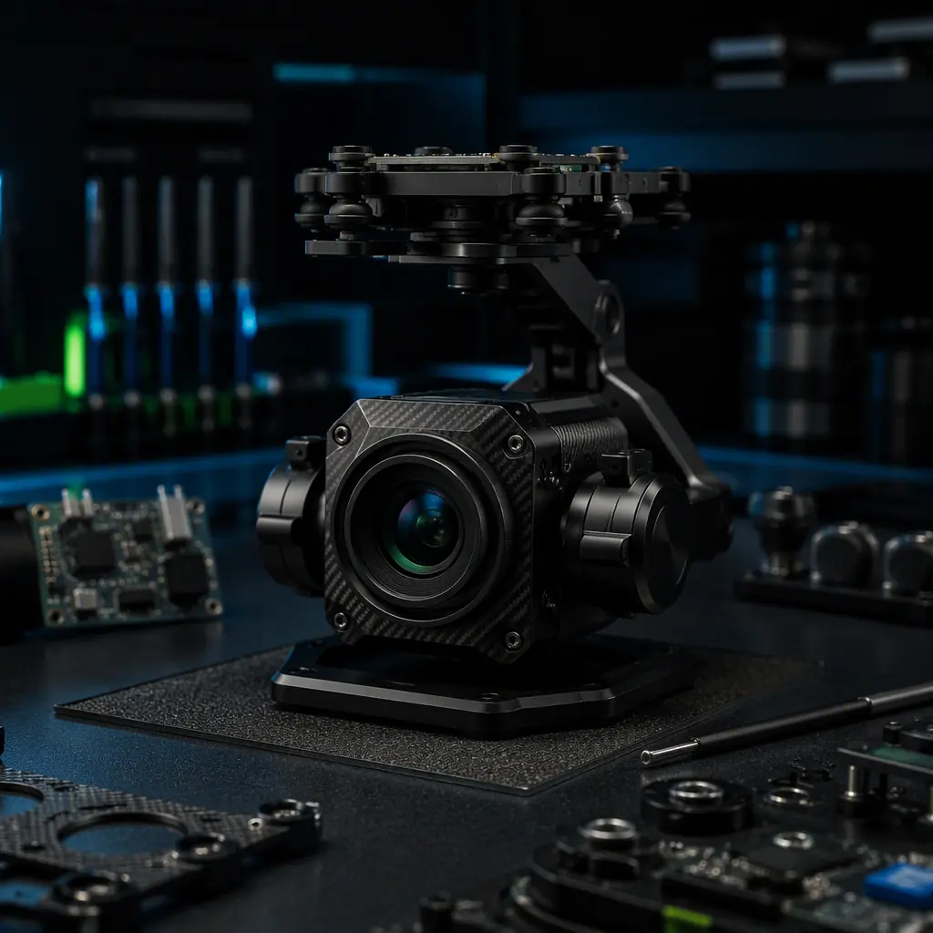
Imaging payloads are the fastest-growing category in industrial UAV procurement, and the least understood. The marketing layer of the camera industry produces megapixel numbers and zoom ratios; the engineering layer works in pixel pitch, focal length, field of view and stabilization error. This guide starts from the mission output — the data product the operator actually needs — and works backward through sensor, lens, stabilization, interfaces and environment to the RFQ. The UAV payload integration guide covers how the payload attaches, powers and communicates with the aircraft; this article covers how to choose the camera and gimbal itself, and the two should be read together because the integration constraints (mass budget, CG, vibration environment) directly bound the selection.
Start with the data product: what the imagery must deliver
The selection discipline starts by naming the data product, because it determines every downstream number. The four common products and their implications:
- Visual inspection stills. An inspector looks at images to find corrosion, cracks, or foreign-object damage. The requirement is ground sample distance (GSD) — the physical size of one pixel at the target distance. A typical inspection spec is 1–5 mm/pixel at the working distance, which directly sets the focal length and flight altitude combination.
- Orthomosaic and survey products. A mapping program stitches thousands of overlapping images into an orthophoto and a digital surface model. The requirement is GSD plus georeferencing accuracy, which adds the RTK/PPK timing link to the camera trigger. The UAV components for mapping and surveying guide covers the GNSS side of this equation.
- Live streaming for public safety. An operator watches a live feed to make decisions. The requirement is resolution plus stabilization plus low-latency video downlink — the imaging chain terminates in the FPV and video downlink systems rather than in a storage card.
- Thermal or multispectral analysis. A thermographer or agronomist measures values from the imagery. The requirement is detector resolution, radiometric accuracy and band selection — numbers that have nothing to do with visible megapixels.
The RFQ should open with the data product statement: "the payload shall produce inspection stills with a GSD of 2 mm/pixel or better at 30 m working distance, georeferenced to ±5 cm." That single sentence forces the sensor, lens and sync decisions in the right order.
Sensor format and the pixel math that actually matters
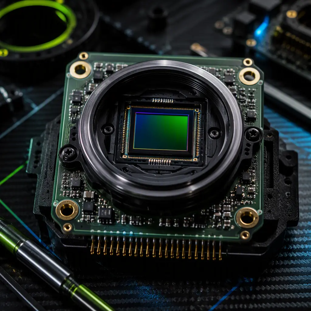
The sensor is the heart of the payload, and the specification starts with two numbers: sensor format (the physical size of the sensor, described by its optical format designation) and pixel pitch (the physical size of one pixel). The megapixel count is a marketing derivative of these two — and the reason the same 20 MP count can mean very different imaging performance.
Format classes and what they change. The common UAV sensor formats, in order of physical size: 1/2.3″ (small, ~6.2×4.6 mm), 1″ (medium, ~13.2×8.8 mm), 4/3″ (large, ~17.3×13 mm), and full frame (36×24 mm). A larger format with the same pixel count means larger pixels, which means more light per pixel — the low-light performance, dynamic range and signal-to-noise ratio all improve. The trade is size, mass and lens cost: a full-frame lens is physically larger and heavier than a 1/2.3″ lens with the same field of view, and the payload mass budget usually decides the argument before the image quality does.
Pixel pitch and the resolution ceiling. Pixel pitch is the number that sets the optical resolution ceiling. A 1/2.3″ sensor at 20 MP has pixels around 1.5 µm; a 1″ sensor at 20 MP has pixels around 2.4 µm; a 4/3″ sensor at 20 MP has pixels around 3.3 µm. Given the same lens, the larger pixels resolve more contrast at the diffraction limit and produce cleaner images in low light. The industrial inspection components guide documents why inspection programs converge on 1″ and 4/3″ sensors — the small-format sensors that look fine in a spec sheet fail on real corrosion and crack features in marginal light.
The aperture and light budget. The lens aperture (f-number) sets how much light reaches the sensor. A lens at f/1.8 passes roughly four times the light of the same lens at f/3.5 — a stop-and-a-half advantage that shows up directly in shutter speed and low-light noise. For moving platforms, the aperture also buys shutter speed: a 1/2000 s shutter freezes vibration blur that a 1/500 s shutter captures.
 Concept illustration
The lens: focal length, field of view and the zoom trade-off
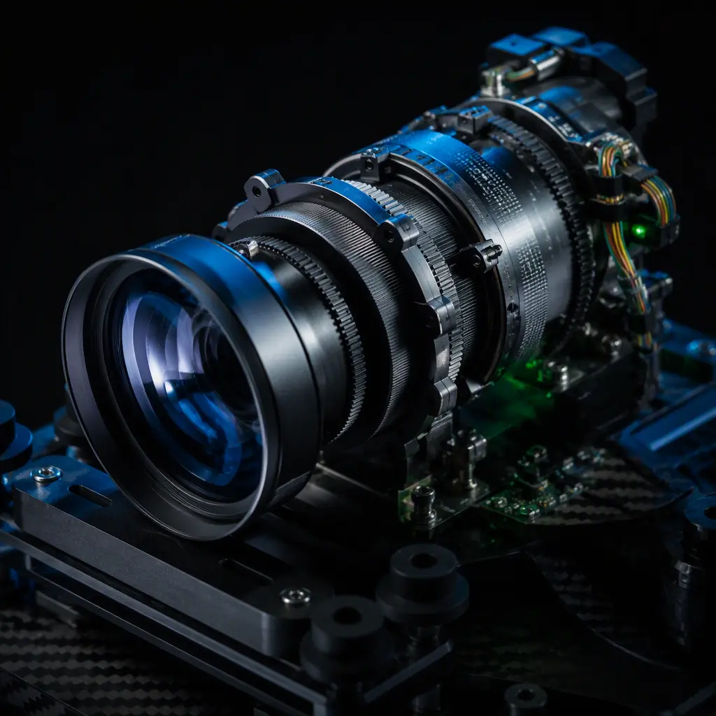
After the sensor, the lens decides what the sensor sees. The two specification numbers are focal length (which sets field of view and magnification) and aperture (which sets light and depth of field), plus the zoom mechanism if the mission needs one.
Focal length and the GSD equation. The relationship that drives everything: GSD = (pixel pitch × working distance) / focal length. For a 2.4 µm pixel at 30 m with a 25 mm lens: GSD = (0.0024 mm × 30000 mm) / 25 mm ≈ 2.9 mm/pixel. To halve the GSD, double the focal length (heavier, narrower field of view) or halve the altitude (closer, more flight time to cover the same area). The focal length selection is therefore always a mission-tactics decision: the same sensor can be specced with a 12 mm wide lens for area mapping or a 40 mm tele lens for inspection detail.
Wide vs tele: the field-of-view math. Field of view (FOV) for a given sensor width and focal length: FOV = 2 × arctan(sensor width / (2 × focal length)). A 1″ sensor (13.2 mm wide) with a 12 mm lens gives about 58° horizontal FOV; with a 40 mm lens it narrows to about 19°. Wide FOV covers area fast; narrow FOV resolves detail. The mission product decides: mapping programs want wide; inspection and surveillance want tele.
Optical zoom vs digital zoom — a hard procurement rule. Optical zoom moves glass and preserves resolution; digital zoom crops the image and destroys it. The rule for the RFQ: any zoom ratio quoted is optical zoom; digital zoom is a post-processing feature, not an optical capability. A "20× zoom" that turns out to be 5× optical plus 4× digital is a 5× zoom — the payload integration guide calls out the same marketing trap in its camera section. If the mission needs long-range detail, spec a true optical zoom lens (10×, 20×) or a fixed tele lens, and treat digital zoom as what it is: a crop.
The lens also carries the focus mechanism — fixed-focus lenses (calibrated for one distance band, common in mapping) vs autofocus (needed for inspection at variable distances). Autofocus adds mass, power and a failure mode; a mapping payload rarely needs it.
 Concept illustration
Stabilization: the gimbal spec that protects the image
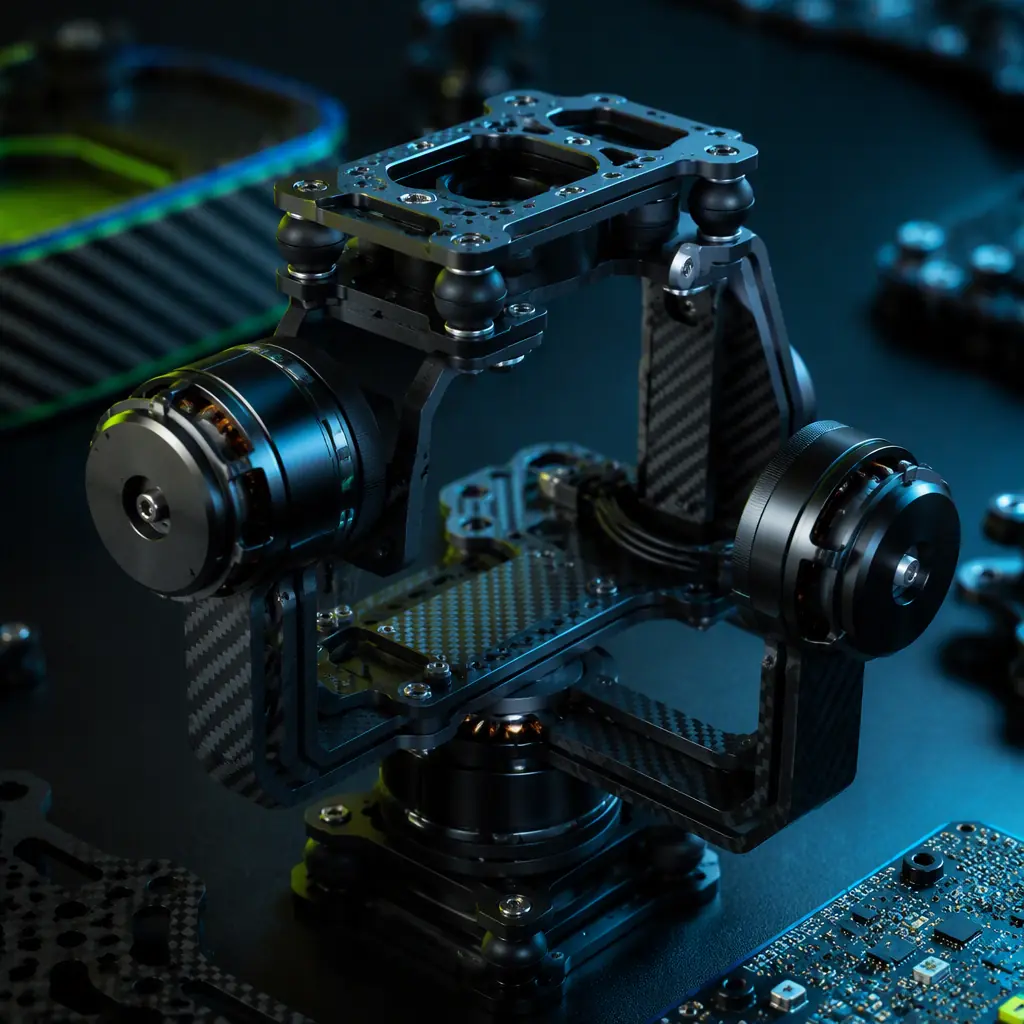
Every camera on a multirotor sees the aircraft's vibration and attitude motion. The gimbal's job is to hold the optical axis steady despite them, and the specification numbers that matter are angular accuracy, axis count, and the damping and isolation between the airframe and the payload.
Angular stabilization accuracy. The headline spec — the residual angular error of the stabilized line of sight, quoted in degrees or millidegrees. A 2-axis gimbal at 0.02–0.05° accuracy is adequate for wide-angle work; a 3-axis gimbal at 0.005–0.01° is the class for long telephoto work, where the same angular error produces a much larger image displacement at long focal lengths. The rule of thumb: the stabilization error in pixels should be a small fraction of one pixel at the mission focal length — the RFQ should state the target ("residual motion less than 1 pixel at the maximum optical zoom") and let the supplier show the math.
Axis count and attitude limits. A 2-axis gimbal (pitch + roll) is the standard for mapping payloads, where the aircraft can be commanded to keep the sensor near-nadir. A 3-axis gimbal (yaw + pitch + roll) is required for surveillance and inspection, where the operator needs to look in arbitrary directions without the aircraft yawing. The pan/tilt limits matter too: inspection of vertical structures (towers, bridges, buildings) needs a gimbal that can look upward — a pitch range of +90° to −120° is common for inspection gimbals.
Vibration isolation. The gimbal's own motors compensate for attitude motion, but the high-frequency vibration from the propulsion system (propeller-induced, motor cogging at 100–500 Hz) must be filtered mechanically. The spec is the isolator design — damped elastomer or spring isolators between the airframe mount and the gimbal body, tuned to attenuate the aircraft's dominant vibration frequencies. The thermal management guide and the airframe articles cover the vibration environment from the structural side; the payload side is the isolator's natural frequency and damping ratio, which should be specified (a natural frequency of 15–30 Hz with 20–40% damping is the typical design target for multirotors).
The gimbal is also an electrical integration point: slip rings for continuous yaw rotation, and the video and control interfaces that run through the gimbal. The UAV connectors, wiring and power distribution guide covers the cabling and connector reliability side — the flexing cables in a gimbal joint are one of the highest-cycle fatigue points on the aircraft.
 Concept illustration
Interfaces and sync: the payload as a data system
The camera and gimbal are not standalone; they are nodes in the aircraft's data network, and the interface specification is where payloads silently fail. The four interfaces that belong in the RFQ:
Video output. The video path to the downlink — HDMI, SDI, Ethernet (RTSP/RTMP) or MIPI CSI for direct connection to a companion computer. The format and latency matter: a public-safety streaming mission needs low-latency (sub-200 ms end to end) H.264/H.265 over Ethernet or HDMI; a mapping mission captures to internal storage and does not stream at all. The FPV and video downlink systems guide covers the downlink side of the chain.
Trigger and sync. For mapping and photogrammetry, the camera shutter must be synchronized with the GNSS position — the trigger event carries the timestamp that anchors each image to its ground position. The spec is a hardware trigger input on the camera (PPS or software trigger with sub-millisecond timing), synchronized with the RTK/PPK solution. The GNSS module selection guide covers the RTK side; the payload side must expose the trigger interface and the exposure-timestamp metadata.
Control interface. The gimbal and camera control protocol — the operator commands (pan/tilt/zoom, record, capture, focus) and the telemetry feedback (gimbal angles, camera status, storage remaining). The protocol should be documented and stable; proprietary control protocols that only work with the manufacturer's own ground software are a long-term integration risk.
Data storage and offload. Onboard storage capacity, write speed and offload method. A mapping mission at 20 MP with 70% overlap over a large area can generate tens of gigabytes per flight — the payload storage and the offload workflow (card, Ethernet, or USB) must match the mission tempo. The UAV edge AI and onboard computing guide covers the companion-computer side, where camera feeds feed real-time processing — and where the interface choice (CSI vs Ethernet vs USB) decides what processing is possible.
Environmental fit: temperature, ingress and the vibration envelope
The payload rides outside the airframe, in the airflow, exposed to the full environment. The three environmental specifications:
- Operating temperature. The payload must work across the aircraft's operating range — typically −20°C to +50°C for commercial operations, with derating behavior specified outside that range. Thermal cameras and their calibration drift with temperature; the thermal management guide covers the electronics side of the same envelope.
- Ingress protection. The payload's IP rating must match the operating environment — IP54 for normal field work, IP65+ for maritime and agricultural spray operations, where the payload is directly exposed to moisture and chemicals. The waterproofing and IP-rated components guide covers the rating system and the test methods in detail.
- Vibration and shock. The payload must survive the aircraft's vibration envelope (typically 5–500 Hz random vibration, and landing shocks of several g) without loosening, fogging or losing calibration. The spec is the vibration test standard (MIL-STD-810 or the RTCA DO-160 vibration curves, which the electronics manufacturing quality guide references for avionics) and the pass criteria: no image degradation, no mechanical damage, no calibration shift.
The environmental fit closes the loop with the airframe: the payload mass, CG and aerodynamic drag change the aircraft's flight performance, and the airframe materials guide and heavy-lift propulsion design guide cover the structural and power side of carrying the payload.
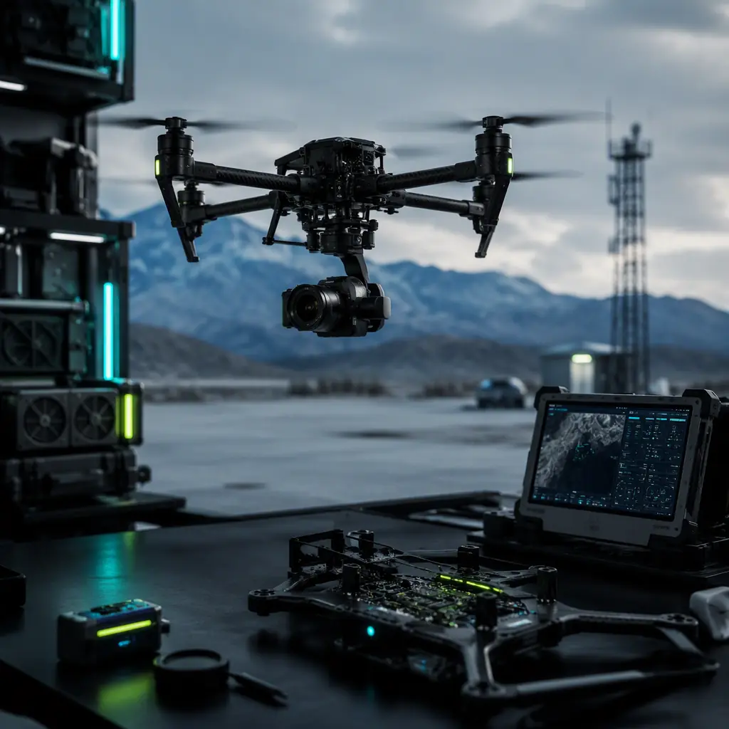 Concept illustration
Mission-specific camera configurations
The generic selection framework resolves differently per mission. The configurations that recur in industrial programs:
Inspection. 1″ or 4/3″ sensor, 20–40 mm tele lens, 3-axis gimbal with upward pitch range, autofocus, and a thermal core (640×512 radiometric, or 384×288 as the budget tier) for electrical and mechanical fault finding. The industrial inspection components guide documents the full stack.
Mapping and survey. 1″ or 4/3″ sensor, fixed-focus wide lens (12–24 mm), 2-axis gimbal or a rigid nadir mount, hardware trigger synced to RTK/PPK, high write-speed storage. The mapping and survey components guide covers the GNSS and flight-planning side of the same configuration.
Public safety. 3-axis gimbal, 10–20× optical zoom with stabilized tele, low-latency video output, optional thermal core, and night-capable sensor (large pixels, fast aperture). The public safety components guide covers the operational requirements that drive these choices — real-time decision-making, not post-processing.
Agriculture. Multispectral cameras (typically 5-band: blue, green, red, red-edge, NIR) for vegetation indices, plus a high-resolution RGB sensor for scouting, both with the trigger sync that makes NDVI maps georeferenced. The precision agriculture components guide covers the spraying side; the imaging side follows the same georeferencing discipline as mapping.
Environmental monitoring. Wide-area multispectral or thermal for habitat and pollution surveys, often on long-endurance airframes where the payload mass budget is tight — the environmental monitoring guide documents the endurance-vs-payload trade explicitly.
The RFQ checklist: 11 line items for specifying the imaging payload
The following line items translate the selection framework into an RFQ-ready specification. Each item names the evidence the supplier should provide, and the checklist works for a standalone camera, a camera-plus-gimbal, or a complete imaging payload.
1. Data product statement. The mission output and its quantitative requirement — GSD at working distance, georeferencing accuracy, live-streaming latency, or radiometric accuracy. Verification: the supplier's proposed configuration against the stated numbers.
2. Sensor format and pixel pitch. The sensor's optical format and pixel pitch, with the low-light and dynamic-range performance. Verification: the sensor datasheet and sample imagery in the mission light conditions.
3. Lens: focal length and aperture. Focal length (or zoom range with the optical-only rule stated), aperture range, and the focus mechanism. Verification: the lens datasheet and the GSD calculation at the working distance.
4. Optical zoom. The true optical zoom ratio, with digital zoom explicitly excluded from the claim. Verification: the lens datasheet's optical zoom specification.
5. Stabilization accuracy. The gimbal's angular stabilization accuracy in degrees, at the mission focal length, with the residual-motion-in-pixels target. Verification: the gimbal datasheet and a stabilized test video.
6. Axis count and attitude range. 2-axis vs 3-axis, the pan/tilt range, and the mission consequence (nadir-only vs arbitrary look direction). Verification: the gimbal specification and a demonstration.
7. Vibration isolation. The isolator design, natural frequency and damping ratio, matched to the aircraft's vibration environment. Verification: the isolator spec and a flight test at hover and cruise.
8. Video and data interfaces. The video output format and latency, the control protocol, and the data storage and offload method. Verification: the interface documents and a recorded capture.
9. Trigger and sync. The hardware trigger input and exposure-timestamp metadata for GNSS synchronization. Verification: a trigger test against the RTK/PPK solution.
10. Environmental rating. Operating temperature range, IP rating, and the vibration/shock test standard with pass criteria. Verification: the test reports.
11. Calibration and support. The calibration process and schedule (radiometric calibration for thermal, focus calibration for fixed-focus lenses), and the manufacturer's support commitment. Verification: the calibration documentation and support terms.
The component context around the payload is covered in the UAV payload integration guide (mounting, power and data integration) and the UAV RF communication systems guide (the downlink that carries the video). The research and development components guide covers the experimental side, where custom camera configurations and open interfaces matter more than certification.
Explore custom engineering Back to Blog
Continue Reading
UAV Payload Integration Guide
How the payload attaches, powers and communicates with the aircraft — the mounting, power and data constraints that bound camera selection.
UAV Components for Mapping and Surveying
The GNSS, RTK and flight-planning side of the georeferenced imaging equation.
UAV Public Safety Components
The operational requirements — real-time decisions, stabilized tele zoom, night capability — that drive the public-safety camera configuration.
FPV & Video Downlink Systems for UAVs
The downlink side of the imaging chain — the video path from the camera to the operator's screen.
UAV Components for Industrial Inspection
The full inspection stack — the sensor and thermal configurations that resolve real faults in marginal light.