
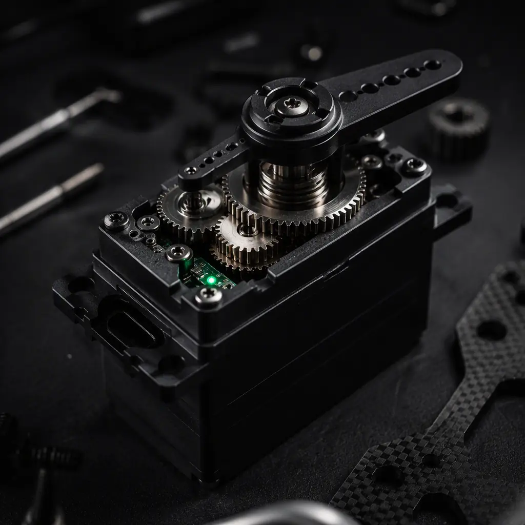
Servo selection sits between two guides already published on this site: the motor KV guide covers the propulsion motor that moves the aircraft through the air, while this guide covers the smaller motors that move the aircraft's control surfaces and mechanisms through their range. The two share sizing logic, torque, thermal limits, gear reduction, but servos add a layer most propulsion motors do not have: position feedback and a command signal from the flight controller. The communication protocols guide covers the signal side in detail; here we focus on the electromechanical side and the numbers that matter when you write the purchase order.
Why servo selection is a flight-safety decision
A control surface that does not move is not a nuisance, it is a failure mode. On a 25 kg fixed-wing UAV flying at 30 m/s, the elevator hinge moment can exceed 4 N·m in a dive, and the servo must hold that load continuously without stalling, stripping teeth or drifting from the commanded position. Undersized servos are one of the most common root causes of control loss in homebuilt and lightly-specified UAVs, because the failure is gradual: the surface moves fine in a bench test, then a hard maneuver loads the hinge past the servo's torque ceiling and the surface blows back. The procurement question is not "what servo fits the servo bay" but "what torque, speed and precision does this surface need, and what margin does the servo hold above it." The rest of this guide answers that question with numbers.
Hinge-moment math: sizing torque before you look at a datasheet
The starting point for any control-surface servo is the hinge moment, the aerodynamic torque the surface generates around its hinge line at the aircraft's maximum speed. The simplified engineering form is:
Hm = q × S × c × C_h
- q = dynamic pressure = 0.5 × ρ × V² (at sea level, ρ ≈ 1.225 kg/m³)
- S = control surface area (m²), measured aft of the hinge line
- c = mean chord of the surface (m)
- C_h = hinge moment coefficient, typically 0.02-0.05 for a plain flap-type surface; use the upper end for high-deflection or large-chord flaps
Worked example: an elevator with S = 0.05 m², c = 0.12 m and C_h = 0.035 at V = 40 m/s gives q = 0.5 × 1.225 × 1600 ≈ 980 Pa, so Hm ≈ 980 × 0.05 × 0.12 × 0.035 ≈ 0.21 N·m ≈ 2.1 kg·cm. That is the bare hinge moment. The servo torque requirement is Hm divided by the mechanical advantage of the linkage (horn radius ÷ servo arm radius) and then multiplied by a factor of safety. The practical convention for UAV control surfaces is 2×-3× to cover gusts, degraded surfaces and control-law overshoot. A 2.1 kg·cm hinge moment with a 1:1 horn ratio and 3× margin becomes a 6.3 kg·cm minimum servo torque. A servo that meets the number with 20% headroom, roughly 8 kg·cm, is a defensible choice; a servo that only meets the bare hinge moment is a test flight waiting to fail. For tilt mechanisms on VTOL aircraft the load is gravitational rather than aerodynamic. The actuator lifts a motor-and-propeller assembly against gravity, so the sizing input is mass × moment arm × dynamic factor (typically 1.5×-2× for in-flight tilt transients). The VTOL transition components guide covers that load case in depth.
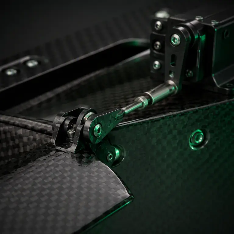 Hinge and linkage
Coreless vs core vs brushless: what the three servo classes deliver
Servo motors come in three construction classes, and the differences are mechanical, not marketing:
| Class | Typical torque range | Strengths | Weaknesses |
|---|---|---|---|
| Core (brushed iron-core) | 1-8 kg·cm | Cheapest, simple, adequate for non-critical surfaces and payload release | Slower response, wider deadband, brushes wear, cogging at low speed |
| Coreless (brushed, ironless) | 2-15 kg·cm | Low rotor inertia, fast response, smooth low-speed control, good value for mid-size surfaces | Brushes still wear; heats faster under continuous stall loads |
| Brushless (BLDC servo) | 5-60+ kg·cm | No brush wear, high continuous torque, long life, best thermal endurance | Most expensive; needs a driver circuit that adds a little current draw at idle |
The class choice follows duty cycle more than peak torque. A payload release mechanism that fires a few times per sortie can use a core servo, the payload release mechanisms guide uses them exactly that way. A tilt actuator or a large elevator that holds load for the entire flight wants coreless at minimum and brushless where the mission is long-endurance or the surface is flight-critical. The lifetime difference is real: a brushed servo's commutator is rated for roughly 10,000-50,000 hours of light use but far fewer under sustained load, while a brushless servo's limiting factor is the bearing, not the motor.
Gear trains: metal vs nylon, and what stripping really means
The gear train converts the motor's high-speed, low-torque output into the servo arm's low-speed, high-torque motion, and it is the first component to fail when torque is undersized. Three material tiers dominate UAV servos:
- Nylon / composite gears. Light, quiet and cheap, they deform before they break, which protects the motor and the surface linkage by acting as a mechanical fuse. They are acceptable for non-critical, low-load surfaces but wear quickly under vibration and grit, and a stripped nylon tooth in flight is still a dead surface.
- Steel gears. The standard for flight-critical surfaces: hard-wearing, predictable backlash, survives repeated stall loads. The weight penalty is small at UAV scale (a full steel train adds roughly 10-20 g on a 40-60 g servo).
- Titanium gears. Specified where a servo must shed every gram and still survive hard landings, common on high-end FPV and VTOL airframes. Cost is the only real objection.
Backlash, the free play between meshed teeth, is the number that matters for precision. A typical metal train has 0.5-1.5° of backlash at the output arm; cheap nylon trains can show 2-3°. On a high-aspect-ratio wing, 1° of elevator backlash at 30 m/s translates into a noticeable pitch wobble that the autopilot then fights. If the surface must hold position precisely (tilt, flaps, camera mechanisms), ask for the backlash spec and treat anything above 1.5° as a warning flag.
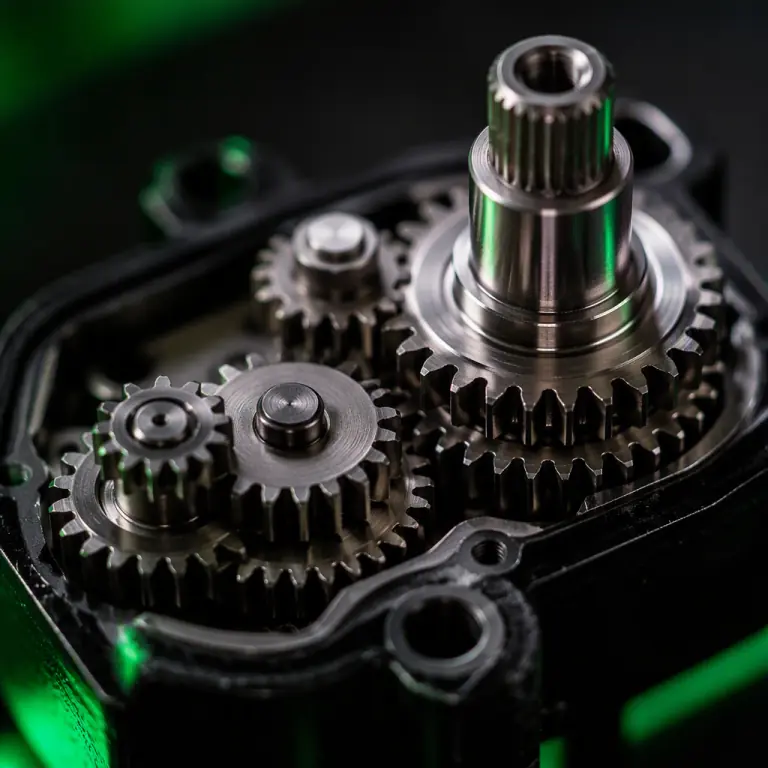 Gear train
Feedback: potentiometer vs magnetic encoder
Every servo is a closed-loop position controller internally. The motor runs until the feedback element reports the commanded position. The feedback element sets the precision ceiling:
- Potentiometer (analog). A resistive track and wiper measure output-arm angle. Cheap and proven, but the wiper wears, the track degrades with vibration, and resolution is limited by electrical noise. Typical usable resolution is 8-10 bits, fine for a rudder, marginal for a gimbal-style mechanism. A worn pot is the classic cause of a servo that "hunts" or drifts over time.
- Magnetic encoder (digital). A magnet on the output shaft and a Hall-effect or magnetoresistive sensor read the angle without contact. No wear, no wiper noise, 12-16 bit resolution in practice, and stable centering over the servo's life. Digital servos with magnetic encoders also support tighter deadband. The deadband is the angular window in which the servo ignores small command errors: 1-2 µs of pulse width on a digital servo vs 5-8 µs on an analog unit. Tight deadband means the surface sits exactly where commanded instead of hovering in a small dead zone, which directly improves autopilot trim and reduces control-surface buzz.
The decision rule: any servo on a flight-critical surface or a precision mechanism (tilt, camera, release) should be digital with a magnetic encoder. Analog potentiometer servos remain acceptable for non-critical surfaces where cost per channel matters, but they should be treated as a maintenance item. Pot wear is a scheduled replacement, not a surprise.
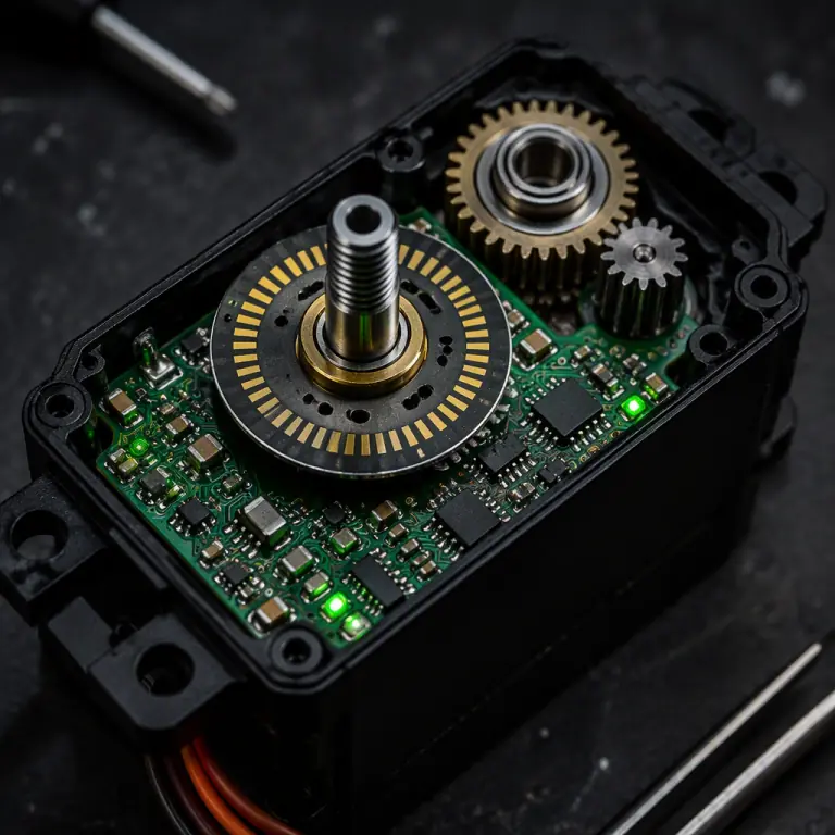 Feedback electronics
Speed, voltage and current: reading the dynamic numbers
Torque is the headline number, but three dynamic specifications decide whether the servo can actually use it:
- Speed. Quoted as seconds per 60° at a reference voltage (typically 0.08-0.15 s/60° for control-surface servos). A fast surface is not automatically better, speed beyond what the control law commands just adds current draw and mechanical wear. The requirement comes from the aircraft's control bandwidth: a 25-35 m/s fixed-wing needs roughly 0.10-0.15 s/60° on elevator and aileron; a slow-flying multirotor's camera tilt can be 0.3 s/60° and still feel responsive.
- Operating voltage. 4.8-6.0 V is the legacy standard; HV servos run 6.0-8.4 V and deliver proportionally more torque and speed. The airframe's servo rail voltage must match. Running an HV servo on a 5 V rail leaves half its torque unused, while feeding a 5 V servo from an 8.4 V rail risks smoke. Specify the rail voltage first (the connectors and wiring guide covers servo rail design), then match servos to it.
- Current draw. A digital servo can draw 0.5-2 A in normal maneuvering and 3-10 A at stall. Three stalled surfaces on one 5 V BEC rated for 5 A means brownout. The classic cause of "the whole aircraft twitched." The servo rail must be sized for the sum of simultaneous worst-case currents, not the idle current, and the flight controller's power supply must be isolated from the servo rail. The payload power budgeting guide covers rail design and sequencing in detail.
Signal compatibility: PWM, SBUS and the flight controller
UAV servos are commanded by the flight controller's servo outputs, and compatibility is a five-minute check that prevents a two-hour integration session:
- PWM. The universal standard: a 1-2 ms pulse repeated at 50 Hz (analog) to 333 Hz (digital). ArduPilot and PX4 both output PWM on their servo channels; a digital servo accepts the full 50-333 Hz range, while an analog servo must not be driven above ~50 Hz or it overheats. This is the single most common servo damage mode in UAV builds, an analog servo on a 333 Hz output rail.
- SBUS and serial bus servos. Some servos accept SBUS or other serial protocols directly, which reduces wiring on multi-surface aircraft. In practice, most UAV flight controllers still drive servos via PWM, and serial-bus servos add a decoder and a failure mode; specify PWM unless the airframe integrator explicitly designs for serial servos. The communication protocols guide compares the signal standards in detail.
- Signal rail isolation. The flight controller's servo outputs should be opto-isolated or powered from the servo rail, not from the autopilot's logic supply. A stalled servo pulling 8 A must not reset the autopilot. This is a wiring decision, covered in the connectors and wiring guide, and it is non-negotiable on flight-critical surfaces.
Redundancy: dual servos, split surfaces and failure behavior
A single servo driving a flight-critical surface is a single point of failure. The standard mitigations, in increasing order of cost and complexity:
- Dual servos on one surface. Two servos drive the same surface through separate horns and a shared linkage or a bushed torque tube. With matched servos and a shared command, the pair shares load; if one jams, the other can still move the surface if the linkage allows (a compliant coupling or slotted horn). This is the common configuration on mid-size VTOL and fixed-wing aircraft, the VTOL transition guide shows it on tilt mechanisms.
- Split surfaces. The elevator or rudder is split into two independently-driven halves, each on its own servo channel. Losing one half leaves the aircraft controllable, at reduced authority, and the autopilot can trim against the asymmetry. This is the configuration on most twin-boom and large fixed-wing UAVs.
- Independent channels. Each redundant servo is on its own flight-controller output and its own power feed, so a shorted servo or a tripped fuse does not take down both halves. ArduPilot and PX4 both support per-surface output groups; the ArduPilot vs PX4 comparison covers how each stack handles servo output assignment and failsafe outputs.
The redundancy discussion belongs in the design phase, not the spare-parts order. Specify the failure behavior you want, "the aircraft can still land with one half of the elevator", and the airframe designer selects the servo count. A procurement manager buying servos without asking which surfaces are flight-critical will buy the wrong count every time.
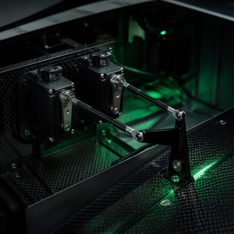 Dual-servo installation
Environmental ratings: temperature, moisture and vibration
A servo is a sealed little gearbox with electronics inside, and the environment decides how long it survives:
- Temperature. Look for an operating range of at least -20°C to +70°C. Below -20°C, standard servo grease stiffens, increasing current draw and slowing response, a real issue for cold-climate operations (the cold-weather components guide covers low-temperature actuation in depth). Above 70°C, brushless servos hold torque far better than brushed units because there is no commutator to soften.
- Moisture and dust. An unsealed servo in a dusty field environment ingests grit through the output shaft seal and dies an early death. For exposed surfaces, landing gear doors, external tilt pods, specify IP54 or better; the IP-rated components guide explains what each rating level actually protects against.
- Vibration. Random vibration from the airframe and propulsion system wears potentiometer tracks and loosens gear meshing. If the servo is mounted near the motor or propeller plane, ask for a vibration-tested unit and check the mount's damping; the propeller balancing and vibration guide covers the airframe-side fix.
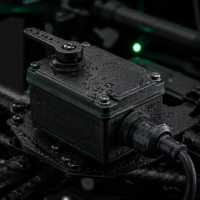 Sealed housing
Servo procurement checklist
- Torque with margin. Compute hinge moment from the aircraft's maximum speed and surface geometry, divide by the linkage mechanical advantage, and multiply by 2×-3×. Never buy to the bare hinge moment.
- Motor class by duty. Coreless or brushless for flight-critical and continuously-loaded surfaces; core servos only for intermittent mechanisms.
- Gears. Steel (or titanium for weight-critical) on flight surfaces, with backlash under 1.5° at the arm.
- Feedback. Digital with magnetic encoder on flight-critical and precision mechanisms; analog pots are a scheduled-maintenance part.
- Speed and voltage. Match s/60° to the control bandwidth, match operating voltage to the servo rail, and size the rail for summed stall currents.
- Signal. Confirm PWM range (50-333 Hz) against the flight controller's output rate; analog servos must never see a digital refresh rate.
- Redundancy. Define which surfaces are flight-critical and specify dual-servo or split-surface configurations with independent channels and feeds.
- Environment. Operating range -20°C to +70°C minimum, IP54+ for exposed surfaces, vibration-tested units near propulsion.
- Test evidence. Demand a bench test log: torque at operating voltage, speed, deadband and current draw measured on the actual units, not the datasheet's best case.
The bottom line: servos are the least glamorous, most safety-critical actuation components in a UAV, and they are sized with arithmetic, not intuition. Compute the hinge moment, apply margin, choose the motor and gear class for the duty cycle, match signal and voltage to the flight controller, and specify redundancy before you need it. EMS Drone supplies matched servo and actuator packages. Torque-specified for your control surfaces, with the gear, feedback, signal and redundancy options your airframe requires. Send your surface geometry and flight speeds, and we will respond with the servo specification, wiring rail design and a bench test plan.
Explore Propulsion Back to Blog
Continue Reading
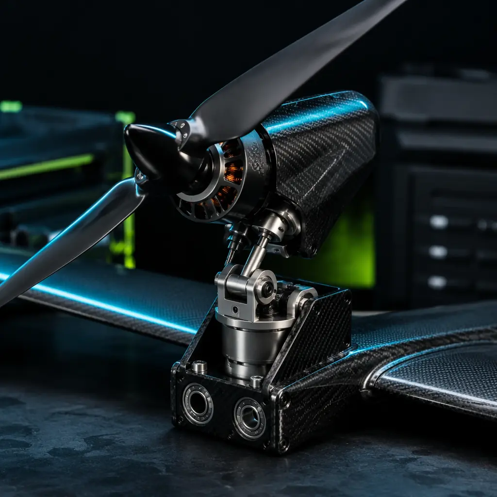
VTOL Transition Components
How tilt actuators are sized and driven on transitioning aircraft.
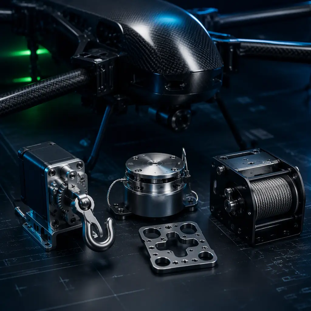
Payload Release Mechanisms
Servo-driven release systems and their actuation trade-offs.
Communication Protocols
PWM, SBUS, CAN and DShot, the signal standards servos speak.
Connectors & Wiring
Servo rail design, connectors and current capacity for multi-servo aircraft.
ArduPilot vs PX4
How each autopilot assigns servo outputs and failsafe behavior.