
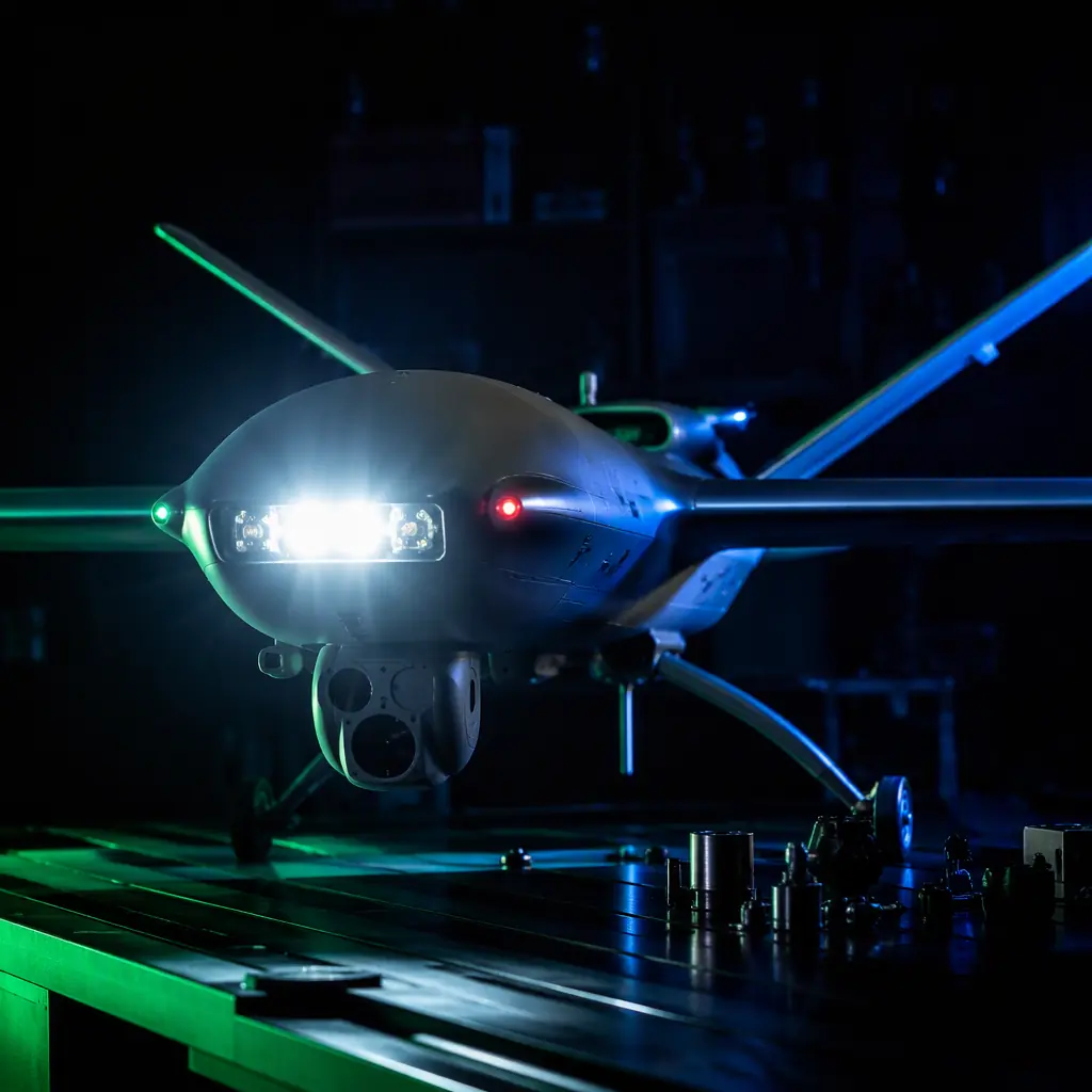
Anti-collision lighting is the visual half of see-and-avoid. Remote ID tells the digital world where the aircraft is; strobes tell the human world where it is. The two are complementary, not interchangeable, which is why a Remote ID and BVLOS compliance program almost always acquires lighting hardware in the same procurement cycle. The requirement lands first, the specifications follow, and the component choice decides whether the aircraft is legal at night or grounded until a replacement part arrives.
The regulatory baseline: what the rules actually require
The rule most UAV programs encounter first is 14 CFR Part 107.29 (US operation at night): a small unmanned aircraft operating at night must have anti-collision lighting visible for at least 3 statute miles (4.8 km). The rule does not specify color, intensity units or flash rate, it specifies a visibility outcome. That is a different requirement from the manned-aircraft rules it borrows from, and the difference matters when a supplier hands you a datasheet with candela numbers.
The manned-aviation benchmark gives the design target. FAR 23.1401 and 25.1401 require anti-collision lights with a minimum effective intensity of 400 candela in the horizontal plane, flashing at 40–100 cycles per minute, in aviation red or white. EASA's national transpositions of the UAS rules vary by state, but the pattern is consistent: night operations require a visible strobe, and the practical European benchmark is a white strobe visible for several kilometers. Military and defense operators add a third requirement, IR strobes visible only through night-vision goggles, so the aircraft can be tracked without revealing its position to the naked eye. The defense and security components guide covers the IR and low-observable side of that requirement in context.
The procurement consequence: before specifying a strobe, the operator must know which rule set applies to the actual operations, FAA Part 107 for US night work, EASA standard scenarios or national rules for Europe, and the customer's military or law-enforcement requirement for defense fleets. The same hardware often satisfies several of these, but the test evidence required differs, which is a supplier-selection question covered in the certification and compliance guide.
 Concept illustration
Strobe specifications: effective intensity, flash rate and color
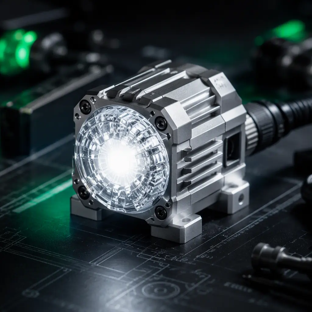
The three numbers on a strobe datasheet that decide compliance are effective intensity, flash rate and chromaticity. Everything else, lumens, power draw, weight, is secondary. Effective intensity is the photometric quantity that visibility rules use: it accounts for the fact that a flashing light appears brighter than its average output, and it is what the 400 candela benchmark refers to. A strobe that claims "2,000 lumens" can still fail the candela requirement if the optics spread the light into the wrong pattern.
| Specification | Typical aviation-grade UAV strobe | Why it matters |
|---|---|---|
| Effective intensity | 100–800 cd (white), ≥400 cd for manned-aircraft benchmark | The number visibility rules are written in |
| Flash rate | 40–100 cycles per minute (manned standard), 20–60 common on UAV units | Flash pattern is what the human eye locks onto |
| Color / chromaticity | Aviation white or aviation red; IR for NVG operations | Legal color is specified, not aesthetic |
| Power draw (average) | 1–6 W at typical duty cycles | Direct impact on the mission power budget |
| Input voltage | 5 V (BEC/USB) to 48 V (direct 12S bus) | Determines the wiring integration path |
| Mass | 10–40 g with housing | Relevant on small platforms |
| Ingress protection | IP65 or better for exposed mounts | Exposed strobes take the full slipstream |
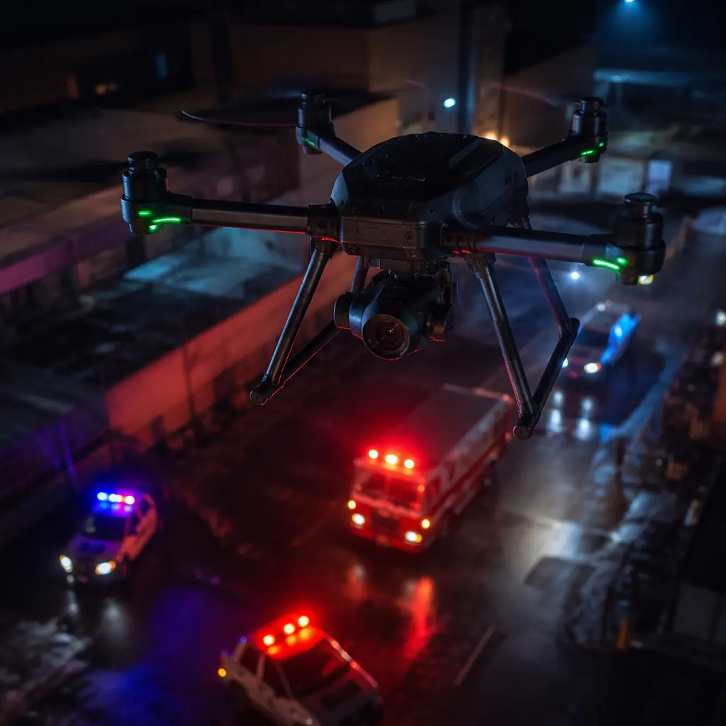
Color is where procurement mistakes happen. Aviation white and aviation red have defined chromaticity boundaries (FAR 23.1397); a generic "red LED" is not necessarily aviation red. If the rule set the operator must satisfy is FAA night ops, white is the safe default and the color question disappears. If the customer operates under military rules, IR mode is usually mandatory and white must be switchable off. The public safety components guide shows how first-responder fleets typically dual-spec white for civilian visibility and IR for tactical phases on the same aircraft.
Power integration: the strobe as a load on the aircraft bus
A strobe is a switching load, and that changes how it must be integrated. The LED driver is a switch-mode converter that takes the aircraft's battery bus (typically 2S–6S, or up to 12S on heavy-lift platforms) and produces a controlled current pulse. The average draw is modest, 1–6 W, but the pulse current at the moment of the flash is several times the average, and the switching frequency can radiate into nearby wiring. Two integration rules follow:
- Feed the strobe from a regulated rail, not the raw bus, when possible. A 5 V or 12 V BEC output keeps the flash brightness consistent as the battery sags under load. On aircraft where the strobe connects directly to the pack, verify the input range covers the full battery swing. A 6S pack at full charge is 25.2 V, at cutoff it is below 19 V, and a strobe rated "6S" may not handle both ends.
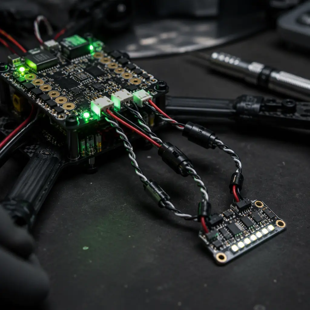
- Keep strobe wiring out of the magnetometer zone and away from unshielded signal runs. The pulse current and the switching frequency are classic EMI sources, and the compass is the most sensitive victim. The connectors, wiring and power distribution guide covers the harness design, twisted pairs, ferrite beads and separation from the IMU/compass cluster, that keeps the strobe from degrading navigation.
The power budget side is small but must be accounted for, not assumed. A six-strobe fleet aircraft at 3 W average per strobe draws 18 W. On a 6S pack that is under 0.8 A, but on a long-endurance platform flying three hours at night, that is roughly 50 Wh of the mission energy. The payload power budgeting guide provides the method for adding lighting loads into the per-phase power draw calculation instead of treating them as negligible.
 Concept illustration
Placement and interference: where the strobe goes changes the aircraft
Placement decides three things: visibility coverage, structural integrity and sensor interference. A strobe buried in the fuselage with the battery underneath it is invisible from half the sky; a strobe on the wingtip of a fixed-wing aircraft is visible in almost every direction but takes the highest vibration and the highest slipstream loads. The practical rules:
- Maximum coverage with minimum parts. One strobe on top of the fuselage covers the upper hemisphere for a multirotor; a fixed wing usually needs one on top and one on the belly for full coverage, or wingtip units. The coverage requirement is angular, not aesthetic. Trace the aircraft silhouette from the directions other traffic can approach.
- Keep the strobe at least 15–20 cm from the GPS/compass module, and test with the strobe flashing. LED drivers with ferrite cores and high pulse currents can bias the magnetometer enough to cause heading drift in flight. The field test is simple: arm the aircraft, flash the strobe, and watch the heading on the ground station. If it shifts more than a degree or two, move the unit or add shielding. The GNSS anti-jamming and spoofing guide covers the broader interference envelope, and the sensor fusion guide explains why a biased compass degrades navigation even when GNSS looks healthy.
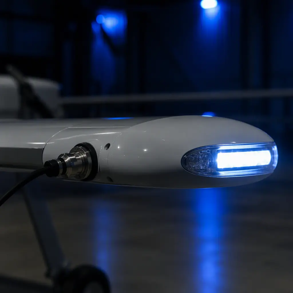
- Mounting must survive vibration and slipstream. Exposed strobes on a multirotor live in the propeller wash; on a fixed wing they live in the full cruise airflow. A 30 g strobe at 30 m/s sees a continuous aerodynamic load plus vibration, the mount must be rated, not just glued. IP65+ housings and locking connectors are the baseline for exposed positions.
 Concept illustration
Beyond the strobe: lighting, Remote ID and detect-and-avoid
Anti-collision lighting sits inside a layered visibility and awareness stack, and the layers are frequently confused in procurement. Remote ID is a digital broadcast that tells nearby receivers who the aircraft is and where it is. It does not help a pilot or a manned aircraft see it. Detect-and-avoid sensors (radar, ADS-B, electro-optical) extend the aircraft's own awareness; they do not make the aircraft visible to others. The strobe is the only layer that works for every human observer in the vicinity, which is why regulators keep it mandatory even for fully autonomous BVLOS concepts. The UTM and detect-and-avoid guide maps where lighting sits in the BVLOS sensor stack, and the FPV and video downlink guide covers the operational side. A night FPV flight is legal only with the lighting, regardless of how good the camera is.
Redundancy is the other procurement question. A single strobe failure at night grounds the aircraft under most rule sets, the operation loses its legal visibility capability. Operators running night programs regularly dual-spec two independent strobes with separate power paths, which is the same philosophy as the redundant architectures in the safety and redundancy systems guide: the failure of one unit degrades, but does not terminate, the operation.
Testing and documentation: evidence the strobe actually complies
The datasheet claim and the compliance evidence are different documents. What a serious buyer should request, and what EMS Drone provides with aviation-grade lighting:
- Photometric test report. Effective intensity (candela) measured on a goniophotometer with the flash pattern defined, not a lumens number from an integrating sphere. This is the evidence the 3-statute-mile or 400 cd claim stands on.
- Flash-rate verification. Cycles per minute measured across the input voltage range. A driver that slows down as the battery sags can drop below the 40 cycles per minute floor.
- Electromagnetic compatibility. Radiated emissions and the conducted noise on the input line, tested against the applicable standard, plus a documented compass-interference test result on a representative airframe.
- Environmental evidence. Temperature range, ingress rating (IP test report), and vibration survival for the intended mounting position.
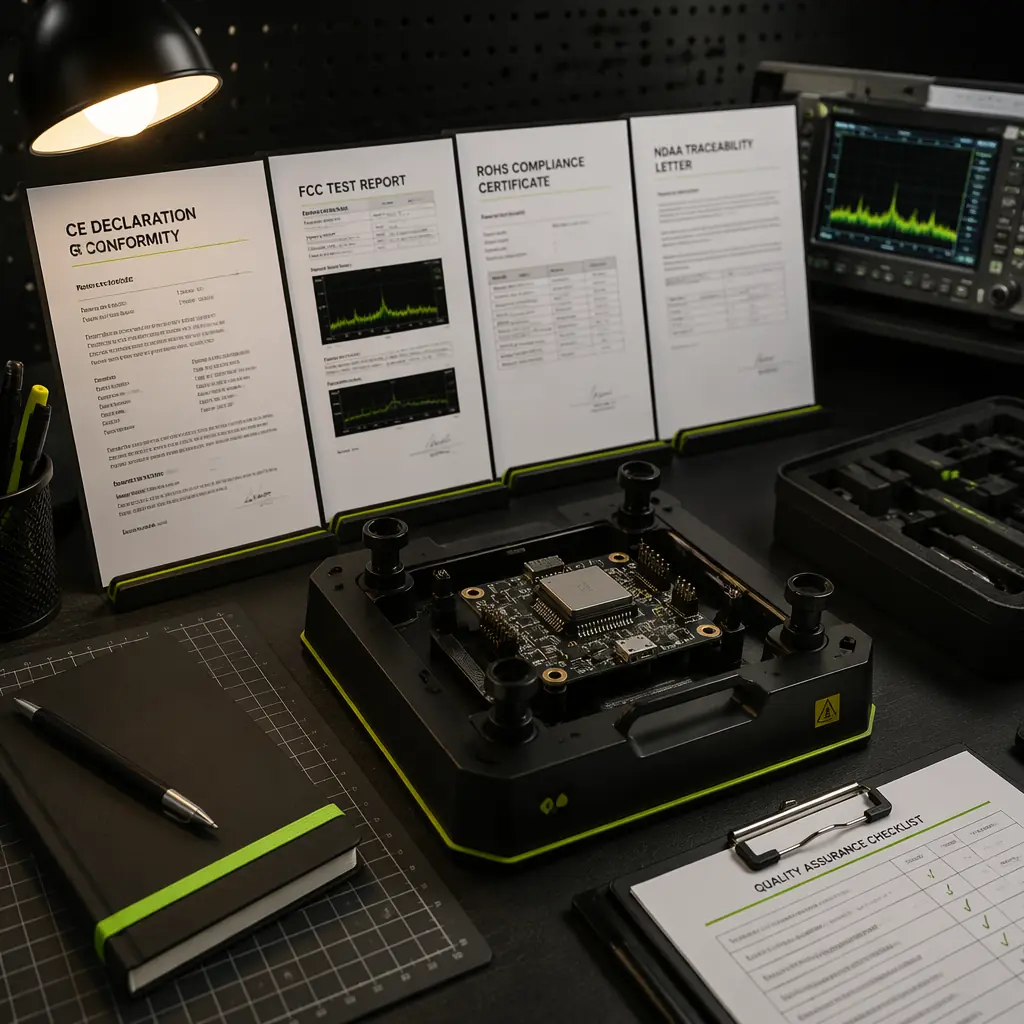
- Import documentation. CE, FCC and RoHS status with the declarations, plus any military-grade restrictions that apply to IR variants, the export side is covered in the export logistics and ITAR/EAR guide.
This evidence set is also the difference between a lighting vendor and a component partner. A strobe that fails photometry in the field is not a warranty swap, it is a grounded fleet. The supplier evaluation checklist frames how to weigh test evidence versus marketing claims in the selection process.
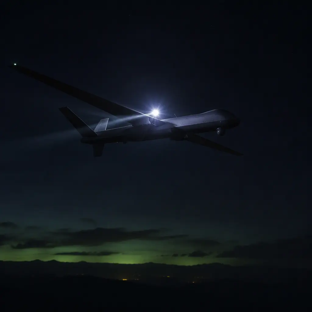 Concept illustration
Procurement checklist: the RFQ clauses that pin lighting to compliance
When the rule set is known, the RFQ should carry six clauses that keep the lighting requirement from evaporating into "any strobe will do":
1. The rule set and the visibility outcome. State the operating regime (FAA Part 107 night, EASA national rule, military IR requirement) and the visibility target in statute miles or kilometers. Verification: the supplier confirms the photometric report against that specific outcome.
2. Effective intensity and flash rate with the measurement method. Minimum candela, cycles per minute, and the photometric standard used. Verification: the goniophotometer report, not the datasheet.
3. Color and modes. Aviation white, aviation red, IR, and the switching behavior between modes (hardware switch, PWM channel, flight-controller command). Verification: chromaticity coordinates for the visible colors and an IR output measurement for the NVG mode.
4. Electrical integration. Input voltage range, average and peak current, connector type, and the EMC test report. Verification: the unit runs from the aircraft's actual rail, this is where a manufacturing quality partner with harness-level integration experience pays for itself.
5. Compass-interference test. A documented test on a representative airframe with the strobe flashing at maximum brightness, showing heading deviation. Verification: the test report with the mounting distance stated.
6. Documentation package. Photometry, EMC, environmental, CE/FCC/RoHS declarations and any export-controlled status. Verification: documents delivered with the first article, not after the fleet is grounded.
The decision, in one line: match the strobe to the rule set first, verify the photometry and the interference test second, and integrate the power path before the airframe is sealed. EMS Drone supplies aviation-grade anti-collision lighting as components or as part of a complete night-operations package. Send the operating regime and the airframe layout, and we will respond with the strobe specification, the photometric evidence, the wiring plan and the integration support for a compliant platform.
Explore custom engineering Back to Blog
EMS Drone manufactures airframe integration under one roof, from component sourcing through production test. If you are specifying for a build, see the full capability set and the tolerances we hold.
Continue Reading
UAV Remote ID and BVLOS Compliance Components
The digital layer of the visibility stack, the broadcast hardware that pairs with visual lighting for night and BVLOS operations.
UTM and Detect-and-Avoid Integration
Where lighting sits inside the BVLOS awareness stack, sensors, traffic data and the human-visibility layer.
UAV Safety and Redundancy Systems
The redundant-architecture philosophy that keeps a strobe failure from grounding a night program.
UAV Component Certification & Compliance
The CE, FCC and RoHS evidence that belongs in every lighting RFQ, and how to verify it.
Public Safety UAV Components
How first-responder fleets dual-spec white and IR lighting for civilian visibility and tactical phases.