
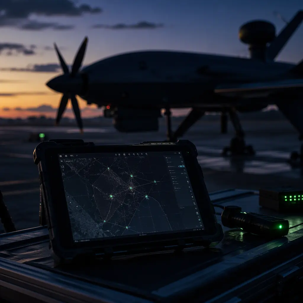
Mission planning sits between the autopilot and the operator, and its importance is easy to underestimate because the software is free. The planning tools that dominate industrial UAV work — Mission Planner, QGroundControl, UgCS and the web-based fleet planners — cost nothing to download, which creates the impression that mission planning is not a procurement decision. It is, for three reasons: the mission file format must match the autopilot stack, the planning workflow must integrate with the team's safety and compliance processes, and the features the planner exposes (terrain data, geofencing, simulation, fail-safe editing) decide how much of the safety engineering actually gets done before the flight. The ArduPilot vs PX4 autopilot comparison covers the flight-controller side of the stack; this article covers the software that tells the autopilot what to do, and pairs with the ground control station hardware guide for the hardware the software runs on.
The mission file: waypoints, actions and the data model
Every mission planner ultimately produces the same artifact: an ordered list of commands the autopilot executes. In ArduPilot and PX4 the mission is a sequence of MAVLink mission items, and the data model is worth understanding because it defines what a mission can and cannot express. Each mission item carries three things: a command (what to do), parameters (the numbers that configure it — coordinates, altitude, speed, and command-specific values), and a frame (whether the values are absolute, relative to home, or relative to terrain).
The command vocabulary. The core set an operator actually uses is small: NAV_WAYPOINT (fly to a position), NAV_LOITER_ variants (circle a point for a time or indefinitely), NAV_TAKEOFF and NAV_LAND (the phase transitions), NAV_SPLINE_WAYPOINT (smooth curved path for gimbal-friendly turns), and the action commands — DO_SET_SERVO, DO_SET_CAM_TRIGG_DIST or DO_SET_CAM_TRIGG_INTERVAL (payload triggers), DO_JUMP (conditional looping), and DO_CHANGE_SPEED. The planning discipline is to know exactly which commands the autopilot stack supports and how it handles an unknown command — a mission with an unsupported item may be rejected at upload, which is a pre-flight failure, or silently skipped, which is worse. The UAV communication protocols guide covers the MAVLink layer that carries these commands and the telemetry that confirms their execution.
Altitude frame and the terrain trap. The frame selection is where planning errors become crashes. Absolute-altitude missions fly at a fixed barometric altitude, which is fine over flat terrain and dangerous over rising ground; relative-to-terrain missions need a terrain database or onboard terrain sensor, and they fail in predictable ways when the data is wrong. The planning rule: for any mission over terrain with more than ~20% relief relative to the planned altitude, the altitude frame decision is a formal review item, not a planner default.
Home and the takeoff sequence. The first mission items define the takeoff and the return behavior: takeoff to a safe altitude, transit to the work area, execute, and end with a return-to-launch or land command. The mission file should never end without an explicit terminal command — an open-ended mission is a fail-safe event waiting for a trigger.
Survey patterns and the coverage math
The most common industrial mission is the area survey, and its planning is pure geometry. The two parameters that define a survey mission are overlap and line spacing, both derived from the payload. For photogrammetry, forward overlap (along the flight line) is typically 70–80% and side overlap (between lines) 60–75%; for LiDAR, the line spacing is set by the scan angle and the required point density rather than image overlap. Line spacing in meters is approximately: (flight altitude × sensor swath fraction) × (1 − side overlap). At 100 m altitude with a 50% swath and 70% side overlap, lines are spaced 15 m apart — which, over a 1 km² area, means roughly 66 lines of 1 km each, or about 66 km of flight line before accounting for turn radius and transit.
Patterns and their turn costs. The planner offers pattern choices that change the economics: parallel boustrophedon (back-and-forth) lines minimize track distance but force a turn at every line end; the turn radius of a fixed-wing or VTOL aircraft at survey speed can be hundreds of meters, which adds unproductive flight time. The UAV VTOL transition components guide covers the airframe side of why fixed-wing surveys and multirotor surveys plan differently — the multirotor turns on a dime but covers area slowly, the fixed-wing covers area fast but needs large turn buffers. The plan output is a coverage time estimate the planner computes from aircraft speed and turn behavior, and the honest number to compare against the battery budget comes from the UAV battery and power management guide — a survey plan that looks efficient on the map and exceeds the pack's usable endurance on the clock is a plan that will fail at the far corner of the area.
Terrain and obstacle integration. The coverage math is two-dimensional; the flight is not. Terrain-following surveys, obstacle avoidance around masts and towers, and the geofence that contains the whole pattern are the three-dimensional layer, covered in the next section. The planning takeaway is that a survey plan is only complete when the area model, the altitude strategy and the geofence are reviewed together — the UAV components for mapping and surveying guide documents the payload and GNSS side of the same equation, where RTK/PPK accuracy converts flight lines into georeferenced products.
 Concept illustration
Geofencing and terrain following: the safety layers
The geofence is the mission's hard boundary — a polygon and altitude band the autopilot will not leave voluntarily. In ArduPilot and PX4 the geofence is enforced in firmware, independent of the operator and the planner: breach the boundary and the autopilot executes the configured action (return to launch, land, or hold). The planning discipline for the geofence:
- The fence is a legal and operational boundary, not a cosmetic one. For operations under remote identification and airspace rules, the geofence is the technical implementation of the airspace authorization — the UAV Remote ID and BVLOS compliance guide covers the regulatory layer that defines where the fence must sit.
- Margin against GPS drift and wind. The fence must sit outside the planned flight lines by a margin that absorbs GNSS position noise and wind-driven excursion — typically 50–150 m for multirotor operations, more for fixed-wing. A fence drawn exactly on the survey boundary will be breached by a routine GPS glitch.
- Altitude ceiling and floor. The vertical fence is as important as the horizontal: a ceiling protects against climb-away failures, a floor (or terrain-following band) protects against descent into terrain. The UAV GNSS module selection guide explains the positioning accuracy that determines how tightly the fence can be drawn.
- Fence behavior in the mission file. The configured breach action (RTL vs land) is a mission-critical decision: RTL assumes the return path is clear and the battery allows it; land assumes the breach point is safe. The choice belongs in the pre-flight review, not in the default settings.
Terrain following adds the ground-distance layer: the aircraft maintains a specified altitude above terrain using a terrain database or a rangefinder. The database approach (SRTM and derived models) has known vertical errors — typically 5–15 m in hilly terrain — and the planning rule is to fly with a terrain-following margin at least three times the database error. The rangefinder approach (downward LiDAR or radar altimeter) is tighter but adds a sensor and its failure mode: a lost rangefinder signal should revert to a safe altitude strategy, and that revert behavior is a planned item, not an autopilot surprise.
Flight modes and fail-safes: what happens when the plan breaks
A mission file is a plan, and every plan eventually meets something it did not anticipate — a lost link, a battery crossing the threshold, a GPS anomaly, a wind shift. The software layer that handles these is the combination of flight modes (the autopilot states the operator or the system can enter) and fail-safes (the automatic transitions when a condition is breached). The planning discipline is to make every fail-safe behavior an explicit review item:
- Return-to-launch parameters. The RTL altitude, the climb behavior before transit, and the loiter-at-home behavior all need values that match the site — an RTL altitude below the local terrain or obstacles is a fail-safe that fails. The UAV safety and redundancy systems guide covers the design-side redundancy that keeps the aircraft capable of executing these behaviors.
- Battery fail-safes. The critical battery level triggers a forced RTL, and the planning question is whether the RTL is reachable: the reserve margin between the fail-safe threshold and the actual landing must cover headwinds, a longer return path, and a go-around. The battery and power management guide provides the endurance math this review uses.
- Link loss behavior. The lost-radio behavior (RTL vs continue-mission vs land) is the highest-stakes decision in the mission file, and it interacts with the UAV RF communication systems guide — the link budget determines how likely the fail-safe is to trigger in the first place.
- Manual override availability. Every automatic behavior must be overridable by the operator with a mode switch, and the override path (which switch, what the transition does mid-maneuver) belongs in the pilot training and the pre-flight brief.
The review artifact is a fail-safe matrix: one row per trigger (link loss, battery critical, geofence breach, GPS loss, motor anomaly), one column per phase of flight (takeoff, transit, work area, return), and the configured behavior in each cell. Operations that maintain this matrix find that the mission planning conversation becomes concrete — every cell is a decision someone has made, rather than a default the software happened to have.
 Concept illustration
Simulation and verification before the first flight
The most valuable feature a mission planning stack offers is the ability to fly the mission before the aircraft does. The two levels of simulation matter differently:
Software-in-the-loop (SITL). The autopilot code runs on the computer, simulating the aircraft model against the mission file. SITL validates the mission logic — command sequence, altitude frames, trigger distances, battery fail-safe timing — without any hardware. It is the correct tool for reviewing a new mission file against a known-good aircraft model, and it costs nothing beyond the setup time.
Hardware-in-the-loop (HIL). The actual flight controller runs the mission with simulated sensors, which validates the hardware-software integration — the firmware version, the parameter set, the sensor configuration — before the aircraft is powered with props. HIL is the correct tool for validating a new aircraft configuration or a firmware change, and the UAV propulsion testing and validation guide covers the bench-test discipline that HIL belongs to: the same verification mindset that catches a reversed motor direction on the bench rather than at takeoff applies to a mission file.
The verification checklist. A mission file passes verification when: the command sequence is fully supported by the firmware, the altitude frames are correct for the terrain, the geofence encloses the entire pattern with margin, the battery fail-safe is reachable under worst-case wind, the payload triggers fire at the intended locations and intervals, and the terminal command returns the aircraft home. That checklist is the difference between a plan and a verified plan — and it is the artifact a professional operation can show a regulator, an insurer or a client when asked what the aircraft is going to do.
The team workflow: plan, review, execute, debrief
Mission planning software is a tool, and like any tool its value depends on the workflow around it. The industrial pattern that works has four steps:
1. Plan. The mission is built from the task brief: the area or target, the payload requirement, the weather and airspace constraints, and the endurance budget. The planner produces the mission file and the coverage/time estimate. This step is where the mapping components and the survey math from this guide converge — the plan is only as good as the area model and the payload numbers fed into it.
2. Review. A second person — not the planner — reviews the mission file against the fail-safe matrix and the site constraints. This is the step that catches the geofence drawn too tight, the RTL altitude below the ridge, the trigger interval that exceeds the payload's duty cycle. For regulated operations the review also checks the plan against the airspace authorization, the Remote ID configuration and the BVLOS limits covered in the Remote ID and BVLOS compliance guide.
3. Execute. The mission file is uploaded, the checklist is run, and the flight proceeds. The execution phase is where the ground station software earns its keep — the ground control station article covers the hardware; the software side is the live map, telemetry and the operator's ability to intervene at any point.
4. Debrief. The flight log, the mission file and the payload data are reviewed together: did the coverage meet the requirement, did the fail-safes behave as configured, did the battery margin hold, and what changes go into the next mission file? The UAV fleet management components guide covers the logging and tracking infrastructure that makes this step data-driven rather than anecdotal — every flight produces the numbers the next plan needs.
The workflow produces a library: every flown mission file becomes a reviewed, verified template for the next similar mission. Organizations that maintain this library find their planning time per mission drops by more than half within a few months, because the review step stops being a re-derivation and becomes a diff against a known-good baseline.
 Concept illustration
The RFQ checklist: 9 line items for the mission software stack
Mission software is specified with the aircraft, not discovered after delivery. The following line items make the software stack a procurement requirement.
1. Autopilot stack compatibility. The flight controller and firmware version the mission software must support, with the MAVLink command set documented. Verification: the compatibility matrix and a test mission file flown in SITL.
2. Mission file portability. The export and import formats for mission files (MAVLink mission protocol, the planner's native format, and any fleet-planning format), so missions are not locked to one vendor's tool. Verification: export and re-import of a sample mission.
3. Terrain data and altitude planning. The terrain source, its resolution and vertical accuracy, and the terrain-following implementation. Verification: a terrain-profile check against a known area.
4. Geofencing. Polygon and altitude fence creation, the breach actions available, and the enforcement location (firmware vs ground software). Verification: a fence breach demonstration in simulation.
5. Fail-safe configuration. The fail-safe triggers and behaviors the planner exposes (link, battery, fence, GPS), and whether they map to the autopilot's firmware fail-safes. Verification: the fail-safe matrix produced for a sample mission.
6. Simulation integration. SITL and HIL support for the mission planning workflow, with the aircraft model fidelity stated. Verification: a mission simulated end to end before flight.
7. Payload integration. Support for the payload's trigger commands (camera interval, gimbal actions, servo or release mechanisms) in the mission editor. Verification: a mission with payload actions executed in simulation.
8. Multi-aircraft and fleet planning. Support for the operation's fleet size — mission upload to multiple aircraft, shared airspace deconfliction, and the swarm communication layer if the operation runs coordinated multi-UAV missions.
9. Training and documentation. Operator training for the planning workflow, the fail-safe matrix process and the debrief loop, with the documentation maintained for the software version delivered. Verification: the training syllabus and the review checklist templates.
The mission software decision completes the operations stack: the autopilot comparison for the flight-control core, the protocols guide for the data layer, and the UTM and detect-and-avoid guide for the airspace layer that mission planning increasingly connects to in BVLOS operations.
Explore custom engineering Back to Blog
Continue Reading

ArduPilot vs PX4: Open-Source Autopilot Comparison
The flight-controller stack the mission file executes on — firmware architecture, command support and the ecosystem around each autopilot.
UAV Ground Control Station Hardware
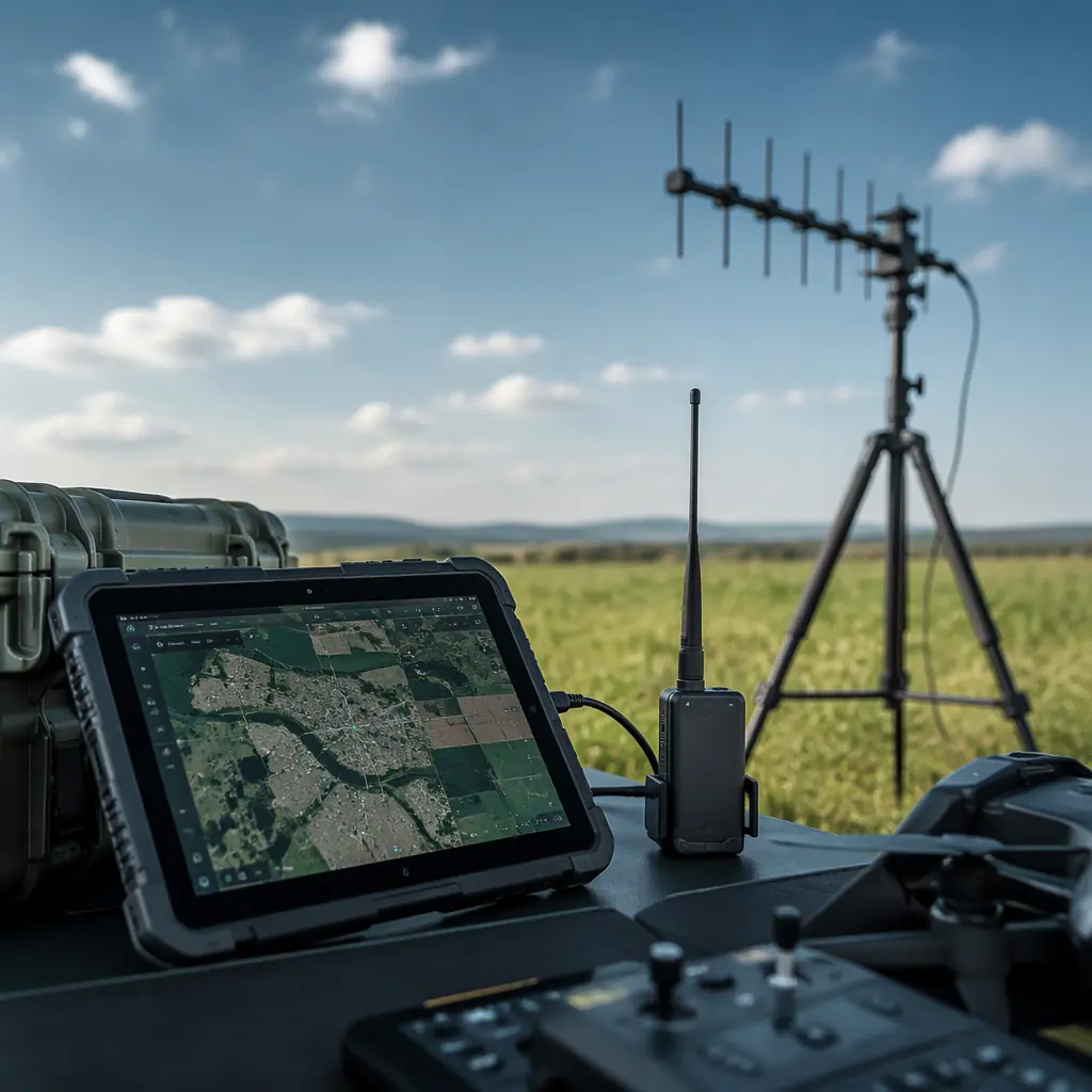
The hardware the planning software runs on — telemetry radios, antennas, computing and the GCS software procurement decision.

UAV Remote ID and BVLOS Compliance
The regulatory layer that defines where the geofence sits and what the mission plan must prove for beyond-visual-line-of-sight operations.
UAV Components for Mapping and Surveying
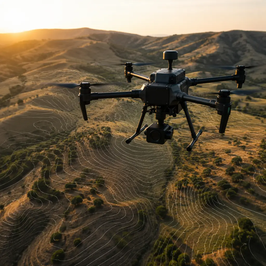
The payload and GNSS side of the coverage equation — the sensors, RTK/PPK and trigger sync that convert flight lines into products.
UTM and Detect-and-Avoid Integration
How mission planning connects to the wider airspace system in BVLOS operations — traffic feeds, contingency routing and DAA sensors.